www.ti.com
2SBAU140A–December 2008–Revised February 2016
Submit Documentation Feedback
Copyright © 2008–2016, Texas Instruments Incorporated
MSOP-8EVM and MSOP-8EVM-PDK
Contents
1 EVM Overview ............................................................................................................... 3
2 Analog Interface.............................................................................................................. 4
3 Digital Interface .............................................................................................................. 4
4 Power Supplies .............................................................................................................. 4
5 EVM Operation............................................................................................................... 7
6 MSOP-8EVM-PDK Kit Operation.......................................................................................... 8
7 Evaluating with the ADCPro Software................................................................................... 18
Appendix A Bill of Materials (BOM) and Schematic......................................................................... 21
List of Figures
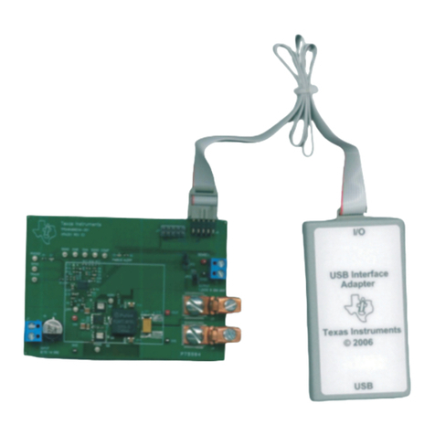
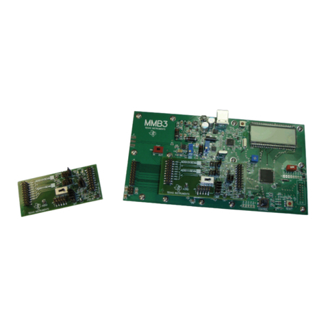
1 MSOP-8EVM (Left) and MSOP-8EVM-PDK (Right) .................................................................... 1
2 MMB0 Initial Setup........................................................................................................... 9
3 MSOP-8 EVM Board Initial Setup........................................................................................ 10
4 Connecting the MSOP-8EVM to the MMB0 Motherboard ............................................................ 10
5 Connecting an AC Adapter ............................................................................................... 11
6 Laboratory Power-Supply Connection................................................................................... 12
7 ADCPro Software Start-up Display Window............................................................................ 13
8 ADS8326EVM-PDK Plug-In Display Window........................................................................... 14
9 Found New Hardware Wizard, Screen 1................................................................................ 15
10 Found New Hardware Wizard, Screen 2................................................................................ 15
11 Found New Hardware Wizard, Screen 3................................................................................ 16
12 Found New Hardware Wizard, Screen 4................................................................................ 16
13 Found New Hardware Wizard, Screen 5................................................................................ 17
14 Continuous Clock—Max SCLK........................................................................................... 18
15 Clockstop Mode—Max SCLK............................................................................................. 19
16 Continuous Mode—Stretched SCLK .................................................................................... 19
17 Progress Bar While Collecting Data ..................................................................................... 20
List of Tables
1 Related Documentation..................................................................................................... 3
2 J1—Analog Interface Pinout................................................................................................ 4
3 J2—Digital Interface Pinout ................................................................................................ 4
4 J3 Pinout...................................................................................................................... 5
5 Jumper Descriptions......................................................................................................... 7
6 Bill of Materials ............................................................................................................. 21
