1
SLAU658–March 2016
Submit Documentation Feedback Copyright © 2016, Texas Instruments Incorporated
PGA411-Q1 EVM User's Guide
MSP430, E2E are trademarks of Texas Instruments.
Windows is a registered trademark of Microsoft Corporation.
All other trademarks are the property of their respective owners.
User's Guide
SLAU658–March 2016
PGA411-Q1 EVM User's Guide
The PGA411-Q1 EVM allows users to evaluate the functionality of the PGA411-Q1 device. This user’s
guide describes both the hardware platform containing a sample PGA411-Q1 device, and the graphical
user interface (GUI) software used to configure the functionality and diagnostics on the PGA411-Q1
resolver-to-digital interface IC. In addition to evaluating the PGA411-Q1 device, the other objective of this
board is to display in the GUI the position (angle) or velocity readings from a resolver sensor.
This document also includes the EVM schematics, bill of materials, and PCB layout.
NOTE: Texas Instruments recommends using the PGA411-Q1 EVM user's guide (this document)
after reading and following the steps listed in the PGA411-Q1 Evaluation Module Quick Start
Guide. To download this guide, go to the product folder: www.ti.com/product/PGA411-Q1.
Contents
1 Introduction ................................................................................................................... 3
2 Setup and Operation ........................................................................................................ 3
2.1 Required Equipment for Device Evaluation ..................................................................... 3
2.2 Initial EVM Setup ................................................................................................... 3
2.3 GUI Software........................................................................................................ 7
3 EVM Evaluation Examples................................................................................................ 16
3.1 EVM Checks for Proper Operation.............................................................................. 16
4 Schematics, Bill of Materials, and Layout............................................................................... 20
4.1 Schematics......................................................................................................... 21
4.2 Bill of Materials .................................................................................................... 23
4.3 Layout and Component Placement............................................................................. 27
List of Figures
1 PGA411-Q1 EVM Block Diagram.......................................................................................... 3
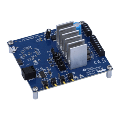
2 PGA411-Q1 EVM............................................................................................................ 4
3 PGA411-Q1 GUI Block Diagram........................................................................................... 5
4 PGA411-Q1 Device Startup Failed........................................................................................ 5
5 GUI PGA41x-Q1 EVM Main Screen ...................................................................................... 8
6 Device-State Status and Selection ........................................................................................ 8
7 Pin Configuration Screen ................................................................................................... 9
8 Memory Map................................................................................................................ 11
9 Bit Selection................................................................................................................. 11
10 Hex Selection (REG)....................................................................................................... 11
11 Search Box and Register Descriptions.................................................................................. 12
12 Data Monitor ................................................................................................................ 13
13 DEMO Screen .............................................................................................................. 14
14 Fault Status ................................................................................................................. 15
15 FAULTRES Change in Block Diagram .................................................................................. 16
16 FAULTRES Change in Pin Configuration Tab ......................................................................... 17
