Table of Contents
Description................................................................................................................................................................................. 1
Features......................................................................................................................................................................................1
1 Evaluation Module Overview................................................................................................................................................. 4
1.1 Introduction........................................................................................................................................................................ 4
1.2 Kit Contents........................................................................................................................................................................4
1.3 Specification.......................................................................................................................................................................4
1.4 Device Information............................................................................................................................................................. 4
2 Hardware................................................................................................................................................................................. 4
2.1 Hardware Features............................................................................................................................................................ 5
2.2 Connector and Jumper Descriptions..................................................................................................................................6
2.3 Power............................................................................................................................................................................... 12
2.4 Clocking........................................................................................................................................................................... 14
2.5 Performing Conducted Testing.........................................................................................................................................15
3 Evaluation Setups.................................................................................................................................................................17
3.1 MCU and RTOS............................................................................................................................................................... 17
3.2 Processor and Linux........................................................................................................................................................ 18
3.3 Standalone RF Testing.....................................................................................................................................................20
4 Radio Tool BP-CC3301 Hardware Setup.............................................................................................................................21
4.1 Option 1: LP-XDS110.......................................................................................................................................................22
4.2 Option 2: XDS110 JTAG Debug Probe............................................................................................................................ 23
4.3 Option 3: SimpleLink Launchpad and 10 pin Cable......................................................................................................... 26
5 Hardware Design Files......................................................................................................................................................... 26
5.1 Schematics.......................................................................................................................................................................26
5.2 PCB Layouts.................................................................................................................................................................... 26
5.3 Bill of Materials (BOM)..................................................................................................................................................... 27
6 Compliance and Certifications............................................................................................................................................ 27
7 Trademarks............................................................................................................................................................................27
List of Figures
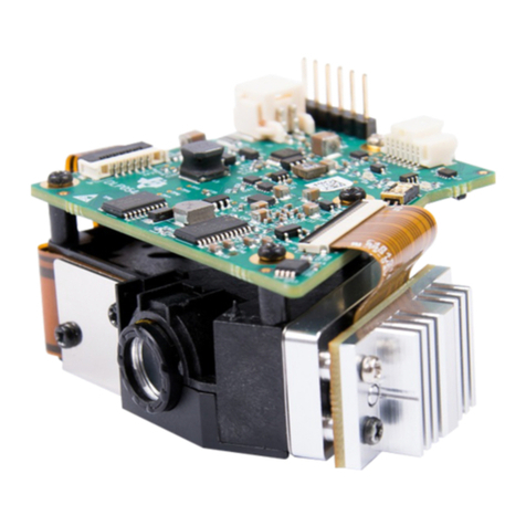
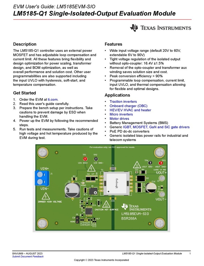
Figure 1-1. BP-CC3301 Front Side..............................................................................................................................................1
Figure 1-1. BP-CC3301 Block Diagram.......................................................................................................................................4
Figure 2-1. BP-CC3301 Overview............................................................................................................................................... 5
Figure 2-2. LEDs D4 & D5........................................................................................................................................................... 6
Figure 2-3. Reset Push-Button.................................................................................................................................................... 6
Figure 2-4. BP-CC3301 BoosterPack Header Pinout..................................................................................................................7
Figure 2-5. ARM 10 pin JTAG Connector (J10)......................................................................................................................... 10
Figure 2-6. 20 pin LP-XDS110 Connector (J11).........................................................................................................................11
Figure 2-7. Low Current Measurement......................................................................................................................................12
Figure 2-8. Active Current Measurement...................................................................................................................................13
Figure 2-9. 40 MHz XTAL (Y1)...................................................................................................................................................14
Figure 2-10. Rework for External Slow Clock Use.....................................................................................................................14
Figure 2-11. RF Path on BP-CC3301........................................................................................................................................ 15
Figure 2-12. U.FL Connector..................................................................................................................................................... 16
Figure 2-13. SMA/U.FL option................................................................................................................................................... 16
Figure 3-1. BP-CC3301 with LP-AM243....................................................................................................................................17
Figure 3-2. BeagleBone Black Board........................................................................................................................................ 18
Figure 3-3. Top View of BP-CC3301 + BBB with Adapter Board...............................................................................................18
Figure 3-4. Side View of BP-CC3301 and BBB with Adapter Board In Between.......................................................................18
Figure 3-5. Adapter Board for the BBB......................................................................................................................................19
Figure 3-6. Top View of Modified BBB....................................................................................................................................... 19
Figure 3-7. Bottom View of Modified BBB..................................................................................................................................20
Figure 4-1. BP-CC3301 Connected to LP-XDS110................................................................................................................... 22
Figure 4-2. XDS110 Debug probe kit.........................................................................................................................................23
Figure 4-3. XDS110 20 pin debug cable with ARM 10 pin Adapter........................................................................................... 23
Figure 4-4. BP-CC3301 ARM 10 pin JTAG connector (J10)......................................................................................................24
Figure 4-5. BP-CC3301 Connected to XDS110.........................................................................................................................25
Figure 4-6. BP-CC3301 Connected to LAUNCHXL-CC3235SF................................................................................................26
List of Tables
Table 2-1. LEDs........................................................................................................................................................................... 6
Table of Contents www.ti.com
2SimpleLink™ CC3301 Wi-Fi 6 and Bluetooth® Low Energy BoosterPack™ Plug-
in Module (BP-CC3301)
SWAU130 – MARCH 2023
Submit Document Feedback
Copyright © 2023 Texas Instruments Incorporated
