System Description
www.ti.com
2TIDUEV8A–December 2019–Revised February 2020
Submit Documentation Feedback
Copyright © 2019–2020, Texas Instruments Incorporated
Integrated Power Supply Reference Design for NXP i.MX 8M Mini Processor
1 System Description
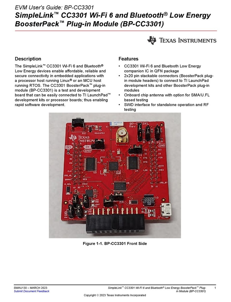
TIDA-050038 is first-and-foremost a reference design for powering the NXP i.MX 8M Mini processor from
the TPS6521825 and LP873347 PMICs. In order to show that the PMICs can power the processor, it
made the most sense to build a SoM board that is compatible with the existing base-board (8MMiniLPD4-
EVK), which includes a variety of peripheral connections to assist with development of various end
equipments. As a result, the base board contains all the large connectors for wired communication, a slot
for an SD Card containing the software image, as well as DIP switches for multiple BOOT options. The
SoM board, on the other hand, contains all the on-board memory and module for wireless communication.
Finally, to ensure the entire board is operational, we developed and tested software using the open-source
embedded Linux Yocto SDK to get started testing this design.
1.1 Key System Specifications
Table 1. Key System Specifications
PARAMETER SPECIFICATIONS DETAILS
Processor i.MX 8M Mini Dual-Core Applications Processor, MIMX8MM6DVTLZAA Section 2.2.1
PMICs
TPS6521825 PMIC for powering RTC (SNVS) domain with GPIOs to enable
external ICs, EEPROM pre-programmed with correct automatic sequencing for
i.MX 8M Mini & DVFS controlled by I2CSection 2.3.1
LP873347PMIC for delivering up to 3 A for core rails of i.MX 8M Mini processor,
OTP pre-programmed with correct sequencing for i.MX 8M Mini & DVFS
controlled by I2CSection 2.3.2
Memory 2GB x32-bit LPDDR4, 512Mb QSPI NOR-Flash (64MB), 8GB eMMC 5.0, SD
v3.0 interface Section 2.2.2
Wifi + Bluetooth Support WiFi + Bluetooth with Murata device. WiFi must support 802.11ac
standard and package size must fit in allotted board area. Section 2.2.3
Current Monitoring 3x TI INA3221 devices are used to monitor current through 9 rails in the system
(all DC-DCs and LDOs providing >100-mA of current) Section 2.3.3
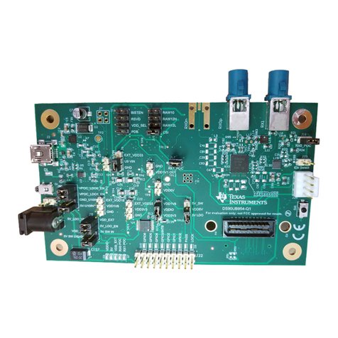
USB2ANY header Debug method for PMIC separate from processor provided by USB2ANY
(standard 100-mil pitch, 10-pin header). Must be outside of 2" x 2" square and
capable of being detached from PCB. Section 2.2.5
Manufacturability The PCB must be completed without HDI (high-density interconnect)
manufacturing technologies. For example, via hole size ≥8 mil and no via-in-
pad allowed. Section 2.4
Compatibility Must be compatible with 8MMiniLPD4-EVK, using same high-density
connectors from SoM board to base-board Section 2.2.4
Size Main PCB (excluding USB2ANY header) must be same size as original
8MMiniLPD4-EVK SoM board, 2" x 2" Section 2.4.1
