2.2 Default Configuration and Connections
2.2.1 USB-MODEVM
2.2.2 TLV320AIC3104 Jumper Locations
EVM Description and Basics
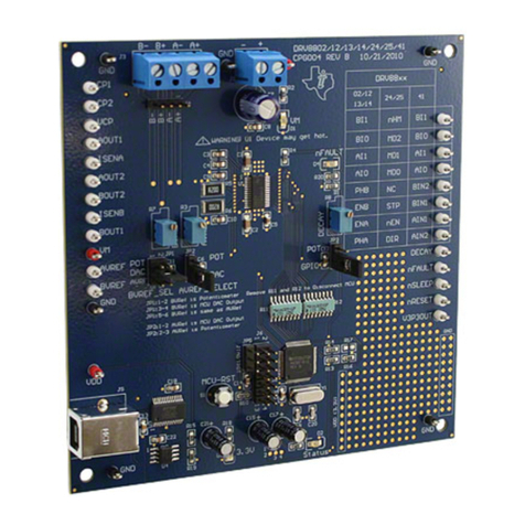
Table 1 provides a list of the SW2 settings on the USB=MODEVM. For use with the TLV320AIC3104EVM,SW-2 positions 1 through 7 should be set to ON, while SW-2.8 should be set to OFF.
Table 1. USB-MODEVM SW2 Settings
SW-2 Switch Number Label Switch Description
1 A0 USB-MODEVM EEPROM I
2
C Address A0ON: A0 = 0OFF: A0 = 12 A1 USB-MODEVM EEPROM I
2
C Address A1ON: A1 = 0OFF: A1 = 13 A2 USB-MODEVM EEPROM I
2
C Address A2ON: A2 = 0OFF: A2 = 14 USB I
2
S I
2
S Bus Source SelectionON: I
2
S Bus connects to TAS1020OFF: I
2
S Bus connects to USB-MODEVM J145 USB MCK I
2
S Bus MCLK Source SelectionON: MCLK connects to TAS1020OFF: MCLK connects to USB-MODEVM J146 USB SPI SPI Bus Source SelectionON: SPI Bus connects to TAS1020OFF: SPI Bus connects to USB-MODEVM J157 USB RST RST Source SelectionON: EVM Reset Signal comes from TAS1020OFF: EVM Reset Signal comes from USB-MODEVM J158 EXT MCK External MCLK SelectionON: MCLK Signal is provided from USB-MODEVM J10OFF: MCLK Signal comes from either selection of SW2-5
Table 2 provides a list of jumpers found on the EVM and their factory default conditions.
Table 2. List of JumpersDefaultJumper Position Jumper Description
JMP1 2-3 When connecting 2-3, mic bias comes from the MICBIAS pin on the device; when connecting 1-2, mic bias is supplied from thepower supply through a resistor, which the user must install.
JMP2 Installed Connects onboard Mic to Left Microphone Input.
JMP3 Installed Connects onboard Mic to Right Microphone Input.
JMP4 Installed Provides a means of measuring IOVDD current.
JMP5 Installed Provides a means of measuring AVDD_ADC current.
JMP6 Installed Provides a means of measuring DVDD current.
JMP7 Installed Provides a means of measuring DRVDD current.
JMP8 Installed Provides a means of measuring AVDD_DAC current.
JMP9 Installed Connects Analog and Digital Grounds.
JMP10 3-5
When connecting 3 to 5, I
2
C is selected as control mode; when connecting 1 to 3, SPI is selected as control mode. Whenconnecting 3 to 4, mode selection can be made by a logic level at J16.12
JMP11 3-5
In I
2
C control mode, this jumper sets the state of A0. When connecting 3 to 5, A0 = 0; when connecting 1 to 3, A0 = 1. In SPI controlmode, connecting 3 to 4, SPI /SS is provided from J16.2
JMP12 3-5
In I
2
C control mode, this jumper sets the state of A1. When connecting 3 to 5, A1 = 0; when connecting 1 to 3, A1 = 1. In SPI controlmode, connecting 3 to 4, SPI SCLK is provided from J16.3
JMP13 Installed When installed, shorts across the output capacitor on HPLOUT; remove this jumper if using AC-coupled output drive
SLAU218 – August 2007 TLV320AIC3104EVM and TLV320AIC3104EVM-PDK 5Submit Documentation Feedback


