User’s Guide
TPS650330-Q1 EVM User's Guide
ABSTRACT
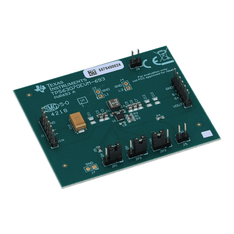
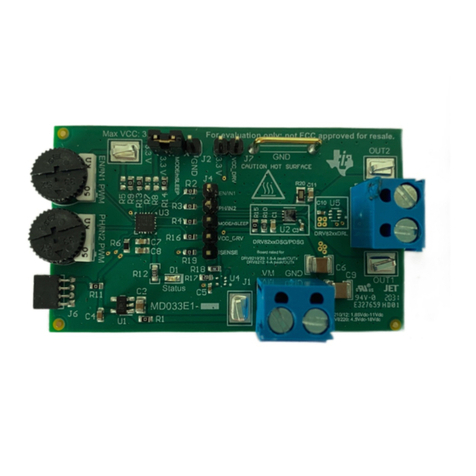
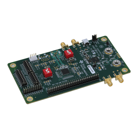
The TPS650330-Q1 EVM is an evaluation board for the TPS65033x-Q1 Power Management Integrated Circuits
(PMICs). The EVM includes an onboard USB-to-I2C adapter, power terminals and jumpers for all DC regulator
inputs and outputs, and test points for common measurements.
Table of Contents
1 Introduction.............................................................................................................................................................................3
2 Requirements..........................................................................................................................................................................3
3 Operation Instructions........................................................................................................................................................... 3
4 EVM Configurations................................................................................................................................................................6
5 Test Points...............................................................................................................................................................................7
6 Graphical User Interface........................................................................................................................................................ 8
7 Typical Performance Plots................................................................................................................................................... 18
8 TPS650330-Q1 EVM Schematic........................................................................................................................................... 21
9 TPS650330-Q1 EVM PCB Layers.........................................................................................................................................23
10 TPS650330-Q1 EVM Bill of Materials................................................................................................................................ 29
11 TPS650330-Q1 Silicon Revision Changes........................................................................................................................ 32
12 Revision History................................................................................................................................................................. 33
List of Figures
Figure 4-1. TPS650330-Q1 EVM Top View................................................................................................................................. 6
Figure 5-1. TPS650330-Q1 EVM Test Point Locations............................................................................................................... 8
Figure 6-1. TPS650330-Q1 EVM Debugging Flow Chart............................................................................................................9
Figure 6-2. Opening Serial Port Options....................................................................................................................................10
Figure 6-3. Selecting an Alternate Port......................................................................................................................................10
Figure 6-4. TPS6503xx-Q1 GUI Home Screen..........................................................................................................................11
Figure 6-5. TPS6503xx-Q1 GUI Block Diagram Page...............................................................................................................12
Figure 6-6. Register Page Interfaces.........................................................................................................................................12
Figure 6-7. TPS6503xx-Q1 GUI Device Configuration Page.....................................................................................................13
Figure 6-8. Device Selection for Generating NVM Settings.......................................................................................................14
Figure 6-9. Example Settings Output.........................................................................................................................................14
Figure 6-10. Sequencing Overview Tab.....................................................................................................................................15
Figure 6-11. Sequencing Overview Including GPIO.................................................................................................................. 15
Figure 6-12. GUI Generated Timing Diagram............................................................................................................................16
Figure 6-13. TPS6503xx-Q1 GUI Re-Program PMIC Page...................................................................................................... 16
Figure 6-14. GUI Configuration CRC Script...............................................................................................................................17
Figure 7-1. TPS650330-Q1 Default Power Up Sequence......................................................................................................... 18
Figure 7-2. TPS650330-Q1 Default Power Down Sequence.................................................................................................... 18
Figure 8-1. TPS650330-Q1 Schematic......................................................................................................................................21
Figure 8-2. MSP432E401Y Schematic...................................................................................................................................... 22
Figure 9-1. Top Layer.................................................................................................................................................................23
Figure 9-2. Mid-Layer 1............................................................................................................................................................. 24
Figure 9-3. Mid-Layer 2............................................................................................................................................................. 25
Figure 9-4. Mid-Layer 3............................................................................................................................................................. 26
Figure 9-5. Mid-Layer 4............................................................................................................................................................. 27
Figure 9-6. Bottom Layer (Mirrored).......................................................................................................................................... 28
List of Tables
Table 3-1. Adapter Power Source (J18).......................................................................................................................................3
Table 3-2. Dedicated LDO Supply for Adapter (J19)................................................................................................................... 3
Table 3-3. Adapter PMIC Connections........................................................................................................................................ 4
www.ti.com Table of Contents
SLVUBI2A – JULY 2018 – REVISED OCTOBER 2020
Submit Document Feedback
TPS650330-Q1 EVM User's Guide 1
Copyright © 2020 Texas Instruments Incorporated
