User’s Guide
TPS6594x-Q1 Evaluation Module
ABSTRACT
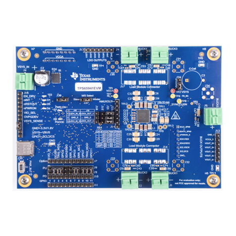
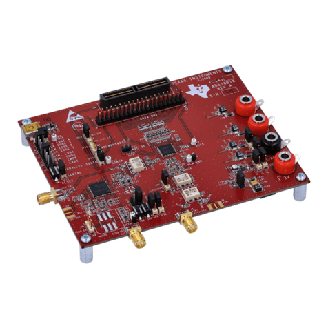
The TPS6594x-Q1 and TPS6593x-Q1 evaluation modules (EVM) highlight the performance and flexibility of the
TPS6594x-Q1 and TPS6593x-Q1 power management ICs (PMICs). The modular design allows the EVMs to be
stacked, which provides a multi-PMIC solution and increases the scalability of these EVMs to develop and
evaluate a wide range of power applications. The scalability of the products supports up to six devices, with one
primary and up to five secondary PMICs. This document enumerates the features and interfaces provided to
develop and evaluate the PMIC.
Warning Warning Hot surface.
Contact may cause burns.
Do not touch!
Table of Contents
1 Introduction.............................................................................................................................................................................3
2 Getting Started........................................................................................................................................................................3
2.1 Getting Started: Single EVM.............................................................................................................................................. 5
2.2 Getting Started: Multiple EVM Evaluation.......................................................................................................................... 5
2.3 The GUI Tool...................................................................................................................................................................... 5
3 EVM Details............................................................................................................................................................................. 5
3.1 Differences Between the TPS6594EVM and the TPS6593EVM........................................................................................6
3.2 Terminal Blocks.................................................................................................................................................................. 6
3.3 Test Point Descriptions.......................................................................................................................................................7
3.4 Configuration Headers....................................................................................................................................................... 7
3.5 Signal Headers...................................................................................................................................................................9
3.6 Stack-Up Headers............................................................................................................................................................10
3.7 Connectors.......................................................................................................................................................................13
3.8 EVM Control, GPIO, and Additional Regulators...............................................................................................................13
4 Customization....................................................................................................................................................................... 13
4.1 Changing the Communication Interface...........................................................................................................................13
4.2 Changing the Phase Configuration.................................................................................................................................. 16
5 Schematic, Layout, and Bill of Materials............................................................................................................................ 17
6 Additional Resources...........................................................................................................................................................37
7 Revision History................................................................................................................................................................... 37
List of Figures
Figure 2-1. TPS6594EVM Top View............................................................................................................................................ 4
Figure 2-2. TPS6593EVM Top View............................................................................................................................................ 4
Figure 3-1. TPS6594EVM Header J7.......................................................................................................................................... 7
Figure 3-2. TPS6593EVM Header J7.......................................................................................................................................... 8
Figure 3-3. LDO_Headers_v2....................................................................................................................................................10
Figure 3-4. EVM Masters Slave Configuration...........................................................................................................................11
Figure 3-5. EVM Bottom View Version 2....................................................................................................................................11
Figure 3-6. Header J37 Master and Slave Select Table Description for 'OPEN' configuration..................................................12
Figure 4-1. TPS6594EVM Interface Settings for Communication............................................................................................. 14
Figure 4-2. TPS6593EVM Interface Settings for Communication............................................................................................. 15
Figure 4-3. Phase Configuration Components.......................................................................................................................... 16
Figure 5-1. TPS6594EVM 1+1+1+1+1 Configuration, Schematic Page 1.................................................................................17
Figure 5-2. TPS6594EVM 1+1+1+1+1 Configuration, Schematic Page 2.................................................................................18
Figure 5-3. TPS6593EVM 1+1+1+1+1 Configuration, Schematic Page 1.................................................................................19
www.ti.com Table of Contents
SLVUBT0A – JUNE 2020 – REVISED JANUARY 2021
Submit Document Feedback
TPS6594x-Q1 Evaluation Module 1
Copyright © 2021 Texas Instruments Incorporated
