1
SLVUBT0–December 2019
Submit Documentation Feedback Copyright © 2019, Texas Instruments Incorporated
TPS6594x-Q1 Evaluation Module
User's Guide
SLVUBT0–December 2019
TPS6594x-Q1 Evaluation Module
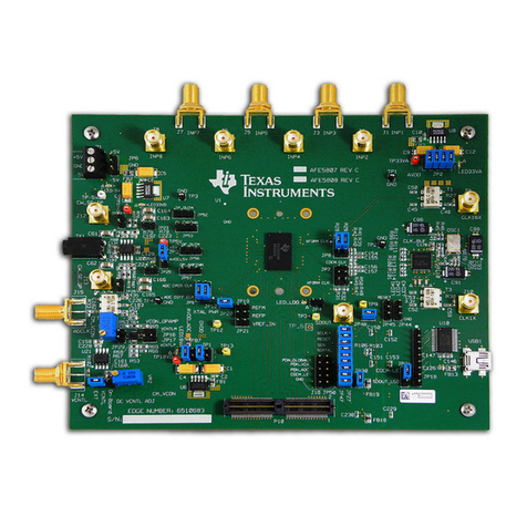
The TPS6594x-Q1 Evaluation Module (EVM) highlights the performance and flexibility of the TPS6594x-
Q1 power management integrated circuit (PMIC). The modular design allows the EVMs to be stacked to
provide a multi-PMIC solution with a single PMIC acting as the master and up to five PMIC slaves. This
document should be used in conjunction with the Programmable Processor PMIC's GUI User's Guide
SLVUBT8 and the TPS6594x-Q1 Power Management IC (PMIC) with 4-phase 14-A Buck for Processors
SLVSEA7.
Contents
1 Introduction ................................................................................................................... 3
2 Getting Started............................................................................................................... 3
2.1 Getting Started: Single EVM ...................................................................................... 3
2.2 Getting Started: Multiple EVM Evaluation ....................................................................... 4
2.3 The GUI Tool........................................................................................................ 4
3 EVM Details .................................................................................................................. 5
3.1 Terminal Blocks..................................................................................................... 5
3.2 Test Point Descriptions ............................................................................................ 5
3.3 Configuration Headers ............................................................................................. 6
3.4 Signal Headers...................................................................................................... 8
3.5 Stack-up Headers................................................................................................... 9
3.6 Connectors......................................................................................................... 12
3.7 EVM Control, GPIO, and additional regulators................................................................ 12
4 Customization............................................................................................................... 12
4.1 Changing the Communication Interface........................................................................ 12
4.2 Changing the Phase Configuration ............................................................................. 14
5 Additional Resources ...................................................................................................... 15
6 Schematic, Layout, and Bill of Materials ................................................................................ 16
7 Typical Data................................................................................................................. 27
8 EMI Data .................................................................................................................... 27
9 Thermal Data ............................................................................................................... 27
List of Figures
1 EVM Top View ............................................................................................................... 4
2 EVM Header J7.............................................................................................................. 6
3 LDO Headers................................................................................................................. 8
4 EVM Masters Slave Configuration......................................................................................... 9
5 EVM Bottom View.......................................................................................................... 10
6 Header J37, Recommended Power Sequence (Enable) for Master and One or More Slaves .................. 11
7 Interface Settings for I2C Communication............................................................................... 13
8 Interface Settings for SPI Communication.............................................................................. 14
9 Phase Configuration Components ....................................................................................... 15
10 Schematic Page 1.......................................................................................................... 16
11 Schematic Page 2.......................................................................................................... 17
12 Layout Top, Layer 1........................................................................................................ 18
13 Layout Ground, Layer 2 .................................................................................................. 19
14 Layout Signal, Layer 3..................................................................................................... 20
