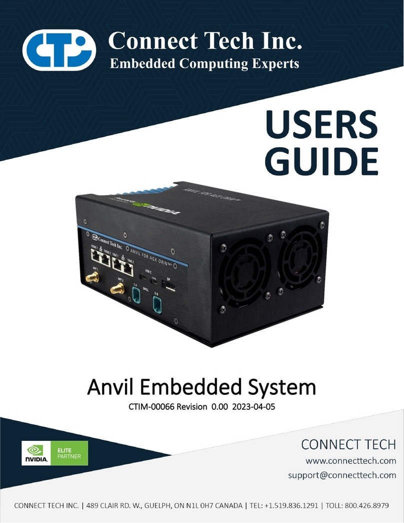
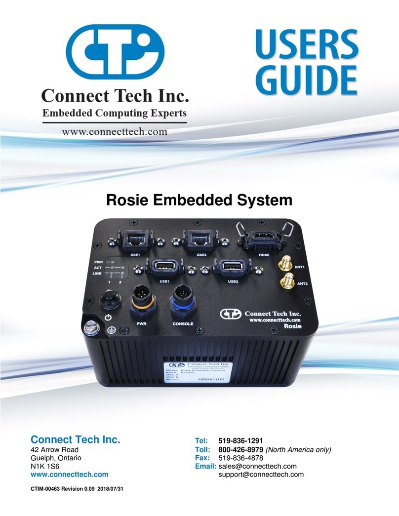
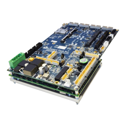
Connect Tech Polaris ESG604 Series User manual

CTI Polaris Users Guide
CTIM-00089 Revision 0.00 2023-07-21

CTI Polaris Users Guide
Users Guide
www.connecttech.com
Document: CTIM-00089
Revision: 0.00
Page 2 of 22
Date: 2023-07-21
TABLE OF CONTENTS
Table of Contents.........................................................................................................................................2
Preface..........................................................................................................................................................4
Disclaimer .......................................................................................................................................................4
Customer Support Overview...........................................................................................................................4
Contact Information ........................................................................................................................................4
Limited Product Warranty...............................................................................................................................5
Copyright Notice.............................................................................................................................................5
Trademark Acknowledgment..........................................................................................................................5
ESD Warning ..................................................................................................................................................6
Revision History...........................................................................................................................................6
Introduction.................................................................................................................................................7
Product Features and Specifications................................................................................................................7
Part Numbers / Ordering Information .............................................................................................................8
Product Overview........................................................................................................................................9
Block Diagram ................................................................................................................................................9
Top View.........................................................................................................................................................9
Front View ....................................................................................................................................................10
Iso View ........................................................................................................................................................10
Back View.....................................................................................................................................................10
Internal Connector Summary & Locations....................................................................................................11
Jumper and Switch Summary & Locations...................................................................................................11
External Connector Summary & Locations...................................................................................................12
Detailed Feature Description.....................................................................................................................13
NVIDIA® Jetson Orin™Board-to-Board Module Connector .....................................................................13
Power Connector...........................................................................................................................................13
GPIO Connector............................................................................................................................................14
CAN Connector.............................................................................................................................................14
Main GbE Connectors...................................................................................................................................15
FAKRA GMSL Connectors..........................................................................................................................16
FAKRA RF Connectors ................................................................................................................................16
USB 3.1 Type-A Connector..........................................................................................................................17
USB microAB Connectors............................................................................................................................17
HDMI Connector...........................................................................................................................................17
Nano-SIM Card Slot......................................................................................................................................18
Main Power Button .......................................................................................................................................18
Reset and Force Recovery Button.................................................................................................................18
Rotary Switch Button....................................................................................................................................19
RGB Status LED...........................................................................................................................................19
Typical Installation....................................................................................................................................20
Mechanical Details..................................................................................................................................... 20
Accessing User Access Panel........................................................................................................................20
Mounting Details...........................................................................................................................................20
Mechanical Drawings & Models................................................................................................................ 20

CTI Polaris Users Guide
Users Guide
www.connecttech.com
Document: CTIM-00089
Revision: 0.00
Page 3 of 22
Date: 2023-07-21
Thermal Details.......................................................................................................................................... 21
RMS POWER Consumption ..................................................................................................................... 21
Software..................................................................................................................................................... 22
Force Recovery Mode................................................................................................................................ 22
Cables.........................................................................................................................................................22
Approved Vendors Cameras ..................................................................................................................... 22

CTI Polaris Users Guide
Users Guide
www.connecttech.com
Document: CTIM-00089
Revision: 0.00
Page 4 of 22
Date: 2023-07-21
PREFACE
Disclaimer
The information contained within this user’s guide, including but not limited to any product specification,
is subject to change without notice.
Connect Tech assumes no liability for any damages incurred directly or indirectly from any technical or
typographical errors or omissions contained herein or for discrepancies between the product and the
user’s guide.
Customer Support Overview
If you experience difficulties after reading the manual and/or using the product, contact the Connect Tech
reseller from which you purchased the product. In most cases the reseller can help you with product
installation and difficulties.
In the event that the reseller is unable to resolve your problem, our highly qualified support staff can assist
you. Support resources are available 24 hours a day, 7 days a week on our website at:
https://connecttech.com/support/resource-center/. See the contact information section below for more
information on how to contact us directly. Our technical support is always free.
Contact Information
Contact Information
Mail/Courier
Connect Tech Inc.
Technical Support
489 Clair Rd. W.
Guelph, Ontario
Canada N1L 0H7
Contact Information
www.connecttech.com
Toll Free: 800-426-8979 (North America only)
Telephone: +1-519-836-1291
Facsimile: 519-836-4878 (on-line 24 hours)
Support
Please go to the Connect Tech Resource Center for product manuals,
installation guides, device drivers, BSPs and technical tips.
Submit your technical support questions to our support engineers.
Technical Support representatives are available Monday through Friday, from
8:30 a.m. to 5:00 p.m. Eastern Standard Time.

CTI Polaris Users Guide
Users Guide
www.connecttech.com
Document: CTIM-00089
Revision: 0.00
Page 5 of 22
Date: 2023-07-21
Limited Product Warranty
Connect Tech Inc. provides a one-year Warranty for this product. Should this product, in Connect Tech
Inc.'s opinion, fail to be in good working order during the warranty period, Connect Tech Inc. will, at its
option, repair or replace this product at no charge, provided that the product has not been subjected to
abuse, misuse, accident, disaster or non-Connect Tech Inc. authorized modification or repair.
You may obtain warranty service by delivering this product to an authorized Connect Tech Inc. business
partner or to Connect Tech Inc. along with proof of purchase. Product returned to Connect Tech Inc. must
be pre-authorized by Connect Tech Inc. with an RMA (Return Material Authorization) number marked on
the outside of the package and sent prepaid, insured and packaged for safe shipment. Connect Tech Inc.
will return this product by prepaid ground shipment service.
The Connect Tech Inc. Limited Warranty is only valid over the serviceable life of the product. This is defined
as the period during which all components are available. Should the product prove to be irreparable,
Connect Tech Inc. reserves the right to substitute an equivalent product if available or to retract the
Warranty if no replacement is available.
The above warranty is the only warranty authorized by Connect Tech Inc. Under no circumstances will
Connect Tech Inc. be liable in any way for any damages, including any lost profits, lost savings or other
incidental or consequential damages arising out of the use of, or inability to use, such product.
Copyright Notice
The information contained in this document is subject to change without notice. Connect Tech Inc. shall
not be liable for errors contained herein or for incidental consequential damages in connection with the
furnishing, performance, or use of this material. This document contains proprietary information that is
protected by copyright. All rights are reserved. No part of this document may be photocopied,
reproduced, or translated to another language without the prior written consent of Connect Tech, Inc.
Copyright
©
2023 by Connect Tech, Inc.
Trademark Acknowledgment
Connect Tech, Inc. acknowledges all trademarks, registered trademarks and/or copyrights referred to in
this document as the property of their respective owners. Not listing all possible trademarks or copyright
acknowledgments does not constitute a lack of acknowledgment to the rightful owners of the trademarks
and copyrights mentioned in this document.

CTI Polaris Users Guide
Users Guide
www.connecttech.com
Document: CTIM-00089
Revision: 0.00
Page 6 of 22
Date: 2023-07-21
ESD Warning
Electronic components and circuits are sensitive to
ElectroStatic Discharge (ESD). When handling any
circuit board assemblies including Connect Tech
COM Express carrier assemblies, it is recommended
that ESD safety precautions be observed. ESD safe
best practices include, but are not limited to:
•Leaving circuit boards in their antistatic packaging
until they are ready to be installed.
•Using a grounded wrist strap when handling
circuit boards, at a minimum you should touch a
grounded metal object to dissipate any static
charge that may be present on you.
•Only handling circuit boards in ESD safe areas,
which may include ESD floor and table mats, wrist
strap stations and ESD safe lab coats.
•Avoiding handling circuit boards in carpeted
areas.
•Try to handle the board by the edges, avoiding
contact with components.
REVISION HISTORY
Revision
Date
Changes
0.00
2023-07-21
Created

CTI Polaris Users Guide
Users Guide
www.connecttech.com
Document: CTIM-00089
Revision: 0.00
Page 7 of 22
Date: 2023-07-21
INTRODUCTION
Connect Tech’s Polarisbrings a deployable NVIDIA® Jetson OrinTM NX and OrinTM Nano to the market.
The Polaris features IP67 enclosure with USB ports, dual-fan, FAKRA SMB plugs, M12 ports, an RGB
status LED, a power button, and non-IP67 ports under IP67 sealed user panel. Polaris is also equipped
with user expansion M.2 (B-Key 3042/3052, M-Key 2280, and E-Key 2230).
Product Features and Specifications
Specifications
NVIDIA® GPU SoC Module
Compatibility
NVIDIA® Jetson OrinTM NX
NVIDIA® Jetson OrinTM Nano
Networking
2x Gigabit Ethernet (M12 X-Code)
1x Gigabit Ethernet (RJ45)
- All ports are from KSZ9897 unmanaged switch
Wireless Expansion
1x WiFi Module (M.2 2230 E-KEY)
1x 5G Module (M.2 3042/3052 B-KEY) w/ nano SIM Card Slot
5x FAKRA SMB Plug C/D/I-codes for antenna connections
Display Output
1x HDMI 1.4b (Type A)
Camera Input
4x FAKRA SMB Plug Z-code, GMSL cameras
USB
3x USB 3.1 (Type A)
1x USB 2.0 OTG (micro AB connector)
UART
1x USB based Debug UART (USB micro AB connector)
Storage
1x M.2 Key-M (NVMe) slot (4-lane PCIe Gen 3/4)
CAN Bus
2x CAN FD Isolated Ports (M12 A-Code)
GPIO
ISOLATED GPIO ports (M12 D-Code):
- 2x 3.3V input (12V tolerant)
- 1x 12V output (100mA max)
Fan (active cooling variant)
2x 12V BLDC Fans with Tachometer and PWM speed control
Other
1x CR2032 RTC battery holder
1x RGB status LED
1x Back-up power button
1x Reset/Forced-Recovery button
1x CAN mode/self-test rotary switch
Input Power
+18-48V DC Wide Input Power (M12 B-Code)
Dimensions
285mm x 150mm x 70mm (11.22inch x 5.91inch x 2.76inch)
Operating Temperature
-20°C to +50°C (-4°F to +122°F)
(14.4CFM is need to operate higher than 35°C or 95°F)

CTI Polaris Users Guide
Users Guide
www.connecttech.com
Document: CTIM-00089
Revision: 0.00
Page 8 of 22
Date: 2023-07-21
Part Numbers / Ordering Information
POLARIS VARIANTS
Base Part Number
Description
ESG604*
Polaris actively cooled version with embedded fans
ESG608*
Polaris passively cooled version that requires user supplied external airflow
PART NUMBERS
ORDERING
PART NUMBER
COOLING
WiFi6
5G
STORAGE
ESG604-1E
ACTIVE
Y
N
2TB
ESG604-22
ACTIVE
N
Y
2TB
ESG604-24
ACTIVE
Y
Y
2TB
ESG604-1C
ACTIVE
N
N
2TB
ESG608-1E
PASSIVE
Y
N
2TB
ESG608-22
PASSIVE
N
Y
2TB
ESG608-24
PASSIVE
Y
Y
2TB
ESG608-1C
PASSIVE
N
N
2TB
*Note that additional configuration possibilities exist with respect to storage and wireless connectivity.
Contact sales@connecttech.com to discuss all available options.

CTI Polaris Users Guide
Users Guide
www.connecttech.com
Document: CTIM-00089
Revision: 0.00
Page 11 of 22
Date: 2023-07-21
Internal Connector Summary & Locations
Designator
Description
P1
HDMI display output connector
P2
Jetson OrinTM NX/Nano module connector
P3
M.2 key-B connector
P4
M.2 key-E connector
P5, P7, P13, P19
MMCX jack GMSL connector
P6, P8
GbE ethernet connectors
P9
CAN connectors
P10
M.2 key-M connector
P11, P21
12V fan connector
P12
Main power connector
P14
Nano SIM card slot
P15
USB2.0 OTG port
P16
USB2.0 debug UART port
P17, P18
USB3.1 dual connector
P20
GPIO connector
P22
On/off button connector
P23
BMS programming connector
P24
GbE RJ45 ethernet connector
Jumper and Switch Summary & Locations
Designator
Description
SW4
Reset and Forced-Recovery mode momentary button
RSW1
CAN Bus Termination control rotary switch

CTI Polaris Users Guide
Users Guide
www.connecttech.com
Document: CTIM-00089
Revision: 0.00
Page 12 of 22
Date: 2023-07-21
External Connector Summary & Locations
Location
Connector
Description
Front
GMSL-1
GMSL-2
GMSL-3
GMSL-4
GMSL FAKRA SMB plug connectors
Front
GbE-1
GbE-2
GbE ethernet –M12 X-code connectors
Front
CAN
CAN –M12 A-code connector
Front
POWER
Power input –M12 B-code connector
Front
USB-1
USB-2
USB3.1 dual port
Front
GPIO
GPIO –M12 D-code connector
Side
RF-1
RF-2
RF-3
RF-4
RF-5
WiFi, LTE, and GNSS antenna connectors
Back
Power Button
Main on/off power button
Back
Status LED
RGB LED
Back
Access Panel
User access panel consisting:
- RESET and Forced-Recovery mode push button
- CAN mode rotary switch
- USB 3.1 Type-A port
- GbE RJ45 port
- HDMI
- USB microAB OTG port
- USB microAB debug UART port
- Nano SIM card slot

CTI Polaris Users Guide
Users Guide
www.connecttech.com
Document: CTIM-00089
Revision: 0.00
Page 13 of 22
Date: 2023-07-21
DETAILED FEATURE DESCRIPTION
NVIDIA® Jetson Orin™Board-to-Board Module Connector
The NVIDIA® OrinTM SoC and NVIDIA® Ampere GPU are implemented on the Jetson OrinTM NX or Nano
system-on-module (SOM). This module is connected to the Polaris’ carrier PCB via a TE Connectivity DDR4
SODIMM 260 Pin connector.
Function
NVIDIA® Jetson Orin™NX/Nano Module
Interface
Location
Internal to Polaris
Type
SOM
Pinout
Refer to NVIDIA® Jetson Orin™System-
on-Module datasheet and OEM design
guide for pinout details
Features
Refer to NVIDIA® Jetson Orin™System-
on-Module datasheet and OEM design
guide for features details
Power Connector
Function
Description
Location
Front
Type
M12 B-Code 5-pin
Part
Number
Amphenol MSBS-05PFFR-SF7003
Mating
Connector
Standard M12 B-Code 5-pin plug.
Example: M12B05ML-12BML
Voltage
+18 –48VDC
Power
Max 185W
Pinout:
Pin
Signal
1
VIN (+)
2
VIN (+)
3
VIN (-)
4
VIN (-)
5
VIN (-)
Outer Shell
Frame Ground

CTI Polaris Users Guide
Users Guide
www.connecttech.com
Document: CTIM-00089
Revision: 0.00
Page 14 of 22
Date: 2023-07-21
GPIO Connector
Function
Description
Location
Front
Type
M12 D-Code 4-pin
Part
Number
Amphenol MSDS-04PFFR-SF7003
Mating
Connector
Standard M12 D-Code 4-pin plug.
Example: TAD14147101-002 (TE)
Voltage
Max I/O 12VDC
Pinout:
Pin
Signal
1
Input1; 2.74k PU to 12V
2
Input2; 2.74k PU to 12V
3
Output1; 12V/100mA
4
VIN (-)
Outer Shell
Frame Ground
CAN Connector
Function
Description
Location
Front
Type
M12 A-Code 8-pin
Part
Number
Amphenol MSAS-08PFFR-SF7003
Mating
Connector
Standard M12 A-Code 8-pin plug.
Example: 1406094 (Phoenix Contact)
Voltage
Max 12VDC, isolated up to 1500VRMS

CTI Polaris Users Guide
Users Guide
www.connecttech.com
Document: CTIM-00089
Revision: 0.00
Page 15 of 22
Date: 2023-07-21
Pinout:
Pin
Signal
1
12V; Max 750mA
2
VIN (-)
3
CAN1H
4
CAN1L
5
GNDCAN1
6
CAN2H
7
CAN2L
8
GNDCAN2
Outer Shell
Frame Ground
Main GbE Connectors
Function
Description
Location
Front
Type
M12 X-Code 8-pin
Part
Number
Amphenol MSXS-08PFFR-SF7003
Mating
Connector
Standard M12 X-Code 8-pin plug
Example: TRG610-T6T-1M
Voltage
Follow IEEE 802.3 standard up to
1000BASE-T, isolated up to 1500VRMS
Pinout:
Pin
Signal
1
ETH –A+
2
ETH –A-
3
ETH –B+
4
ETH –B-
5
ETH –D+
6
ETH –D-
7
ETH –C-
8
ETH –C+
Outer Shell
Frame Ground

CTI Polaris Users Guide
Users Guide
www.connecttech.com
Document: CTIM-00089
Revision: 0.00
Page 16 of 22
Date: 2023-07-21
FAKRA GMSL Connectors
Function
Description
Location
Front
Type
FAKRA SMB Plug Z-Code (water blue)
Part
Number
SHM. 900. 0006-72.Z.I.A-XX
Mating
Connector
Standard FAKRA Jack Z-code (water blue)
Voltage
12VDC
Current
Max load 1.5A
Impedance
50Ω
Pinout
Refer to standard FAKRA SMB plug
FAKRA RF Connectors
Function
Description
Location
Side
Type
GNSS:
FAKRA SMB Plug C-Code (blue)
WiFi/Bluetooth:
FAKRA SMB Plug I-Code (beige)
LTE/5G:
FAKRA SMB Plug D-Code (violet)
Part
Number
SHM. 900. 0006-24.C.IV.A-XX (blue)
SHM. 900. 0006-24.I.IV.A-XX (beige)
SHM. 900. 0006-24.D.IV.A-XX (violet)
Mating
Connector
These are low-power ANTENNA
connectors.
GNSS:
FAKRA SMB Jack C-Code (blue)
WiFi/Bluetooth:
FAKRA SMB Jack I-Code (beige)
LTE/5G:
FAKRA SMB Jack D-Code (violet)
Impedance
50Ω
Pinout
Refer to standard FAKRA SMB plug

CTI Polaris Users Guide
Users Guide
www.connecttech.com
Document: CTIM-00089
Revision: 0.00
Page 17 of 22
Date: 2023-07-21
USB 3.1 Type-A Connector
Function
Description
Location
Front (2pcs) and Inside Access Panel
Type
USB 3.1 Type-A connector (receptacle)
Mating
Connector
USB Type-A plug
Voltage
Max 5VDC
Speed
Max 5 Gbps (access panel)
Max 10 Gbps (front face)
USB microAB Connectors
Function
Description
Location
Inside Access Panel
Type
USB 2.0 microAB connector (receptacle)
Mating
Connector
USB 2.0 micro-A (OTG port only) or
micro-B
Voltage
Max 5VDC
HDMI Connector
Function
Description
Location
Inside Access Panel
Type
HDMI Type-A connector
Mating
Connector
HDMI Type-A plug
Voltage
Max 5VDC

CTI Polaris Users Guide
Users Guide
www.connecttech.com
Document: CTIM-00089
Revision: 0.00
Page 18 of 22
Date: 2023-07-21
Nano-SIM Card Slot
Function
Description
Location
Inside Access Panel
Type
Push-pull Nano-SIM card slot
Mating
Connector
Nano-SIM card (4FF)
Main Power Button
Function
Description
Location
Back
Type
Momentary push button
Function
Press 0.5-1 second to turn-on or turn-off
Polaris.
Reset and Force Recovery Button
Function
Description
Location
Inside Access Panel
Type
Momentary push button
Function
Quick press (~200ms) to reset Jetson
module, long press (~10s) to enter Force
Recovery mode

CTI Polaris Users Guide
Users Guide
www.connecttech.com
Document: CTIM-00089
Revision: 0.00
Page 19 of 22
Date: 2023-07-21
Rotary Switch Button
Function
Description
Location
Inside Access Panel
Type
Rotary switch
Termination
120 Ω (each CAN bus)
Setting Table
No
CAN1
CAN2
Termination
0
ON
ON
OFF
1
ON
ON
CAN1
2
ON
ON
CAN2
3
ON
ON
CAN1 and CAN2
4
ON
OFF
OFF
5
ON
OFF
CAN1
6
ON
OFF
CAN2
7
ON
OFF
CAN1 and CAN2
Note:
•Units are shipped with setting #3.
•Setting#5 to 7 are RSVD for testing purpose only. Do not use.
RGB Status LED
Function
Description
Location
Back
Type
RGB and dimmable LED
Function
User programmable Green and Blue LED;
Red LED is for the main system status
and not programmable

CTI Polaris Users Guide
Users Guide
www.connecttech.com
Document: CTIM-00089
Revision: 0.00
Page 20 of 22
Date: 2023-07-21
TYPICAL INSTALLATION
1. Ensure all external system power supplies are off.
2. Install the necessary cables for application. At a minimum these would include:
a) Power cable to the input power connector on the carrier
b) USB micro-B cable to access debug port
For additional information on the relevant cables, please see the Cables and Interconnects section
of this manual.
3. Connect the Power Cable to the Power Supply. Ensure M12 screws are tighten properly. Failure
to do so will create a hazard from loose energized cable.
4. Switch ON the Power Supply. DO NOT power up your system by plugging in live power.
5. Unit will auto power-on or auto-boot once power is given.
MECHANICAL DETAILS
Accessing User Access Panel
TBD
Mounting Details
TBD
MECHANICAL DRAWINGS & MODELS
TBD
This manual suits for next models
9
Table of contents
Other Connect Tech Industrial PC manuals