Texecom premier 60ixd User manual

Premier 60iXD
Installation Manual
Issue 3

60IXD Installation Manual
2INS261-3
Introduction
The Premier 60IXD expander module provides up to 60 zones of expansion using iD
biscuits. The module has two loops each supporting up to 30 iD biscuits. The Premier
60IXD module can be installed in one of two modes:
Local Mode
The local mode allows the Premier 60IXD to be connected to the expansion port on the
Premier 48/88/168/640 control panels. This mode provides the following facilities:
•Two loops each supporting up to 30 iD biscuits
•Fused 12V output for powering detectors
•Advanced diagnostics using the system remote keypad
•Biscuits can be mapped to any zone in the system
The Premier 60IXD expander module is only supported on Premier 88/168
control panels from version 5.0 onwards and Premier 48 from version 2.0
onwards. The Premier 48 can only support a maximum of 48 zones/biscuits.
Network Mode
The network mode allows the Premier 60IXD to be connected to the network terminals
of any Premier control panel. This mode provides the following facilities:
•Two loops each supporting up to 30 iD biscuits
•Module reports as either 4 or 8 zone expanders (Premier 8XP)
•Fused 12V output for powering detectors
•Local diagnostics using an engineer’s keypad
•Biscuits are mapped to a fixed expansion zone
Although the Premier 60IXD expander module can support 60 zones of
expansion, you can only utilise the expandable zones available on the
control panel, e.g., If the Premier control panel only supports two zone
expanders, you can only use a maximum of 16 iD biscuits (2 x 8).
‘iD’ and ‘iD PLUS’ is a registered trademark of Novar ED&S.
!
!

60IXD Installation Manual
INS261-3 3
PCB Layout
Loop
2
Loop
1
12 0VV
Rx
Heartbeat
Comms
F1
Shorted Shorted
-
+
-
+
-
+
-
+
IDM0123456
Tamp
Switch
Disable
3
2
1
6
5
7
8
9
10
Network
-
+
Rx
TR
1 2
4
"Harness connection to control panel (Local Mode)
#Engineer’s keypad connector for local diagnostics
$Receive data LEDs for engineer’s keypad and Network connections
%Network terminals for connection to a Premier control panel (Network Mode)
&Auxiliary 12V (fused by F1) power for powering detectors
'iD biscuit Loop 1 and 2
(Short circuit indicator LEDs for iD loops 1 and 2
)Comms and Heartbeat LEDs
*Tamper switch and tamper disable jumper
+Address selector (Network Mode)

60IXD Installation Manual
4 INS261-3
Installation
Before connecting the 60IXD expander module, isolate ALL power from the control
panel (AC mains and battery), do not continue if there is still power present on the
control panel.
Local Mode
1. Fix the expander module as close as possible to the control panel.
2. Route the harness lead from the control panel into the expander module.
3. Plug one end of the connection harness onto JP2 of the expander module and
the other end onto the expansion port (JP7) of the control panel.
4. Connect the iD devices to the expander module, see “iD Connections”.
5. Reapply power to the control panel and program the necessary options on the
panel, see “Commissioning and Testing”.
Network Mode
1. Fix the module in the required location.
2. Connect the network connections of the module to the network connections of
the control panel.
3. Set the address switch to the require position (see table below)
4. Connect the iD devices to the expander module, see “iD Connections”.
5. Reapply power to the control panel and program the necessary options on the
panel, see “Commissioning and Testing”.
Control Panel Address
Selector
Expanders
Reported
iD
Loop
iD
Biscuits
Panel
Zones
Premier 412/816 1 1 1 01 - 08 09 - 16
Premier 832 1 1 - 3 1 01 - 24 09 - 32
Premier 24 1 1 - 2 1 01 - 16 09 - 24
Premier 48 1 1 - 4 1 01 - 30 09 - 38
Premier 88/168 1 1 - 4 1 01 - 30 09 - 38
Premier 88/168 2 1 - 8 1
2
01 - 30
01 - 30
09 - 38
41 - 70
Premier 640 1 1 - 4 1 01 - 30 01 - 30
Premier 640 2 1 - 8 1
2
01 - 30
01 - 30
01 - 30
33 - 62
Network Mode Configuration Table

60IXD Installation Manual
INS261-3 5
iD Connections
Each iD biscuit is connected across a two-wire detector loop. Apart from observing the
correct polarity, any wiring configuration can be used, as shown in the diagram below:
Premier 60IXD
LOOP 1
+-
09 10 11 12 13
03 04 05 0601 02
08
07
14
LOOP 2
+-
As LOOP 1
* See Note on page over.
Cabling Considerations
The iD loop can be wired using standard 4-core alarm cable; however it is highly
recommended that screened cable is used to improve RF/false alarm immunity.
The use of 4-core cable allows 2 cores to be used for the iD biscuit and 2 cores for
supplying 12V power for PIR's etc.
The maximum cable run depends on the type of biscuits that are connected to the
module:
Biscuits Maximum Cable Run
Standard 100m
iD Plus 400m

60IXD Installation Manual
6 INS261-3
When installing the iD loop it is usually more practical to run several cables from the
expander module to the different areas of protection. This effectively reduces any
distance problems and makes fault finding much easier.
To reduce the risk of induced interference and wherever possible, cables should not be
positioned along side mains power, telephone or other data transmission cables, or run
within the same ducting or trunking as any other cables.
The wiring for the system’s internal sounders (loudspeakers) should not be connected
in the same multi-core as the iD loop.
The 60IXD expander module is supplied with 4 off 10nF capacitors in the spares
pack. It is recommended that you connect a 10nF capacitor approximately at
the half way point of each iD spur. It is especially important to do this on iD
spurs that are less than 30 metres.
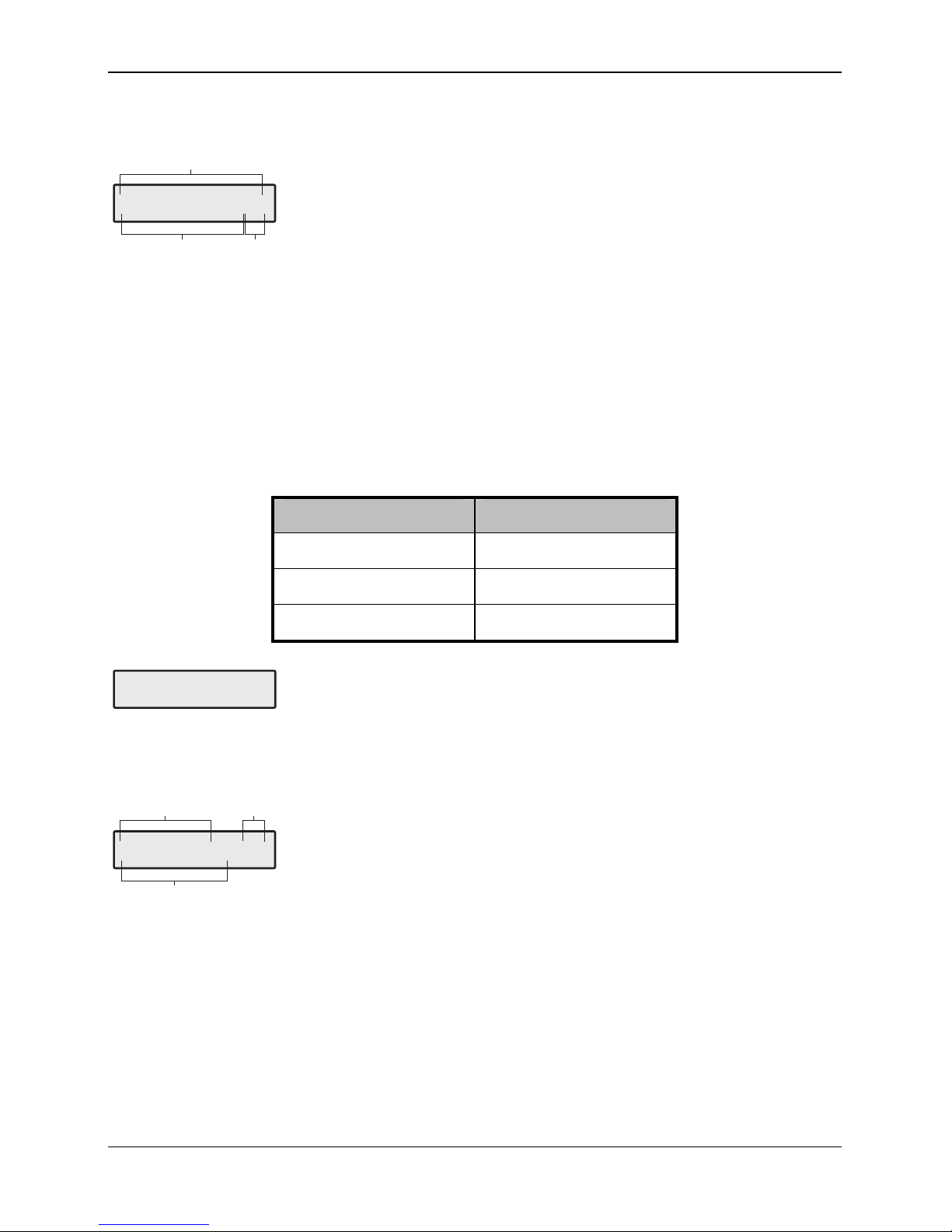
ID Biscuit Connections
The figure below shows both the old and newer iD Plus biscuits:
White
01
Blue
Yellow
Biscuit Number
Blue
Yellow
White
Biscuit Number
iD Plus Biscuit
Standard iD Biscuit
Yellow
Blue
White
= iD Loop +
= iD Loop -
= Alarm Switch
01
E
Each iD biscuit is identified by its own number 01 to 30 and contains its own internal
sensor which is continuously monitored by the expander module. The diagram below
shows the connections to the biscuit for monitoring both tamper and alarm contacts.
!
,

60IXD Installation Manual
INS261-3 7
iD Biscuit
Loop +
Loop -
Blue
Tamper
Yellow
Biscuit Number
Alarm
White
01
E
When the tamper switch is opened, the iD biscuit is taken offline and a tamper
condition is generated by the control panel. If the alarm switch is opened the biscuit's
internal sensor changes state and the control panel will see this as an active condition
and will respond as appropriate.
The diagram below shows the typical wiring of a biscuit to a standard PIR.
+12V
ALARM TAMPER
From Expander To next detector
Red
Black
Blue
Yellow
Red
Black
Blue
Yellow
White
Blue
Yellow
0V
01
E

60IXD Installation Manual
8 INS261-3
Commissioning and Testing
Programming the 60IXD Expander (Local Mode)
Once the 60IXD expander module has been installed, the following procedure must be
carried out in order to enable the module:
1. Enter into the Engineers Menu !"#$.
2. Select the UDL/Digi Options menu %and press &.
3. Select the Com Port Setup menu 'and press &.
4. Select Expansion Port option $.
5. Press (to change and select iD Module option ", followed by &to
accept.
6. Exit from the Expansion Port menu by pressing ).
7. Exit from the Com Port Setup menu by pressing ).
8. The Comms Led on the expander module should now be flashing.
9. Select the Engineer Utils menu *and press &.
10. Select the View iD Data menu +and press &.
11. Follow the flowchart on the next page for viewing and programming the iD
biscuit options.
12. Once the iD biscuits have been mapped to zones on the system you can now
program them as you would normal zones, refer to the “Zone Setup” menu in
the Premier 48/88/168/640 Installation Manual.
Viewing the iD Data (Local Mode)
As shown on the flowchart on the next page you can view the iD biscuit data that
expander is reporting to the control panel. There are two way of viewing the data from
the expander:
Normal Scan Mode
This is the normal operation mode of the expander and the data being displayed is the
average result of 4 successive scans of the iD loop.
Quick Scan Mode
In this mode the data being displayed is the result of each scan of the iD loop. This
mode is useful for identifying problems with biscuits due to interference, high
resistance connections etc.

60IXD Installation Manual
INS261-3 9
View iD Data Menu (Local Mode)
Yes
Engineer Utils
View iD Data
1111101010100011
..............1N
Area
Press to toggle between
iD Loop and
The status of the zones
will be displayed
0
12
iD Loop 1,01
Mapped Zone 000
YES to Select:-
Engineer Utils
Yes
Engineer Utils
View E ent Log
0
0000111001100111
..............2N
Press to toggle
between ormal loop scan
uick loop scan and
Biscuit Mapping
Area
N
Q
Press to editNo
the zone mapping and
wiring options.
????
No
Use keys 0 - 9 to enter
the zone number
Yes
iD Loop 1,01
Mapped Zone>000
iD Loop 1,01
Mapped Zone>010
iD Loop 1,01
Mapped Zone 010*
Press to toggle between
iD Loop and
Use keys to select the
required iD biscuit.
0
12.
Scroll
Omit
iD Loop 1,01
Mapped Zone>010*
Press to toggle between
Normally Open and Normally
Closed wiring.
* = Normally Open.
Omit
Menu
Notes
................
..............1N
1
23
Biscuits 01 to 16
Biscuits 17 to 30
Loop Number and Scan Mode
= Not Fitted/Tamper
= Healthy
= Active
= Loop 1
= Loop 2
= Normal scan mode
= Quick scan mode
.
1
0
1
2
N
Q
1
2
3
iD Loop 1,01
Mapped Zone 010*
1
23
iD Loop No, Biscuits No
Mapped Zone No
Wiring Type
* = Normally Open
1
2
3

60IXD Installation Manual
10 INS261-3
Programming the 60IXD Expander (Network Mode)
When installed in the Network Mode the Premier 60IXD expander module will report as
standard eight zone expanders. Each iD Biscuits is mapped to a particular expander
and zone:
Expander Expander Zones iD Loop iD Biscuits
1 1 - 8 1 01 - 08
2 1 - 8 1 09 - 16
3 1 - 8 1 17 - 24
4 1 - 6 1 25 - 30
5 1 - 8 2 01 - 08
6 1 - 8 2 09 - 16
7 1 - 8 2 17 - 24
8 1 - 6 2 25 - 30
1. Enter into the Engineers Menu !"#$.
2. Program the zones for the required type, see relevant Installation Manual.
3. Walk test/view zone status to check biscuit operation, see relevant Installation
Manual.
4. If you have an engineer’s keypad it can be plugged onto the Premier 60IXD for
local diagnostics.
Local Diagnostics using an Engineer’s Keypad
The local diagnostics menu can be accessed by plugging an engineer’s keypad onto
the Premier 60IXD. The following menus are available:
,- General Status
This menu shows the general status of the module and includes the number of biscuits
connected to each loop, tamper status and address details:
1
2
No of Biscuits on Loop 1
No of Active Biscuits on Loop 1
No of Reported Expanders (4 or 8)
No of Biscuits on Loop 2
No of Active Biscuits on Loop 2
Tamper Status (A=Active, H=Healthy)
3
4
5
6
iD 1=30,08 Add=8
iD 2=30,08 Tam=A
1 2 3
456
60IXD Installation Manual
INS261-3 11
!- Loop 1 Data
This menu shows the status of each biscuit connected to loop 1:
1
2
Biscuits 01 to 16
Biscuits 17 to 30
= Not Fitted/Tamper
= Healthy
= Active
Menu/Loop Number
= Loop 1
= Loop 2
.
1
0
1
2
3
1111111111111111
11001111000000>1
1
23
"- Loop 2 Data
This menu shows the status of each biscuit connected to loop 2 (see Loop 1).
#- Slow Scan Mode
This menu allows you to put the module into “Slow Scan Mode” which can be used to
measure the LOW, MID and HIGH states of the iD loop. For correct operation, the
voltages measured both at the module and at each biscuit should be as follows:
State Voltage
LOW 2.70V ±0.5V
MID 6.00V ±0.5V
HIGH 11.80V ±0.5V
iD Loop1=MID
iD Loop2=MID >3
Slow Scan Mode
Press [No] to change between LOW, MID and HIGH states.
$- Firmware Version and Voltage
This menu shows the firmware version and voltage level at the module:
1
2
3
Firmware Version
Voltage
Keypad Address (1 - 8; E=Engineer’s)
60iXD V2.0 >E
Voltage 13.7 >4
1
2
3

Specifications
Technical
Operating Voltage 10 - 13.7VDC
Current Consumption <100mA
Operating Temperature -10°C (+14°F) to +50°C (+122°F)
Storage Temperature -20°C (-4°F) to +60°C (+140°F)
Maximum Humidity 95% non-condensing
EMC Environment Residential, Commercial, Light Industrial or Industrial
Standards
The 60IXD conform to European Union (EU) Low Voltage Directive (LVD) 73/23/EEC
(amended by 93/68/EEC) and Electro-Magnetic Compatibility (EMC) Directive
89/336/EEC (amended by 92/31/EEC and 93/68/EEC).
The CE mark indicates that this product complies with the European requirements for
safety, health, environment and customer protection.
Warranty
All Texecom products are designed for reliable, trouble-free operation. Quality is
carefully monitored by extensive computerised testing. As a result the Premier 60IXD
expander is covered by a two-year warranty against defects in material or
workmanship. As the Premier 60IXD expander is not a complete alarm system but only
a part thereof, Texecom cannot accept responsibility or liability for any damages
whatsoever based on a claim that the Premier 60IXD expander failed to function
correctly. Due to our policy of continuous improvement Texecom reserve the right to
change specification without prior notice.
Premier is a trademark of Texecom Ltd.
Texecom Limited, Bradwood Court, St. Crispin Way, Haslingden, Lancashire BB4 4PW, England.
Technical Support:
UK Customers Tel: 08456 300 600
(Calls charged at 3.36 pence per minute from a BT landline. Calls from other networks may vary.)
International Customers Tel: +44 1278 411707
Email: techsupport@texe.com
© Texecom Limited 2007
INS261-3
Other manuals for premier 60ixd
1
Table of contents
Other Texecom Extender manuals


