Texim Europe GENE-BT05 User manual
SubCompact Board
G E N E - BT05
GENE-BT05
Intel®Celeron®N2930/N2807
Processor
With LVDS
10/100/1000Base-TXEthernet
2 Mini Card, LPC
1 USB3.0, 3 USB2.0, 4 COM
2CH HD Audio
GENE-BT05 Manual Rev. A 1st Ed.
June 19, 2014

SubCompact Board
G E N E - B T 0 5
i
Copyright Notice
This document is copyrighted, 2014. All rights are reserved. The
original manufacturer reserves the right to make improvements to the
products described in this manual at any time without notice.
No part of this manual may be reproduced, copied, translated, or
transmitted in any form or by any means without the prior written
permission of the original manufacturer. Information provided in this
manual is intended to be accurate and reliable. However, the original
manufacturer assumes no responsibility for its use, or for any in-
fringements upon the rights of third parties that may result from its
use.
The material in this document is for product information only and is
subject to change without notice. While reasonable efforts have been
made in the preparation of this document to assure its accuracy,
AAEON assumes no liabilities resulting from errors or omissions in
this document, or from the use of the information contained herein.
AAEON reserves the right to make changes in the product design
without notice to its users.

SubCompact Board
G E N E - B T 0 5
ii
Acknowledgments
All other products’name or trademarks are properties of their
respective owners.
AMI is a trademark of American Megatrends Inc.
CFast™is a trademark of the Compact Flash Association.
Intel®, Atom™, Celeron®are trademarks of Intel®Corporation.
Microsoft Windows®is a registered trademark of Microsoft Corp.
ITE is a trademark of Integrated Technology Express, Inc.
IBM, PC/AT, PS/2, and VGA are trademarks of International
Business Machines Corporation.
SoundBlaster is a trademark of Creative Labs, Inc.
Please be notified that all other products’name or trademarks not be
mentioned above are properties of their respective owners.

SubCompact Board
G E N E - B T 0 5
iii
Packing List
Before you begin installing your card, please make sure that the
following materials have been shipped:
GENE-BT05 CPU Card
DVD-ROM for manual (in PDF format) and drivers
If any of these items should be missing or damaged, please
contact your distributor or sales representative immediately.

SubCompact Board
G E N E - B T 0 5
iv
Contents
Chapter 1 General Information
1.1 Introduction................................................................ 1-2
1.2 Features .................................................................... 1-3
1.3 Specifications ............................................................1-4
Chapter 2 Quick Installation Guide
2.1 Safety Precautions.................................................... 2-2
2.2 Location of Connectors and Jumpers .......................2-3
2.3 Mechanical Drawing..................................................2-5
2.4 List of Jumpers..........................................................2-7
2.5 List of Connectors ..................................................... 2-8
2.6 Setting Jumpers ........................................................ 2-10
2.7 LVDS Port Backlight Inverter VCC Selection (JP1) .. 2-11
2.8 LVDS Port Backlight Lightness Control Mode Selection
(JP3)................................................................................ 2-11
2.9 LVDS Port Operating VDD Selection (JP4) ..............2-11
2.10 COM2 Pin8 Function Selection (JP8) .....................2-12
2.11 COM3 Pin8 Function Selection (JP9) ..................... 2-12
2.12 Auto Power Button Enable/Disable Selection (JP17)
.........................................................................................2-12
2.13 Front Panel Connector (JP19) ................................ 2-13
2.14 Touch Screen 4,5,8 Wire Selection (JP20)............. 2-14
2.15 Clear CMOS Jumper (JP21) ...................................2-14
2.16 +5VSB Output w/SMBus (CN1) ..............................2-14

SubCompact Board
G E N E - B T 0 5
v
2.17 LVDS Port Inverter / Backlight Connector (CN3)....2-15
2.18 +5V Output for SATA HDD (CN4)........................... 2-16
2.19 External +5VSB Input (CN5)...................................2-16
2.20 SATA Port1 (CN6)...................................................2-16
2.21 External +12V Input (CN7)...................................... 2-17
2.22 LVDS Port (CN8)..................................................... 2-17
2.23 Audio I/O Port (CN9) ............................................... 2-19
2.24 Mini-Card Slot (Half-Mini Card) (CN10) ..................2-20
2.25 LPC Port (CN11) .....................................................2-22
2.26 COM Port 2 (CN12)................................................. 2-23
2.27 LPT Port (CN13)......................................................2-26
2.28 COM Port 3 (CN14)................................................. 2-27
2.29 COM Port 4 (CN15)................................................. 2-30
2.30 Digital IO Port (CN16) .............................................2-30
2.31 USB 2.0 Port 3 (CN17)............................................ 2-31
2.32 USB 2.0 Port 2 (CN18)............................................ 2-32
2.33 BIOS Debug Port (CN19)........................................ 2-32
2.34 PS/2 Keyboard/Mouse Combo Port (CN22) ........... 2-33
2.35 Touch Screen Connector (CN23)............................ 2-33
2.36 CPU FAN (Optional) (CN24)...................................2-36
2.37 USB Ports 0 and 1 (CN25)......................................2-36
2.38 LAN (RJ-45) Port1 (CN26)......................................2-37
2.39 LAN (RJ-45) Port2 (CN27)...................................... 2-38
2.40 COM Port 1 (D-SUB 9) (CN28)............................... 2-39
2.41 HDMI Port (CN29)................................................... 2-39

SubCompact Board
G E N E - B T 0 5
vi
2.42 VGA Port (CN30)..................................................... 2-40
2.43 Battery (CN31) ........................................................ 2-41
2.44 CFast Slot (CN33)................................................... 2-41
2.45 DDR3L SO-DIMM Slot (CN34)................................ 2-43
2.46 UIM Card Socket (CN35) ........................................ 2-43
2.47 Mini-Card Slot (Full-Mini Card) (CN37)...................2-43
Chapter 3 AMI BIOS Setup
3.1 System Test and Initialization. .................................. 3-2
3.2 AMI BIOS Setup........................................................3-3
Chapter 4 Driver Installation
4.1 Installation ................................................................. 4-3
Appendix A Programming The Watchdog Timer
A.1 Watchdog Timer Registers ....................................A-2
A.2 Watchdog Sample Program...................................A-4
Appendix B I/O Information
B.1 I/O Address Map....................................................B-2
B.2 Memory Address Map............................................B-3
B.3 IRQ Mapping Chart................................................B-4
B.4 DMA Channel Assignments...................................B-6
Appendix C Mating Connector
C.1 List of Mating Connectors and Cables.................. C-2

SubCompact Board
G E N E - B T 0 5
vii
Appendix D Electrical Specifications for I/O Port
D.1 Electrical Specifications for I/O Port ..................... D-2

SubCompact Board
G E N E - B T 0 5
Chapter 1 General Information 1- 1
General
Information
Chapter
1

SubCompact Board
GENE- B T 0 5
Chapter 1 General Information 1- 2
1.1 Introduction
AAEON, a leading embedded boards manufacturer, is pleased to
announce the debut of their new generation 3.5” SubCompact
Board —GENE-BT05.
GENE-BT05 adopts Intel® Celeron® N2930/N2807 Processor.
The system memory is deployed with 204-pin SODIMM DDR3L
1066/1333 up to 8 GB. In addition, Intel®I211 supports two
10/100/1000Base-TX that allows a faster network connections.
The display of GENE-BT05 supports CRT/LCD, HDMI/ LCD
simultaneous and dual view displays. This model applies two Mini
Card and LPC bus for flexible expansions. Moreover, one SATA
3.0Gb/s, one CFastTM, and optional Half-size mSATA provide
ample storage. Three USB2.0, one USB3.0, four COM Ports (two
RS-232, two RS-232/422/485) and 8-bit digital I/O are configured
on the GENE-BT05 as well. Full functions make GENE-BT05 a
flexible and user friendly solution. This brand new SubCompact
board is developed to cater to the requirements of Automation,
Medical, ticket machine, transportation, gaming, KIOSK, and
POS/POI applications.

SubCompact Board
G E N E - B T 0 5
Chapter 1 General Information
1 - 3
1.2 Features
Onboard Intel® Celeron® N2930/N2807 Processor
DDR3L 1066/1333MHz SODIMM x 1, Up to 8 GB
Gigabit Ethernet x 2, RJ-45 x 2
CRT, 18/24-bit Dual-Channel LVDS LCD, HDMI
2CH HD Audio
SATA 3.0Gb/s x 1, CFast™ x 1
USB3.0 x 1, USB2.0 x 3, COM x 4, 8-bit Digital I/O
Mini Card x 2 (Full-size x 1, Half-size x 1)
+12V Only Operation
Onboard 4/5/8-wire Resistive Touch Screen Controller
(Optional)
AAEON Hi-Safe/SDK/Utility Supported
mSATA x 1 (Optional, Would Replace Mini Card Interface)
Onboard Trusted Platform Module (Optional)

SubCompact Board
GENE- B T 0 5
Chapter 1 General Information 1- 4
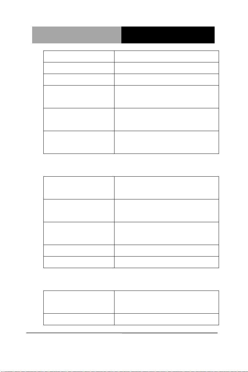
1.3 Specifications
System
Processor
Intel®
Celeron N2930/N2807
Processor
System Memory
204-pin DDR3L 1066/1333 MHz
SODIMM x 1, up to 8GB
Chipset
Intel® Celeron® series SoC
Processor
I/O Chipset
Fintek F81866D
Ethernet
Intel® I211, 10/100/1000Base-TX,
RJ-45 x 2
BIOS
AMI BIOS - 8MB SPI Flash
Wake on LAN
Yes
Watchdog Timer
Generates a time-out system reset
H/W Status
Monitoring
Supports power supply voltages
and temperature monitoring
Expansion
Interface
Mini Card x 2, LPC (Full-size x 1,
Half-size x 1)
Trusted Platform
Module
(TPM)
Atmel, AT97SC3204 (optional)
Battery
Lithium battery
Power
+12V, AT/ATX
SubCompact Board
G E N E - B T 0 5
Chapter 1 General Information
1 - 5
Requirement
Board Size
5.75" x 4" (146mm x 101.6mm)
Gross Weight
0.88 lb (0.4 kg)
Operating
Temperature
32°F ~ 140°F (0°C ~ 60°C)
Storage
Temperature
-40°F ~ 176°F (-40°C ~ 80°C)
Operating
Humidity
0% ~ 90% R/H, non-condensing
Display
Chipset
Intel® Celeron® series SOC
Processor
Memory
Shared system memory up to
512MB
Resolutions
Up to 2560 x 1600 for CRT, up to
1920 x 1200 for LCD, HDMI
LCD Interface
Up to 24-bit dual-channel LVDS x 1
HDMI
Up to 1920x1080 @ 60 Hz
I/O
Storage
SATA 3.0Gb/s x 1, CFast™ x 1,
Half-size mSATA x 1(Optional)
Serial Port
RS-232 x 2, RS-232/422/485 (auto

SubCompact Board
GENE- B T 0 5
Chapter 1 General Information 1- 6
flow) x 2
USB
USB3.0 x 1, USB2.0 x 3
PS/2 Port
Keyboard x 1, Mouse x 1
Digital I/O
Supports 8-bit (Programmable)
Audio
Line-in, Line-out, Mic-in
Touch Screen
Support 4/5/8-wire resistive touch
screen (optional)

SubCompact Board
G E N E - B T 0 5
Chapter 2 Quick Installation Guide 2-1
Quick
Installation
Guide
Chapter
2

SubCompact Board
G E N E - B T 0 5
Chapter 2 Quick Installation Guide 2-2
2.1 Safety Precautions
Always completely disconnect the power cord
from your board whenever you are working on
it. Do not make connections while the power is
on, because a sudden rush of power can
damage sensitive electronic components.
Always ground yourself to remove any static
charge before touching the board. Modern
electronic devices are very sensitive to static
electric charges. Use a grounding wrist strap at
all times. Place all electronic components on a
static-dissipative surface or in a static-shielded
bag when they are not in the chassis
SubCompact Board
G E N E - B T 0 5
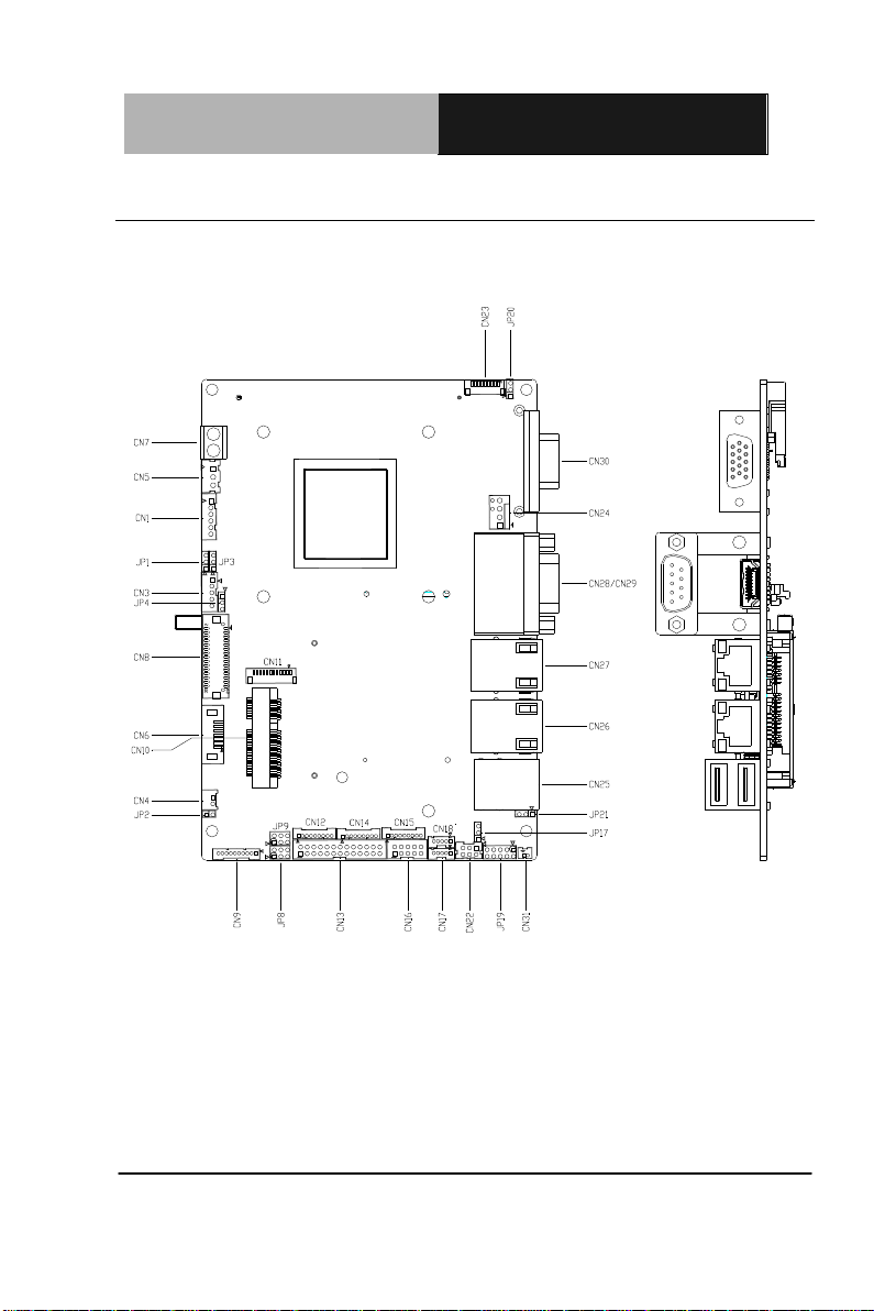
Chapter 2 Quick Installation Guide 2-3
2.2 Location of Connectors and Jumpers
Component Side
SubCompact Board
G E N E - B T 0 5
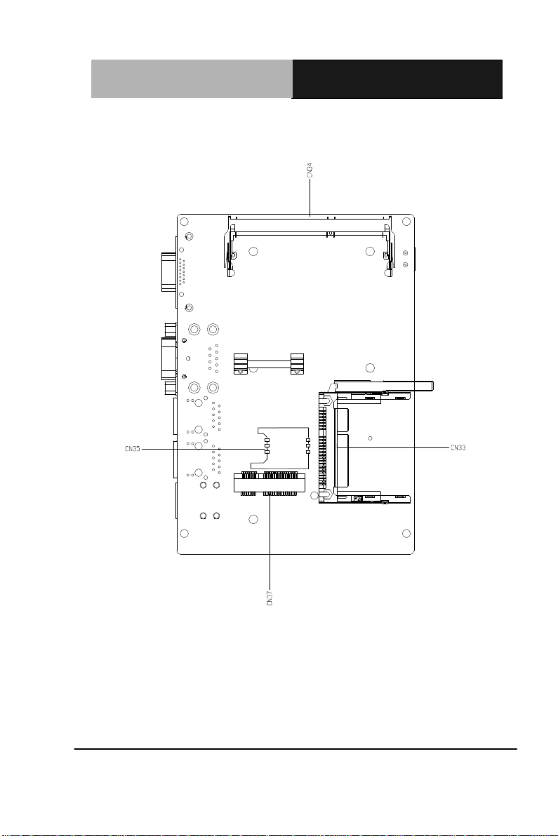
Chapter 2 Quick Installation Guide 2-4
Solder Side

SubCompact Board
G E N E - B T 0 5
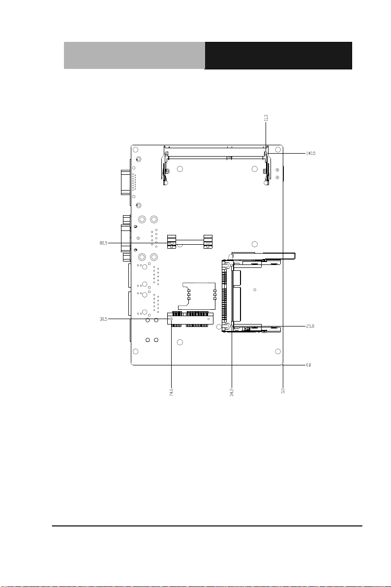
Chapter 2 Quick Installation Guide 2-5
2.3 Mechanical Drawing
Component Side
SubCompact Board
G E N E - B T 0 5
Chapter 2 Quick Installation Guide 2-6
Solder Side
Table of contents


