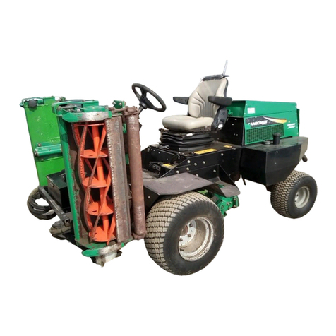
TR A C TOR
Tires ................................ 18 x 9.5 - 8 tubeles s
P res s ure: ......................... 8-12 psi (55-83 kPa)
B attery:
Type........................... 12 Volt Lead/Acid
G roup ............. ......... .. 22 G MF
Parking B rake .................. Mechanical front drum brakes
Hand lever actuated
S peed:
Mow ......................... 0 - 3.7 mph (5.9 kph)
Transport .................. 0 - 6.6 mph (10.6 kph)
R everse..................... 0 - 3.5 mph (5.6 kph)
Hydraulic S ystem:
C apacity.......................... 5 U.S . gal. (19 liters ) S ystem
F luid Type ....... .......... ...... G reens C are 46 B iodegradable
F ilter.......... .......... ......... ... F ull F low 20 micron
S teering ......................... Hydrostatic power steering
Mower Lift ....................... Hydraulic Double Acting C ylinders
WE IG HT S AND DIME NS IOS
Dimens ions : Inches (mm)
Length - G ras s C atchers On ........................ 99.5 (2526)
Height - S teering W heel Up ......................... 51.5 (1308)
Wheel B as e............ ...................................... 52.8 (1341)
Width - Transport Position ............................... 68 (1727)
Width - Mowing Pos ition.................................. 70 (1778)
Width - W heel .............................................. 50.5 (1283)
Turning R adius ................................................ 18 (457)
Weights : L bs . (kg)
Working Weight Less Operator
62287 .......................................................... 1150 (522)
62288 .......................................................... 1150 (522)
62289 .......................................................... 1340 (609)
AC C E S S OR IE S & S UP POR T L IT E R AT UR E
C ontact your area Textron Turf C are And S pecialty P roducts Dealer for a complete listing of acces s ories and
attachments.
Acces s ories
Air Blow Gun...........................................................JAC5098
Orange Touch-up Paint (12 oz. s pray)....................... 554598
Arm R est..................................................................... 66156
Grass Catcher............................................................. 67891
B rus h, 62”................................................................... 68623
Fine Bristle Brush........................................................ 68536
G reen S entry II Oil S ys tem Monitor ....... ......... ......... ... 68606
Light Kit................................................................... 2811910
Mounting K it
R ear R oller C leaner .................................................... 68595
Quick R oller (S et of 3)................................................. 68662
Spiker (Set of 3) .......................................................... 68663
Traction T ire (S et of 2)................................................. 62616
Turf G roomer 1/4” S pacing R .H. (2 R equired)............. 67870
Turf G roomer 1/4” S pacing L.H. (1 R equired) ............. 67871
Turf G roomer 1/2” S pacing R .H. (2 R equired)............. 67872
Turf G roomer 1/2” S pacing L.H. (1 R equired) ............. 67873
Vertical Mower L.H. (1 R equired) ................................ 68549
Vertical Mower R .H. (2 R equired) ............................... 68550
R eels
5 B lade R eel L.H. (1 R equired).................................... 68586
5 B lade R eel R .H. (2 R equired) ................................... 68587
7 B lade R eel L.H. (1 R equired).................................... 68588
7 B lade R eel R .H. (2 R equired) ................................... 68589
9 B lade R eel L.H. (1 R equired).................................... 68599
9 B lade R eel R .H. (2 R equired) ................................... 68600
11 B lade R eel L.H. (1 R equired).................................. 68621
11 B lade R eel R .H. (2 R equired) ................................. 68622
R ollers
G rooved Front R oller .......... ........................ ............. .... 68527
S olid R oller ................................................................. 68530
High C ut R oller 3/4 in................................................... 68594
G rooved Front R oller (S teel) . ......... ......... .............. ....... 68613
G rooved Front R oller (Aluminum) ................ ................ 68614
G rooved R ear R oller .................................................... 68580
S upport L iterature
S afety & Operation Manual...................................... 2811456
Parts & Maintenance Manual................................... 2811457
Diesel E ngine Parts C atalog.................................... 3004386
Opera tor Training V ideo . ......... ........... ............... ....... 5001525
S ervice & R epair Manual
C AUTION
Use of other than Textron Turf C are And S pecialty P roducts authorized parts and acces sories may cause personal
injury or damage to the equipment and will void the warranty
!

