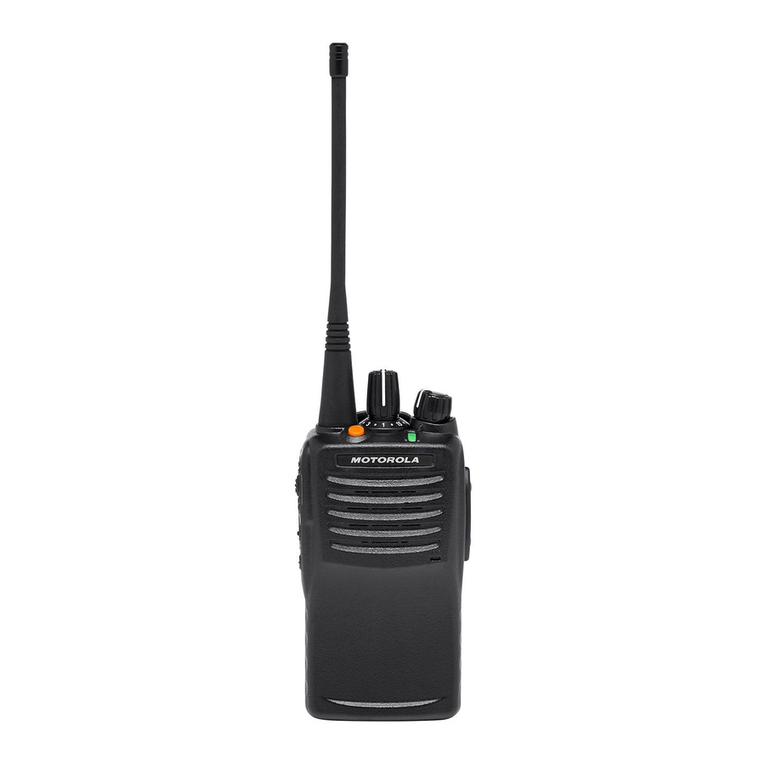
Thales AN/PRC-148 Setup guide

OPERATION AND MAINTENANCE INSTRUCTIONS
WITH ILLUSTRATED PARTS BREAKDOWN
ORGANIZATIONAL LEVEL
AN/PRC-148(V)(C)
MULTIBAND INTER/INTRA TEAM RADIO
(INCLUDES SINCGARS, HAVEQUICK, ANDVT, RETRANSMISSION)
THALES COMMUNICATIONS, INC.
22605 GATEWAY CENTER DRIVE
CLARKSBURG, MD 20871
COPYRIGHT : JUNE 1999
THALES COMMUNICATIONS, INC.
PUBLISHED AND CONFIDENTIAL WORK
ALL RIGHTS RESERVED
CONFIGURATION NOTICE: This document contains technical information pertinent to the THALES PRC6991 MULTIBAND RADIO SET.
The information contained herein is for the support of the THALES PRC6991 MULTIBAND RADIO SET.
PROPRIETARY NOTICE: This document contains information proprietary to THALES COMMUNICATIONS, INC. It is furnished for
operation and support purposes only and not for reprocurement. All reprocurement and manufacturing rights are expressly reserved by THALES
COMMUNICATIONS, INC., and no such use may be made of this document, either directly or indirectly without the prior written consent of
THALES COMMUNICATIONS, INC.
OCTOBER 9, 2002


FRONT MATTER
i
TABLE OF CONTENTS
CHAPTER PAGE
LIST OF FIGURES.................................................................................................................................................. IV
LIST OF TABLES.................................................................................................................................................... VI
SAFETY SUMMARY .............................................................................................................................................VII
FOREWORD ......................................................................................................................................................... VIII
CHAPTER 1 GENERAL INFORMATION .................................................................................................... 1-1
1.1 MBITR DESCRIPTION ............................................................................................................................. 1-1
1.1.1 Receiver-Transmitter Unit ................................................................................................................. 1-1
1.1.2 Batteries ............................................................................................................................................. 1-2
1.1.3 Holster and Accessory Carrying Bag................................................................................................. 1-2
1.1.4 Antennas ............................................................................................................................................ 1-2
1.1.5 Audio/Keyfill Adapter Device........................................................................................................... 1-3
1.2 ACCESSORIES .......................................................................................................................................... 1-3
1.2.1 Audio Accessories ............................................................................................................................. 1-3
1.2.2 Antennas ............................................................................................................................................ 1-4
1.2.3 Vehicle Adapter ................................................................................................................................. 1-4
1.2.4 Special Power Adapter Interface (SPAI) ........................................................................................... 1-4
1.2.5 Battery Chargers ................................................................................................................................ 1-4
1.2.6 PC-based Radio Programmer............................................................................................................. 1-4
1.2.7 Cables ................................................................................................................................................ 1-5
1.3 TRANSCEIVER CHARACTERISTICS ........................................................................................................... 1-6
1.3.1 Transmitter Characteristics ................................................................................................................ 1-6
1.3.2 Receiver Characteristics .................................................................................................................... 1-6
1.4 COMMUNICATION SECURITY (COMSEC) ............................................................................................... 1-6
1.4.1 Compatibility ..................................................................................................................................... 1-7
1.4.2 Tone Squelch Disable ........................................................................................................................ 1-7
1.4.3 Encryption Device Keying................................................................................................................. 1-7
1.4.4 TEMPEST ......................................................................................................................................... 1-7
1.4.5 Algorithms ......................................................................................................................................... 1-7
1.4.6 Cryptographic Key Storage................................................................................................................ 1-7
1.4.7 Zeroization......................................................................................................................................... 1-7
1.4.8 Key Retention .................................................................................................................................... 1-7
1.4.9 Fade Bridging .................................................................................................................................... 1-7
1.4.10 Initial Synchronization.................................................................................................................. 1-8
1.5 SINCGARS TRANSMISSION SECURITY (TRANSEC) ............................................................................. 1-8
1.5.1 Frequency Range ............................................................................................................................... 1-8
1.5.2 Operating Modes ............................................................................................................................... 1-8
1.5.3 Squelch Tones.................................................................................................................................... 1-8
1.5.4 SINCGARS Electronic Counter Counter-Measures (ECCM) Remote Fill (ERF) ............................ 1-8
1.5.5 Encryption Device Keying................................................................................................................. 1-8
1.6 HAVEQUICK I/II TRANSMISSION SECURITY ......................................................................................... 1-9
1.6.1 Frequency Range ............................................................................................................................... 1-9
1.6.2 Interoperability .................................................................................................................................. 1-9
1.6.3 Over-the-Air Time of Day ................................................................................................................. 1-9
1.6.4 Squelch Tones.................................................................................................................................... 1-9
1.6.5 COMSEC Compatibility.................................................................................................................... 1-9
1.6.6 Net Support........................................................................................................................................ 1-9

FRONT MATTER
ii
1.7 ANDVT OPERATION............................................................................................................................... 1-9
1.7.1 Frequency Range ............................................................................................................................. 1-10
1.7.2 Channel Bandwidth ......................................................................................................................... 1-10
1.7.3 Interoperability ................................................................................................................................ 1-10
1.7.4 Operating Modes ............................................................................................................................. 1-10
CHAPTER 2 OPERATING INSTRUCTIONS ............................................................................................... 2-1
2.1 CONTROLS,INDICATORS,AND CONNECTORS .......................................................................................... 2-1
2.1.1 Controls ............................................................................................................................................. 2-1
2.1.2 Indicators ........................................................................................................................................... 2-3
2.1.3 Connectors ......................................................................................................................................... 2-3
2.2 OPERATING PROCEDURES ....................................................................................................................... 2-5
2.2.1 MBITR Channels and Groups ........................................................................................................... 2-5
2.2.2 Display Menus................................................................................................................................... 2-5
2.2.3 PROGRAMMING Menu................................................................................................................. 2-10
2.2.4 SCAN............................................................................................................................................... 2-28
2.2.5 Cloning Operation ........................................................................................................................... 2-31
2.2.6 Digital Data Operation..................................................................................................................... 2-32
2.2.7 Expedient Retransmission................................................................................................................ 2-33
CHAPTER 3 PRINCIPLES OF OPERATION............................................................................................... 3-1
3.1 GENERAL................................................................................................................................................. 3-1
3.2 FUNCTIONAL SYSTEM(S)OPERATION...................................................................................................... 3-1
3.2.1 Transceiver Module ........................................................................................................................... 3-2
3.2.2 Control/Crypto CCA.......................................................................................................................... 3-2
3.2.3 Radio Systems Module ...................................................................................................................... 3-2
3.2.4 Rechargeable Lithium Ion Battery..................................................................................................... 3-3
3.2.5 Non-Rechargeable Battery Holder..................................................................................................... 3-3
3.3 30-512 MHZ TRANSCEIVER MODULE ..................................................................................................... 3-3
3.3.1 Receiver/Synthesizer CCA ................................................................................................................ 3-4
3.3.2 Transmit CCA.................................................................................................................................... 3-4
3.4 CONTROL/CRYPTO CIRCUIT CARD ASSEMBLY (CCA) ............................................................................ 3-6
3.4.1 Microcontroller .................................................................................................................................. 3-6
3.4.2 Cryptographic Module....................................................................................................................... 3-6
3.4.3 RED DSP........................................................................................................................................... 3-6
3.4.4 BLACK DSP ..................................................................................................................................... 3-6
3.4.5 FPGA ................................................................................................................................................. 3-8
3.4.6 Power management............................................................................................................................ 3-8
3.5 FRONT PANEL CCA................................................................................................................................. 3-8
3.6 CHASSIS ASSEMBLY .............................................................................................................................. 3-10
CHAPTER 4 MAINTENANCE........................................................................................................................ 4-1
4.1 GENERAL................................................................................................................................................. 4-1
4.2 OPERATIONAL CHECKOUT. ..................................................................................................................... 4-1
4.3 RADIO PREVENTIVE MAINTENANCE........................................................................................................ 4-1
4.4 BATTERY PREVENTIVE MAINTENANCE ................................................................................................... 4-1
4.5 TROUBLESHOOTING................................................................................................................................. 4-2
4.6 REMOVAL/REPLACEMENT PROCEDURES -OPERATOR............................................................................. 4-4
4.6.1 Audio Accessory Removal/Replacement (Urban version). ............................................................... 4-4
4.6.2 Audio Accessory Removal/Replacement (Maritime version). .......................................................... 4-5
4.6.3 Antenna Removal/Replacement......................................................................................................... 4-5
4.6.4 Battery Removal/Replacement. ......................................................................................................... 4-5
4.7 WATERTIGHT INTEGRITY ........................................................................................................................ 4-6

FRONT MATTER
iii
CHAPTER 5 ILLUSTRATED PARTS BREAKDOWN ................................................................................ 5-1
5.1 GENERAL................................................................................................................................................. 5-1
5.2 MAINTENANCE PARTS LIST..................................................................................................................... 5-1
5.3 NUMERICAL INDEX.................................................................................................................................. 5-2
5.4 ELECTROSTATIC DISCHARGE (ESD) SENSITIVE DEVICES........................................................................ 5-3
5.5 CAGE CODE SUMMARY. ........................................................................................................................ 5-3
CHAPTER 6 MBITR VEHICLE ADAPTER ................................................................................................. 6-1
6.1 GENERAL................................................................................................................................................. 6-1
6.2 PHYSICAL CHARACTERISTICS.................................................................................................................. 6-1
6.2.1 Equipment Description ...................................................................................................................... 6-1
6.2.2 Weight ............................................................................................................................................... 6-2
6.2.3 Dimensions ........................................................................................................................................ 6-2
6.2.4 Temperature....................................................................................................................................... 6-2
6.3 ELECTRICAL CHARACTERISTICS.............................................................................................................. 6-2
6.4 INSTALLATION......................................................................................................................................... 6-2
6.4.1 Mechanical Installation...................................................................................................................... 6-2
6.4.2 Electrical Connections ....................................................................................................................... 6-2
6.5 OPERATION ............................................................................................................................................. 6-2
6.6 MAINTENANCE ........................................................................................................................................ 6-3
6.7 ILLUSTRATIONS ....................................................................................................................................... 6-3
6.8 PARTS LIST.............................................................................................................................................. 6-3
CHAPTER 7 SPECIAL POWER ADAPTER INTERFACE (SPAI)............................................................ 7-1
7.1 GENERAL................................................................................................................................................. 7-1
7.2 PHYSICAL CHARACTERISTICS.................................................................................................................. 7-1
7.3 ELECTRICAL CHARACTERISTICS.............................................................................................................. 7-1
7.3.1 Electrical Protection........................................................................................................................... 7-1
7.4 OPERATION ............................................................................................................................................. 7-2
7.4.1 Indicators ........................................................................................................................................... 7-2
7.5 PERFORMANCE ........................................................................................................................................ 7-3
CHAPTER 8 BATTERY CHARGERS............................................................................................................ 8-1
8.1 GENERAL................................................................................................................................................. 8-1
8.2 PHYSICAL CHARACTERISTICS.................................................................................................................. 8-1
8.2.1 Weight and Dimensions..................................................................................................................... 8-1
8.2.2 Temperature....................................................................................................................................... 8-1
8.3 ELECTRICAL CHARACTERISTICS.............................................................................................................. 8-1
8.3.1 Single Unit Charger. .......................................................................................................................... 8-1
8.3.2 Six (6) Unit Chargers......................................................................................................................... 8-2
8.4 PERFORMANCE ........................................................................................................................................ 8-2
8.5 OPERATING INDICATIONS ........................................................................................................................ 8-2
8.6 ILLUSTRATIONS ....................................................................................................................................... 8-4
CHAPTER 9 DEFINITIONS ............................................................................................................................ 9-1
9.1 DEFINITIONS............................................................................................................................................ 9-1
9.1.1 Active Channel .................................................................................................................................. 9-1
9.1.2 Channel.............................................................................................................................................. 9-1
9.1.3 CTCSS Tone...................................................................................................................................... 9-1
9.1.4 Electronic Remote Fill ....................................................................................................................... 9-1
9.1.5 Fade Bridge........................................................................................................................................ 9-1
9.1.6 Hopset................................................................................................................................................ 9-1
9.1.7 Initial Synchronization....................................................................................................................... 9-1
9.1.8 Lockout Set........................................................................................................................................ 9-1
9.1.9 Multiple Word of Day (MWOD)....................................................................................................... 9-1

FRONT MATTER
iv
9.1.10 Offset ............................................................................................................................................ 9-1
9.1.11 Open Channel................................................................................................................................ 9-2
9.1.12 Priority Scan.................................................................................................................................. 9-2
9.1.13 Repeater Delay.............................................................................................................................. 9-2
9.1.14 Scan Revert Channel..................................................................................................................... 9-2
9.1.15 Selected Channel........................................................................................................................... 9-2
9.1.16 Time of Day (TOD) ...................................................................................................................... 9-2
9.1.17 Transmit (TX) Timeout................................................................................................................. 9-2
9.1.18 Word of Day (WOD) .................................................................................................................... 9-2
9.1.19 Working Group ............................................................................................................................. 9-2
INDEX ..........................................................................................................................................................................1
LIST OF FIGURES
FIGURE 1-1 MBITR UNIT (URBAN)WITH BATTERY ................................................................................................... 1-0
FIGURE 2-1 MBITR KEYPAD ..................................................................................................................................... 2-1
FIGURE 2-2 MBITR CONTROLS AND CONNECTORS (SHEET 1)................................................................................... 2-2
FIGURE 2-3 MBITR CONTROLS AND CONNECTORS (SHEET 2)................................................................................... 2-4
FIGURE 2-4 MBITR AUDIO/KEYFILL CONNECTOR PIN-OUT...................................................................................... 2-4
FIGURE 2-5 DEFAULT DISPLAY SCREEN ..................................................................................................................... 2-6
FIGURE 2-6 BASIC ALTERNATE DEFAULT DISPLAY.................................................................................................... 2-6
FIGURE 2-7 SINCGARS ALTERNATE DISPLAY (SC) ................................................................................................. 2-7
FIGURE 2-8 SINCGARS ALTERNATE DISPLAY (FH) ................................................................................................. 2-7
FIGURE 2-9 HAVEQUICK SC ALTERNATE DISPLAY ................................................................................................ 2-7
FIGURE 2-10 HAVEQUICK FH ALTERNATE DISPLAY .............................................................................................. 2-7
FIGURE 2-11 ANDVT ALTERNATE DISPLAY............................................................................................................. 2-8
FIGURE 2-12 RECEIVE SCREEN................................................................................................................................... 2-8
FIGURE 2-13 TRANSMIT SCREEN ................................................................................................................................2-8
FIGURE 2-14 SQUELCH ADJUST SCREEN..................................................................................................................... 2-8
FIGURE 2-15 MODE SELECT SCREEN .......................................................................................................................... 2-9
FIGURE 2-16 EMERGENCY BEACON SELECT............................................................................................................... 2-9
FIGURE 2-17 GPS TRANSMIT ................................................................................................................................... 2-10
FIGURE 2-18 GROUP SELECT SCREEN....................................................................................................................... 2-10
FIGURE 2-19 MAIN MENU SCREEN........................................................................................................................... 2-10
FIGURE 2-20 INITIAL ZEROIZE SCREEN.................................................................................................................. 2-10
FIGURE 2-21 CLEAR ALL SCREEN ......................................................................................................................... 2-11
FIGURE 2-22 COMSEC ZEROIZE ............................................................................................................................. 2-11
FIGURE 2-23 COMSEC ZEROIZE ALL ...................................................................................................................... 2-11
FIGURE 2-24 COMSEC SELECTIVE ZEROIZE ........................................................................................................... 2-11
FIGURE 2-25 TRANSEC ZEROIZE SCREEN .............................................................................................................. 2-12
FIGURE 2-26 RADIO PARAMETERS ZEROIZE SCREEN ............................................................................................... 2-12
FIGURE 2-27 KEY FILL MAIN SCREEN...................................................................................................................... 2-12
FIGURE 2-28 COMSEC KEYFILL ............................................................................................................................. 2-13
FIGURE 2-29 TRANSEC FILL SCREEN..................................................................................................................... 2-14
FIGURE 2-30 MODE 2/3 KEY FILL ........................................................................................................................... 2-14
FIGURE 2-31 TOD SELECTION SCREEN ................................................................................................................... 2-15
FIGURE 2-32 TOD FILL SCREEN .............................................................................................................................. 2-15
FIGURE 2-33 TOD RX SCREEN................................................................................................................................2-15
FIGURE 2-34 TOD TX SCREEN................................................................................................................................2-15
FIGURE 2-35 MWOD-A SCREEN............................................................................................................................. 2-15
FIGURE 2-36 MWOD-M SCREEN ............................................................................................................................ 2-16

FRONT MATTER
v
FIGURE 2-37 OPR DAY SCREEN ............................................................................................................................. 2-16
FIGURE 2-38 WOD FILL SCREEN ........................................................................................................................... 2-16
FIGURE 2-39 MWOD FILL SCREEN (1) .................................................................................................................. 2-16
FIGURE 2-40 MWOD FILL SCREEN (2) .................................................................................................................. 2-16
FIGURE 2-41 WOD FILL SCREEN (3)...................................................................................................................... 2-17
FIGURE 2-42 FMT FILL SCREEN............................................................................................................................. 2-17
FIGURE 2-43 LOCKOUT SET ERF.............................................................................................................................2-18
FIGURE 2-44 HOPSET ERF....................................................................................................................................... 2-18
FIGURE 2-45 INITIAL PROGRAMMING SCREEN ......................................................................................................... 2-19
FIGURE 2-46 RESTRICTED ACCESS SCREEN.............................................................................................................. 2-19
FIGURE 2-47 GLOBAL PROGRAMMING SCREEN ........................................................................................................ 2-19
FIGURE 2-48 TRANSMIT TIMEOUT SCREEN .............................................................................................................. 2-20
FIGURE 2-49 BACKLIGHT TIMEOUT SCREEN ............................................................................................................ 2-20
FIGURE 2-50 SET CLOCK SCREEN............................................................................................................................. 2-20
FIGURE 2-51 SIDE CONNECTOR ENABLE ................................................................................................................. 2-20
FIGURE 2-52 RADIO CONFIG SCREEN................................................................................................................... 2-20
FIGURE 2-53 BASIC CHANNEL PROGRAMMING SCREENS ......................................................................................... 2-22
FIGURE 2-54 SINCGARS CHANNEL SCREENS ......................................................................................................... 2-23
FIGURE 2-55 HAVEQUICK CHANNEL SCREENS ..................................................................................................... 2-24
FIGURE 2-56 ANDVT CHANNEL SCREENS .............................................................................................................. 2-25
FIGURE 2-57 GROUP PROGRAMMING SCREEN .......................................................................................................... 2-26
FIGURE 2-58 SA PROGRAMMING.............................................................................................................................. 2-27
FIGURE 2-59 EMERGENCY PROGRAMMING SCREEN ................................................................................................. 2-27
FIGURE 2-60 BEACON PROGRAMMING ..................................................................................................................... 2-27
FIGURE 2-61 RADIO MAINTENANCE SCREEN ........................................................................................................... 2-27
FIGURE 2-62 BUILT-IN-TEST SCREEN....................................................................................................................... 2-27
FIGURE 2-63 CHECK CLOCK SCREEN ....................................................................................................................... 2-27
FIGURE 2-64 DISPLAY ELAPSED TIME SCREEN......................................................................................................... 2-28
FIGURE 2-65 OPTIONS ENABLED SCREEN................................................................................................................. 2-28
FIGURE 2-66 SCAN OPERATION SCREEN................................................................................................................. 2-29
FIGURE 2-67 ACTIVE SCAN SCREEN ....................................................................................................................... 2-29
FIGURE 2-68 PRIORITY CHANNEL ASSIGNMENT....................................................................................................... 2-29
FIGURE 2-69 SELECT SCAN PLAN ........................................................................................................................... 2-30
FIGURE 2-70 CONFIGURE SCAN SCREEN................................................................................................................. 2-30
FIGURE 2-71 DATA OPERATION SCREEN ................................................................................................................. 2-32
FIGURE 2-72 RETRANS ENABLED ......................................................................................................................... 2-33
FIGURE 3-1 RADIO SET,SIMPLIFIED BLOCK DIAGRAM .............................................................................................. 3-1
FIGURE 3-2 TRANSCEIVER MODULE BLOCK DIAGRAM .............................................................................................. 3-5
FIGURE 3-3 CONTROL/CRYPTO BLOCK DIAGRAM ...................................................................................................... 3-7
FIGURE 3-4 FRONT PANEL BLOCK DIAGRAM ............................................................................................................. 3-9
FIGURE 5-1 MULTIBAND INTER/INTRA TEAM RADIO SYSTEM (AN/PRC-148(V)(C))................................................ 5-6
FIGURE 5-2 MBITR RECEIVER-TRANSMITTER UNIT (RTU) ...................................................................................... 5-9
FIGURE 6-1 RCH ........................................................................................................................................................ 6-3
FIGURE 6-2 MBITR VEHICLE ADAPTER..................................................................................................................... 6-3
FIGURE 7-1 SPAI CONNECTIONS................................................................................................................................7-3
FIGURE 8-1 MBITR SINGLE CHARGER....................................................................................................................... 8-4
FIGURE 8-2 MBITR MULTI-CHARGER ....................................................................................................................... 8-4

FRONT MATTER
vi
LIST OF TABLES
TABLE 1-1 PHYSICAL CHARACTERISTICS ................................................................................................................... 1-1
TABLE 1-2 CONTINUOUS TONE CONTROLLED SQUELCH SYSTEM (CTCSS) AVAILABLE TONES (IN HZ) ................... 1-6
TABLE 2-1 KEY ASSIGNMENTS TABLE ....................................................................................................................... 2-1
TABLE 2-2 GLOBAL OPTIONS ................................................................................................................................... 2-19
TABLE 2-3 CHANNEL OPTIONS (BASIC).................................................................................................................... 2-21
TABLE 2-4 CHANNEL OPTIONS (SINCGARS).......................................................................................................... 2-23
TABLE 2-5 CHANNEL OPTIONS (HAVEQUICK)...................................................................................................... 2-24
TABLE 2-6 GROUP OPTIONS ..................................................................................................................................... 2-26
TABLE 4-1 BUILT-IN TEST RESULTS.......................................................................................................................... 4-1
TABLE 4-2 OPERATOR TROUBLESHOOTING GUIDE.................................................................................................... 4-2
TABLE 5-1 MBITR ACCESSORY EQUIPMENT ............................................................................................................. 5-4
TABLE 5-2 MULTIBAND INTER/INTRA TEAM RADIO SYSTEM,20 METER (AN/PRC-148 (V)1(C))............................. 5-7
TABLE 5-3 MULTIBAND INTER/INTRA TEAM RADIO SYSTEM,2METER (AN/PRC-148 (V)2(C))............................... 5-8
TABLE 5-4 MBITR UNIT,20 METER (4101104-501) ............................................................................................... 5-10
TABLE 5-5 MBITR UNIT,2METER (4101195-501) ................................................................................................. 5-11
TABLE 6-1 PARTS LIST,MA6943............................................................................................................................... 6-3
TABLE 8-1 BATTERY CHARGER WEIGHTS AND DIMENSIONS ..................................................................................... 8-1
TABLE 8-2 OPERATING AND STORAGE TEMPERATURES ............................................................................................. 8-1
TABLE 8-3 CHARGER PERFORMANCE ......................................................................................................................... 8-2
TABLE 8-4 CHARGE STATUS INDICATORS .................................................................................................................. 8-2

FRONT MATTER
vii
SAFETY SUMMARY
The following are general safety precautions that are not related to any specific procedure, and
do not appear elsewhere in this manual. These Safety Summaries are recommended precautions
that all personnel must understand and apply during any given phase of operation and
maintenance. Each chapter has other specific warnings and cautions.
KEEP AWAY FROM LIVE CIRCUITS
Personnel must at all times observe all safety regulations. Do not replace
components or make adjustments inside equipment with power turned on. Under
certain conditions, dangerous voltages may exist when the power switch is in the
off position due to charges retained by capacitors. To avoid injury, always
remove power and discharge and ground a circuit before touching it.
VOLTAGES WITHIN THIS EQUIPMENT ARE HIGH ENOUGH TO
ENDANGER LIFE.
(Applies to battery chargers only)
Covers are not to be removed except by persons qualified and authorized to do so
and these persons should always take extreme care once the covers have been
removed.
HAZARDS OF ELECTROMAGNETIC RADIATION TO ORDNANCE (HERO)
DO NOT operate the radio within 10 feet (3 meters) of any type of fuzed
ordnance. Operating the radio in close proximity to ordnance MAY induce or
otherwise couple currents and/or voltages of magnitudes large enough to initiate
electroexplosive devices or other sensitive explosive components of weapon
systems, ordnance, or explosive devices.
CAUTION - LITHIUM ION BATTERIES
Li-ion batteries have a very high energy density. Exercise precaution when
handling and testing. Do not short circuit, overcharge, crush, mutilate, nail
penetrate, apply reverse polarity, expose to high temperature or disassemble. High
case temperature resulting from abuse of the cell could cause physical injury.

FRONT MATTER
viii
FOREWORD
NOTE: THIS MANUAL CONTAINS INFORMATION THAT IS CURRENT AS OF
THE DATE SHOWN ON THE FRONT COVER. ADDITIONAL FUNCTIONALITY IS
BEING DEVELOPED FOR THE RADIO AND THE APPEARANCE OF OPERATING
SCREENS IS SUBJECT TO CHANGE FROM THOSE SHOWN HEREIN.
The radio operation (man-machine interface) shown in this manual reflects radio software
Revision U, Version 2.28 and PC Programmer Revion D, Version 1.03. Some screens may not
correspond to those in earlier radio software or PC Programmer versions.
Conventions used in this manual: Words and symbols shown in brackets [ ] correspond to the
markings shown on the radio keys.
This manual for the Multiband Inter/Intra Team Radio (MBITR) and its associated accessories
meets the technical content requirements of Contract USZA22-97-D-0019, Statement of Work,
Attachment 1, COTS Manual Evaluation Checklist and MIL-HDBK-1221.
a. Chapter 1 - General Information. This chapter provides general information for the
MBITR including equipment description and purpose.
b. Chapter 2 – Operating Instructions. This chapter provides complete operating
instructions for the MBITR.
c. Chapter 3 - Principles of Operation. This chapter provides a basic theory of operation
for the MBITR.
d. Chapter 4 - Maintenance. This chapter provides instructions required for on-equipment
and off-equipment preventive and corrective maintenance of the MBITR.
e. Chapter 5 - Illustrated Parts Breakdown (IPB). The IPB provides an illustrated parts list
for the MBITR.
f. Chapter 6 – Vehicle Adapter. This appendix provides information on the MBITR
Vehicle Adapter.
g. Chapter 7 – Special Power Adapter Interface (SPAI). This appendix provides
information on the SPAI.
h. Chapter 8 – Battery Chargers. This appendix provides information on the single unit and
six unit battery chargers.
i. Chapter 9 - Definitions - The glossary provides a definition of the special terms and
abbreviations used in the technical order.
j. Alphabetical Index - The index provides cross-references to applicable paragraphs,
figures or tables.


GENERAL INFORMATION
1-0
Figure 1-1 MBITR Unit (Urban) with battery
14. ON/OFF/Volume
Control/Zeroize Switch
2. Channel Select
Switch – 16 channels
15. Antenna/
Antenna Connector
1. Audio/Keyfill Connector
(6-pin Urban version
shown
)
12. Programmable
Function Keys
(not shown)
11. PTT Switch
(not shown)
10. Squelch
Disable
(not shown)
3. Internal Speaker-
microphone
4. 80x32 Liquid
Crystal Display
(LCD)
7. Keypad
9. Battery
5. Side Connector
6. Pressure relief
valve
8. Battery latch/
release
13. Mechanical
Interlock (not shown)

GENERAL INFORMATION
1-1
CHAPTER 1 GENERAL INFORMATION
1.1 MBITR Description
The Multiband Inter/Intra Team Radio standard system, hereinafter referred to as the MBITR or
AN/PRC-148, consists of the following equipment:
•Multiband Inter/Intra Team Radio (MBITR) Receiver-Transmitter Unit, also referred to
herein as the “RTU”
•Rechargeable lithium-ion batteries (2)
•Battery holder for non-rechargeable batteries (2)
•Receiver-transmitter holster
•Accessory carrying bag
•Antenna complement
•30-90 MHz and
•30-512 MHz
•Audio device/Keyfill adapter (maritime version only).
1.1.1 Receiver-Transmitter Unit
The MBITR is a portable, battery operated transceiver (see Figure 1-1) capable of providing both
secure and non-secure communications. There are two versions: the Maritime version
(AN/PRC-148 (V) 1(C)) is immersible in 20 meters of salt water for 2 hours, the Urban version
(AN/PRC-148 (V) 2(C)) is immersible in 2 meters of salt water for 30 minutes. The MBITR
operates in clear (analog) and secure (digital) voice and secure (digital) data. The radio includes
an NSA-approved cryptographic module for Type 1 encryption of voice or data, an 80 x 32 pixel
graphics display (4, Figure 1-1), a backlit keypad (7, Figure 1-1), an internal speaker/
microphone (3, Figure 1-1), a side connector (5, Figure 1-1), a squelch disable button (10, Figure
1-1), a dual purpose audio/key fill connector (1, Figure 1-1), an antenna connector (14, Figure 1-
1), and a battery connector. The Basic MBITR operates over a 30-512 MHz frequency range
with either frequency modulated (FM), amplitude modulated (AM), or shaped binary phase shift
keying (SBPSK) radio frequency (RF) output, with a user-selectable power output from 0.1 to 5
watts. The radio can interoperate with both 12 kbps (FED-STD-1023) and 16 kbps (VINSON-
compatible) equipment. The Basic radio is software upgradeable to add any or all of the
following capabilities: SINCGARS, HAVEQUICK, ANDVT, and retransmission.
1.1.1.1 Physical characteristics
Table 1-1 Physical Characteristics
Characteristic Measurement
Weight 2.2 lb., including battery and antenna
Dimensions 2.625”W x 7.75”H x 1.50”D, including battery
Power output Programmable on a channel by channel basis to 0.1, 0.5, 1, 3 or 5 watts (FM
or narrowband FM), 1 or 5 watts (AM), and 1, 3, or 5 watts (SINCGARS).

GENERAL INFORMATION
1-2
1.1.1.2 Operating Characteristics.
The MBITR has the following operating characteristics:
a. Can store up to 100 preset channels organized in 10 groups of 16 channels each,
b. Is SINCGARS voice and SIP data interoperable,
c. Is HAVE QUICK I/II interoperable,
d. Is ANDVT interoperable,
e. Can transmit voice in a whisper mode, and
f. Can transfer configuration information to other MBITRs by means of a cloning cable.
1.1.2 Batteries
The MBITR has both rechargeable and non-rechargeable battery power sources.
1.1.2.1 Rechargeable Battery Pack
The MBITR (AN/PRC-148) standard equipment includes two each rechargeable lithium-ion
battery packs. Each battery pack consists of a self-contained unit capable of quick replacement
on the radio by the operator. The battery connects to the MBITR through a reliable, easily
operated bayonet twist-on mechanism. At ambient temperature (21°C), the battery can provide
over eight hours of battery life at the 5 watt transmit power level with an 8:1:1 (Stby: Rx: Tx)
duty cycle. Some degradation of performance may occur across temperature extremes (high or
low). Lithium-ion batteries may be disposed of locally, without environmental damage, at the
end of their service life. Each rechargeable battery pack is provided with a twist-on battery
cover to protect the battery terminals from impact damage and from moisture when the battery is
not attached to the radio. The cover should be attached if the battery is likely to be
immersed in water. (See paragraph 4.4 for information on battery maintenance.) The
PRC6991ABS(BBS)-BAS, or basic, configuration includes one lithium-ion battery pack.
1.1.2.2 Battery Holder (Non-rechargeable)
The MBITR (AN/PRC-148) standard equipment includes two each battery holders that allow the
use of military standard or commercially available disposable, non-rechargeable lithium batteries
(BA-5123/U or Duracell commercial model DL-123A or DL-2/3A). The battery holder is
approximately the same size and shape as the rechargeable battery pack, uses the same bayonet
twist-on connection to the radio, and provides over eight hours of battery life at 5 watt transmit
power level with an 8:1:1 (Stdby:Rx:Tx) duty cycle. The PRC6991ABS(BBS)-BAS configuration
does not include battery holders.
1.1.3 Holster and Accessory Carrying Bag
The MBITR comes with a holster case with belt loops and clips that can be used to carry the RTU
(with attached battery) on a pistol belt, rucksack, or load carrying equipment. The MBITR also has
an accessory carrying bag that can hold the RTU, spare battery, the antenna complement, the audio
adapter device, and one of the available audio accessories.
1.1.4 Antennas
Two antennas are supplied with the MBITR: a 30-90 MHz blade antenna and a 30-512 MHz whip
antenna. The antennas are attached via a TNC connector on the top of the RTU. A protective
screw-on cap (p/n 2100420-501) is attached to the connector at the base of each antenna to protect

GENERAL INFORMATION
1-3
the connector from dirt and moisture when the antenna is not attached to the radio. The caps should
be attached if the antennas may be immersed in water.
1.1.4.1 30-90 MHz Blade Antenna
The 30-90 MHz blade antenna is capable of operating from 30 to 90 MHz with a minimum gain of
-10 dBi.
1.1.4.2 30-512 MHz Broadband Antennas
The helical whip broadband antenna covers the 30-512 MHz frequency band. The broadband
antenna has a minimum gain of -30 dBi at the low end and a typical gain of -10dB above 50 MHz.
1.1.5 Audio/Keyfill Adapter Device
The maritime version has a 10-pin deep submersible audio connector. The radio is supplied with
an audio/keyfill connector adapter device (P/N 3600190-501) that allows the use of military
standard (U-283/U) six-pin connectors, such as that required for keyfill devices. When the adapter
is attached to the radio, the complete assembly is only immersible to 2 meters
1.2 Accessories
The MBITR communications system has a selection of accessories not supplied as part of the basic
MBITR. These include several audio accessories, band-specific antennas, a vehicle adapter, a
Special Power Adapter Interface (SPAI) with a cable for DC input to the SPAI, battery chargers, a
PC-based (Windows) radio programmer, and interface cables for digital data operation, GPS data,
radio cloning, and retransmission.
1.2.1 Audio Accessories
There are several different audio accessories available for the radio that provide reliable operation
in all operating modes and across the entire MBITR frequency band:
•a maritime headset with the 10-pin submersible connector (p/n 1600503-5),
•an urban headset with the U-283/U six-pin connector (p/n 1600567-1 and alternate part
1600504-1),
•a conventional speaker-microphone (p/n 1600469-4), and
•a commercial lightweight headset (p/n 1600551-2).
NOTE: There were performance issues in AM, HAVEQUICK, and SINCGARS (audio
interference) with earlier combinations of radio hardware, radio software and the Maritime
and Urban Headsets. These performance issues have been corrected for the following (or
later) revisions: urban radio hardware – Revision H, Mod 3; maritime radio hardware –
Revision G, Mod 3; radio software – revision T, Version 2.27; maritime headset (1600503-
5) - Rev H or M1; urban headset (1600504-1) - Rev M1. All versions of the Urban
Headset 1600567-1 work in all modes of radio operation.
NOTE: Due to the nature of the audio accessory, no sidetone capability is available in the
Handheld Speaker/Microphone, p/n 1600469-4.

GENERAL INFORMATION
1-4
1.2.2 Antennas
There are two high performance antennas available: a 116-174 MHz antenna (P/N SS-1600293-1)
that provides improved performance (gain) in the upper VHF band and a 400-512 MHz antenna
(P/N SS-1600294-1) that provides improved performance (gain) in the UHF band.
1.2.3 Vehicle Adapter
The MBITR Vehicle Adapter (not currently available) is used to expand the capabilities of the
MBITR by:
•Including a 12-32 VDC power supply for operation with most vehicle electrical systems,
•Charging the radio’s battery while the radio is inserted in the vehicle adapter, and
•Allowing rapid insertion and removal of the radio by using the radio side connector for
interface.
Additional information on the vehicle adapter characteristics, installation, and operation is found in
CHAPTER 6 of this manual.
1.2.4 Special Power Adapter Interface (SPAI)
The SPAI (4101310-501) is used with the Special Operations Power Supply (SOPS) to recharge
the MBITR rechargeable batteries and power the MBITR. The SPAI is supplied with an input
cable (3400460-501) that connects to external 12-32 volt DC power sources.
Additional information on the SPAI characteristics and operation is in CHAPTER 7 of this manual.
1.2.5 Battery Chargers
There are three battery chargers available for use with the MBITR: a single unit charger and two
different six-unit chargers. All are intended for use in a protected environment. The single unit
charger (P/N 1600426-1) and one of the six-unit chargers (P/N 1600426-3) operate on 90 to 260
VAC power only. One of the six-unit chargers (P/N 1600426-2) can operate on either 90 to 260
VAC or 10 to 32 VDC power. Each battery charger charges the battery to full charge within three
hours, automatically adjusting to the appropriate settings when the battery is inserted. The battery
chargers communicate with the circuitry in the battery to monitor charge current, temperature, and
voltage to prevent improper charging. Indicator LED’s on the chargers provide status. Because
the chargers are exchanging information with the battery during charging, leaving the radio
powered ON during charging will result in data transfer conflicts between the radios, battery, and
charger. The charge information in the battery will be corrupted and will result in false readings on
the radio display after being removed from the charger. Additional information on the battery
charger characteristics and operation is found in CHAPTER 8 of this manual.
1.2.6 PC-based Radio Programmer
The PC programmer (MA6941F) consists of a Windows-based software program and an RS-232
compatible cable (P/N 3500393-501) that connects from a computer serial port to the MBITR side
connector to load the radio with its operating parameters. Some parameters are programmed
globally to all channels within the radio and others are programmed on a channel by channel basis.
Parameters that can be programmed through the radio programmer include the following:
•Channel, Group and Scan Plan labels,
•Enable/disable keypad programming capability,

GENERAL INFORMATION
1-5
•Assign programmable side key functions,
•Operating frequencies (receive and transmit),
•Squelch tones (receive and transmit),
•Transmit power level,
•Receive squelch threshold,
•Encryption mode,
•Transmit timeout,
•Display backlight timeout,
•Microphone HIGH/LOW gain,
•Traffic clock rate,
•COMSEC key variable selection,
•Fade bridging,
•Repeater delay,
•Initial crypto synchronization,
•Add/remove channels from a group,
•Add/remove channels from a Scan plan,
•Emergency channel information,
•SINCGARS parameters,
•SINCGARS Channel,
•Single channel frequency,
•Frequency offset, and
•SINCGARS data rate
•HAVEQUICK parameters,
•Operating Frequency (Single Channel Mode only),
•Frequency Hopping Net Selection,
•Operational day, and
•Word of Day segments (WOD) and Multiple WOD (MWOD) segments.
A separate manual is included with each PC Programmer that provides detailed software
installation and operation instructions.
1.2.7 Cables
There are additional cables available for use with the MBITR:
•Cloning cable (P/N 3500395-501) that allows the transfer of radio programming
information from one radio into another radio,
•Digital data cable (P/N 3500396-501) that allows the MBITR to be connected to a digital
data device for receipt and transmission of digital data (can also be used for Bit Error Rate
(BER) testing),
•GPS cable (P/N 3500465-501) that allows the radio to be connected to a Precision
Lightweight GPS Receiver (PLGR) for transfer of global positioning information (can
also be used to load Time of Day (TOD) for HAVEQUICK),
•PDC cable (P/N 3500466-501) that allows the radio to be connected to a ViaSat VDC
400 Personal Data Controller (PDC) card for exchange of data,
•PDC Cable (P/N 3500545-501) that allows the radio to be connected to a ViaSat VDC-
200 Compact Data Controller for exchange of data,
•SINCGARS Data Adapter Cable (p/n 3500562-501) that allows the radio to be used in
place of a SINCGARS manpack radio for data transmission, and

GENERAL INFORMATION
1-6
•Retransmission cable (P/N 3500485-501) that allows two radios to be connected together
to receive and retransmit voice or data traffic (retransmission mode).
1.3 Transceiver Characteristics
The radio is tunable over a frequency range of 30-512 MHz, in either 5 or 6.25 kHz tuning steps,
using 25.0 kHz channel bandwidth, 12.5 kHz when set for narrowband operation, and 5 kHz
bandwidth when set for ANDVT. The radio automatically selects the correct tuning step size.
1.3.1 Transmitter Characteristics
The transmitter output consists of a single channel modulated carrier. The modulating source is
analog or digitized voice and data signals at 12 and 16 kbps in 25 kHz channel spacing.
1.3.1.1 Programmable Transmit Time-out Timer
The radio has a programmable transmit time-out timer, with available settings of 30, 60, 90, and
120 seconds and infinite (no timeout).
1.3.1.2 Transmit Squelch Tones
When operating in clear FM, the radio is capable of transmitting standard EIA Continuous Tone
Controlled Squelch System (CTCSS) squelch tones or the 150 MHz military squelch tone
superimposed on the transmit carrier. The CTCSS tones available are as follows:
Table 1-2 Continuous Tone Controlled Squelch System (CTCSS) Available Tones (in Hz)
NONE/OFF 67.0 69.3 71.9 74.4 77.0 79.7 82.5 85.4 88.5 91.5
94.8 97.4 100.0 103.5 107.2 110.9 114.8 118.8 123.0 127.3 131.8 136.5
141.3 146.2 150.0 151.4 156.7 162.2 167.9 173.8 179.9 186.2 192.8 203.5
210.7 218.1 225.7 233.6 241.8 250.3
NOTE: Whenever the 150.0 Hz tone is selected, the transceiver performance is
adjusted to meet military standards for interoperability with legacy radios.
1.3.2 Receiver Characteristics
1.3.2.1 Clear Bypass Reception
For emergency situations, or when a radio has inadvertently lost encryption key, the radio circuitry
is capable of receiving clear messages while set for secure mode operation.
1.3.2.2 Receive Squelch Tones
When operating in FM, the radio is capable of receiving standard EIA CTCSS squelch tones and
the 150 MHz military squelch tone superimposed on the transmit carrier. The receive CTCSS
tones are the same as those listed for transmit.
1.4 Communication Security (COMSEC)
The following describes the COMSEC characteristics of the MBITR, which is capable of secure
communication by use of an NSA approved cryptographic module.

GENERAL INFORMATION
1-7
1.4.1 Compatibility
When operating in the 16 kbps secure voice mode, the radio is VINSON compatible. When
operating in the 12 kbps secure voice mode, the radio is FED-STD-1023 compatible.
1.4.2 Tone Squelch Disable
When operating in the secure mode, the radio disables the transmission of any tone squelch (i.e.,
CTCSS) signals.
1.4.3 Encryption Device Keying
Encryption key fill is accomplished through the audio/keyfill connector. The Urban MBITR
uses a standard U-283/U six-pin connector that is fully compatible with the following key fill
devices: KYK-13, KYX-15 and KOI-18 (common fill devices as described in CSESD-11I), and
the AN/CYZ-10 (data transfer device (DTD) (as described in NSA 0N433965). The Maritime
MBITR has a ten-pin connector that requires the use of the (supplied) ten-to-six pin adapter for
the connection of the key fill devices.
1.4.4 TEMPEST
The MBITR and the SPAI conform to TEMPEST requirements for secure voice and data
operation.
1.4.5 Algorithms
The MBITR is capable of using Saville and Padstone algorithms, selectable on a channel by
channel basis.
1.4.6 Cryptographic Key Storage
The MBITR can store five traffic encryption keys (TEKs) and one key encryption key (KEK)
when using the Saville algorithm or five TEKs when using the Padstone algorithm. TEKs are used
to encrypt/decrypt secure message traffic. KEKs are used in Over-The-Air-Rekey (OTAR) (see
paragraph 2.2.3.2.9) for the reception of new TEKs.
1.4.7 Zeroization
The MBITR can zeroize all encryption keys simultaneously through the panic zeroize control (see
paragraph 2.1.1.3). The radio also allows selective zeroization of individual encryption keys
through the front panel keypad.
1.4.8 Key Retention
To allow replacement of low batteries, the MBITR retains crypto key for at least 45 seconds after
battery removal.
CAUTION
Be sure to turn the radio OFF before removing the battery. Failure to do so
may cause loss of key and/or programming.
1.4.9 Fade Bridging
The MBITR provides fade bridging that is programmable, via the keypad or the PC programmer,
from 0 to 4 seconds in one-second increments. Fade bridging allows the encryption recovery to
“freewheel” during momentary signal loss so that encryption synchronization is not interrupted.

GENERAL INFORMATION
1-8
1.4.10 Initial Synchronization
The MBITR has initial synchronization that is programmable at NONE, 256 msec, 384 msec, and
1.06 second. Initial synchronization controls the length of the cryptographic preamble to increase
the probability of initial cryptographic synchronization by the receiving radio over noisy channels.
1.5 SINCGARS Transmission Security (TRANSEC)
NOTE: SINCGARS operation is only available in those radios with the optional SINCGARS
capability enabled. Use the “OPTIONS ENABLED” menu (paragraph 2.2.3.4.4) to check.
The following describes the TRANSEC capabilities of the MBITR with SINCGARS option.
1.5.1 Frequency Range
When operating in the SINCGARS mode, the available MBITR operating frequency range is 30
to 87.995 MHz.
1.5.2 Operating Modes
The MBITR with SINCGARS functionality includes the operating modes of the Basic radio and
those modes of operation listed below.
1.5.2.1 SINCGARS Single Channel (SC) Compatibility
The MBITR with SINCGARS functionality provides Single Channel (SC) clear FM analog voice
operation, FM encrypted digital voice in 16 kbps CVSD mode, and over-the-air FM transfer of
encrypted digital data. The SC Data Mode implements the SINCGARS Standard Data Mode
(SDM) and Enhanced Data Mode (EDM).
1.5.2.2 SINCGARS Frequency Hopping (FH) Compatibility
The MBITR with SINCGARS functionality provides Frequency Hopping (FH) Plain Text
Digital Voice operation, FH FM encrypted digital voice in 16 kbps CVSD mode, and, using the
SINCGARS and SINCGARS SIP waveforms, FH over-the-air FM transfer of encrypted digital
data. The FH Data Mode implements the SINCGARS SDM and EDM.
1.5.2.3 Half Duplex Operation
When operating in the SINCGARS mode, the MBITR is not capable of half-duplex operations,
where receive and transmit operations are performed on different frequencies.
1.5.3 Squelch Tones
The SINCGARS MBITR supports the 150 Hz squelch tone. The radio does not support CTCSS
operation when in SINCGARS mode of operation.
1.5.4 SINCGARS Electronic Counter Counter-Measures (ECCM) Remote Fill (ERF)
The MBITR is capable of “receive only” SINCGARS ECCM Remote Fill (ERF).
1.5.5 Encryption Device Keying
TRANSEC key fill is accomplished through the audio/keyfill connector. The Urban MBITR
uses a standard U-283/U six-pin connector that is fully compatible with the ECCM fill device
(MX-18290/VRC) and the AN/CYZ-10 DTD. The Maritime MBITR has a ten-pin connector
that requires the use of the (supplied) ten-to-six pin adapter for the connection of the key fill
devices.
This manual suits for next models
2
Table of contents
Other Thales Radio manuals


