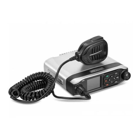
Thales Liberty PRC7332 User manual

LIBERTY
TM
LAND MOBILE RADIO
PRC7332
USER’S GUIDE
APRIL 2009

FRONT MATTER
2 Doc No. 84382 Rev 2
THALES COMMUNICATIONS, INC. PROPRIETARY INFORMATION
!NOTE
LIBERTYTM RADIOS
Please use the following field support contact information:
Contact Info:
Bob DiDonato,
Thales Communications, Inc.
Mobile: 1-410-908-7678
Email: Bob.DiDonato@thalescomminc.com
Scott Glazer,
Thales Communications, Inc.
Mobile: 1-240-422-2612
Email: Scott.Glazer@thalescomminc.com

FRONT MATTER
Doc No. 84382 Rev 2
THALES COMMUNICATIONS, INC. PROPRIETARY INFORMATION iii
COPYRIGHT: APRIL 2009
THALES COMMUNICATIONS, INC.
PUBLISHED AND CONFIDENTIAL WORK
ALL RIGHTS RESERVED
CONFIGURATION NOTICE: This document contains technical information pertinent to the
LibertyTM Radio. The information contained herein is for the support of the LibertyTM Radio.
PROPRIETARY NOTICE: This document contains information proprietary to THALES
COMMUNICATIONS, INC. It is furnished for operation and support purposes only and not for
reprocurement. All reprocurement and manufacturing rights are expressly reserved by THALES
COMMUNICATIONS, INC., and no such use may be made of this document, either directly or
indirectly without the prior written consent of THALES COMMUNICATIONS, INC.
LICENSE AGREEMENTS
This software is licensed solely for use within this product. US Patent Nos. #6,912,495 B2,
#6,199,037 B1, #5,870,405, #5,826,222, #5,754,974, #5,715,365, #5,701,390, #5,649,050,
#5,630,050, #5,630,011, #5,581,656, #5,517,511, #5,491, 772, #5,247,579, #5,226,084, and
#5,195,166.
The AMBE ® voice compression software included in the product is protected by intellectual
property rights including patent rights, copyrights, and trade secrets of Digital Voice Systems,
Inc. The user of this software is explicitly prohibited from attempting to decompile, reverse
engineer, or disassemble the object code, or in any other way convert the object code into a
human-readable form.
! NOTE
This manual contains information that is current as of the
date shown below. Additional functionality is being
developed for the radio and the appearance of operating
screens is subject to change from those shown herein.
Thales Part 84382 Rev 2
April 2009

FRONT MATTER
iv Doc No. 84382 Rev 2
THALES COMMUNICATIONS, INC. PROPRIETARY INFORMATION
RECORD OF CHANGES
Revision Date Description of Change Author
Rev 1 Jan 2009 Initial Pilot Field Trials Version SJA
Rev 2 April 2009 Updated to include scan functions, use of pre-
programmable side buttons, and added FCC information. SJA

FRONT MATTER
Doc No. 84382 Rev 2
THALES COMMUNICATIONS, INC. PROPRIETARY INFORMATION v
TABLE OF CONTENTS
CHAPTER .......................................................................................................................................... PAGE
LICENSE AGREEMENTS .....................................................................................................................................III
LIST OF FIGURES.................................................................................................................................................VII
LIST OF TABLES.................................................................................................................................................VIII
RADIO FREQUENCY ENERGY SAFETY INFORMATION ...........................................................................IX
ELECTROMAGNETIC INTERFERENCE COMPATIBILITY..........................................................................X
SAFETY SUMMARY..............................................................................................................................................XI
NOTATIONS USED IN THIS MANUAL.............................................................................................................XII
FOREWORD.........................................................................................................................................................XIII
CHAPTER 1 GETTING TO KNOW THE RADIO........................................................................................ 1-1
GENERAL INFORMATION........................................................................................................................................ 1-1
EQUIPMENT CHARACTERISTICS............................................................................................................................. 1-2
TECHNICAL CHARACTERISTICS ............................................................................................................................. 1-3
LIBERTYTM RADIO –LOCATION OF CONTROLS AND INDICATORS.......................................................................... 1-4
CONTROLS AND INDICATORS ............................................................................................................................... 1-7
CONTROLS............................................................................................................................................................. 1-7
Special “Hot Keys”.......................................................................................................................................... 1-8
Four-Way Navigation Buttons with Enter Button............................................................................................ 1-9
Side-Buttons................................................................................................................................................... 1-10
INDICATORS......................................................................................................................................................... 1-11
LCD and Keypad Backlight........................................................................................................................... 1-11
LED Indicators............................................................................................................................................... 1-11
Connectors ..................................................................................................................................................... 1-12
CHAPTER 2 DISPLAY / MENU SCREENS .................................................................................................. 2-1
GENERALINFORMATION.................................................................................................................................. 2-1
DISPLAY/MENU SCREENS ................................................................................................................................ 2-2
SPLASH Screen............................................................................................................................................... 2-2
HOME Screen.................................................................................................................................................. 2-3
MENU Screen Displays................................................................................................................................... 2-6
SELECT Menu Screen..................................................................................................................................... 2-7
VIEW Menu Screen......................................................................................................................................... 2-8
PROGRAM Menu Screen................................................................................................................................ 2-9
RADIO INFORMATION Menu Screen........................................................................................................ 2-18
MAINTENANCE Menu Screen .................................................................................................................... 2-19
CHAPTER 3 OPERATING INSTRUCTIONS............................................................................................... 3-1
GENERAL INFORMATION........................................................................................................................................ 3-1
OPERATING INSTRUCTIONS.............................................................................................................................. 3-1
Connecting the Battery..................................................................................................................................... 3-1
Connecting the Antenna................................................................................................................................... 3-1
Radio Programming......................................................................................................................................... 3-1
Turning on the Radio ....................................................................................................................................... 3-2
Menu Access.................................................................................................................................................... 3-3
Transmitting..................................................................................................................................................... 3-4

FRONT MATTER
vi Doc No. 84382 Rev 2
THALES COMMUNICATIONS, INC. PROPRIETARY INFORMATION
Receiving ......................................................................................................................................................... 3-4
P25 Unit to Unit Call ....................................................................................................................................... 3-5
Scanning – Conventional and Priority ............................................................................................................. 3-6
Using the Pre-Programmed Side Buttons......................................................................................................... 3-8
Modifying Menu Selections – SELECT Menu or PROGRAM Menu............................................................. 3-9
Changing ZONES ............................................................................................................................................ 3-9
Screensaver .................................................................................................................................................... 3-10
CHAPTER 4 MAINTENANCE........................................................................................................................ 4-1
GENERAL INFORMATION ........................................................................................................................................ 4-1
OPERATIONAL CHECKOUT..................................................................................................................................... 4-2
RADIO PREVENTIVE MAINTENANCE...................................................................................................................... 4-2
Inspection and Cleaning................................................................................................................................... 4-2
EXTERNAL BATTERY PREVENTIVE MAINTENANCE ............................................................................................... 4-2
TROUBLESHOOTING............................................................................................................................................... 4-3
REMOVAL/REPLACEMENT PROCEDURES -OPERATOR ........................................................................................... 4-4
Audio Accessory Removal/Replacement ........................................................................................................ 4-4
Antenna Removal/Replacement....................................................................................................................... 4-4
Battery Removal/Replacement......................................................................................................................... 4-5
RADIO DISASSEMBLY ............................................................................................................................................ 4-5
CHAPTER 5 BATTERY CHARGERS............................................................................................................ 5-1
GENERAL INFORMATION .................................................................................................................................. 5-1
PHYSICAL CHARACTERISTICS................................................................................................................................ 5-2
Weight and Dimensions ................................................................................................................................... 5-2
Temperature..................................................................................................................................................... 5-2
ELECTRICAL CHARACTERISTICS............................................................................................................................ 5-2
PERFORMANCE ...................................................................................................................................................... 5-2
OPERATING INDICATIONS ...................................................................................................................................... 5-3
CHAPTER 6 ACCESSORIES AND ANCILLARY EQUIPMENT .............................................................. 6-1
GENERAL............................................................................................................................................................... 6-1
AVAILABLE ACCESSORIES AND ANCILLARYEQUIPMENT FOR THE LIBERTYTM RADIO ...................................... 6-1
Antennas .......................................................................................................................................................... 6-1
Batteries ........................................................................................................................................................... 6-2
Battery Chargers .............................................................................................................................................. 6-2
Cases / Holsters................................................................................................................................................ 6-3
Audio Accessories............................................................................................................................................ 6-3
Cables............................................................................................................................................................... 6-4
Surveillance Equipment ................................................................................................................................... 6-4
CHAPTER 7 GLOSSARY................................................................................................................................. 7-1
ACRONYMS’ ...................................................................................................................................................... 7-1
DEFINITIONS.......................................................................................................................................................... 7-2
APPENDIX A – QUICK REFERENCE GUIDE.................................................................................................. 7-1
INDEX..........................................................................................................................................................INDEX - 1

FRONT MATTER
Doc No. 84382 Rev 2
THALES COMMUNICATIONS, INC. PROPRIETARY INFORMATION vii
LIST OF FIGURES
FIGURE 1-1 LIBERTYTM RADIO ................................................................................................................................... 1-0
FIGURE 1-1 LIBERTYTM RADIO PHYSICAL CHARACTERISTICS .................................................................................... 1-4
FIGURE 1-2 KEYPAD................................................................................................................................................... 1-7
FIGURE 1-3 LIBERTY SPECIAL “HOT KEYS”............................................................................................................... 1-8
FIGURE 1-4 FOUR-WAY NAVIGATION BUTTONS WITH ENTER BUTTON ..................................................................... 1-9
FIGURE 1-5 PROGRAMMABLE SIDE BUTTONS........................................................................................................... 1-10
FIGURE 1-6 LOCATION OF LED................................................................................................................................ 1-11
FIGURE 1-7 SIDE CONNECTOR.................................................................................................................................. 1-12
FIGURE 1-8 ANTENNA CONNECTOR.......................................................................................................................... 1-13
FIGURE 1-9 BATTERY CONNECTOR .......................................................................................................................... 1-14
FIGURE 2-1 LIBERTYTM HOME SCREEN DISPLAY (SAMPLE)....................................................................................... 2-2
FIGURE 2-2 DEFAULT “SPLASH”SCREEN ................................................................................................................... 2-2
FIGURE 2-3 LIBERTYTM HOME SCREEN DISPLAY (SAMPLE)....................................................................................... 2-3
FIGURE 2-4 OPERATING SCREEN –“HOME”SAMPLE SCREEN.................................................................................... 2-4
FIGURE 2-5 OPERATING SCREEN –SOFTKEYS MENU ................................................................................................. 2-5
FIGURE 2-6 SELECT MENU SCREEN ......................................................................................................................... 2-7
FIGURE 2-7 VIEW MENU SCREEN.............................................................................................................................. 2-8
FIGURE 2-8 PROGRAM MENU SCREEN –P25 CHANNEL TYPE................................................................................. 2-9
FIGURE 2-9 PROGRAM MENU SCREEN –ANALOG NARROWBAND (AN) ............................................................... 2-12
FIGURE 2-10 PROGRAM MENU SCREEN –ANALOG WIDEBAND (AW) ................................................................. 2-14
FIGURE 2-11 RADIO INFORMATION MENU SCREEN........................................................................................... 2-18
FIGURE 2-12 MAINTENANCE MENU SCREEN....................................................................................................... 2-19
FIGURE 3-1 RADIO ON/OFF/VOLUME KNOB AND ZONE SELECT ............................................................................. 3-2
FIGURE 3-2 MENU ACCESS......................................................................................................................................... 3-3
FIGURE 3-3 RADIO ON/OFF/VOLUME KNOB............................................................................................................. 3-4
FIGURE 3-4 P25 UNIT TO UNIT CALL ......................................................................................................................... 3-5
FIGURE 4-1 MAINTENANCE MENU SCREEN............................................................................................................... 4-1

FRONT MATTER
viii Doc No. 84382 Rev 2
THALES COMMUNICATIONS, INC. PROPRIETARY INFORMATION
LIST OF TABLES
TABLE 1- 1EQUIPMENT CHARACTERISTICS............................................................................................................... 1-2
TABLE 1- 2TECHNICAL CHARACTERISTICS ............................................................................................................... 1-3
TABLE 1-3 PHYSICAL DESCRIPTION ........................................................................................................................... 1-5
TABLE 1-4 KEYPAD CHARACTERS.............................................................................................................................. 1-8
TABLE 1-5 LED INDICATORS ................................................................................................................................... 1-11
TABLE 2-1 STATUS AREA SYMBOLS........................................................................................................................... 2-3
TABLE 2-2 CONTEXT AREA DESCRIPTIONS ................................................................................................................ 2-4
TABLE 2-3 SOFTKEY MENU OPTIONS ......................................................................................................................... 2-6
TABLE 2-4 FUNCTIONAL CATEGORY OPTIONS ........................................................................................................... 2-6
TABLE 2-5 SELECT MENU OPTIONS ......................................................................................................................... 2-7
TABLE 2-6 VIEW CHANNEL PARAMETERS.................................................................................................................. 2-8
TABLE 2-7 PROGRAM MENU –P25 CHANNEL TYPE ............................................................................................. 2-10
TABLE 2-8 PROGRAM MENU –ANALOG NARROWBAND (AN).............................................................................. 2-12
TABLE 2-9 PROGRAM MENU –ANALOG WIDEBAND (AW) .................................................................................. 2-15
TABLE 2-10 CTCSS TONES AND CODES.................................................................................................................. 2-17
TABLE 2-11 CDCSS CODES ..................................................................................................................................... 2-17
TABLE 2-12 MAINTENANCE MENU OPTIONS....................................................................................................... 2-20
TABLE 3-1 SCAN AND PRIORITY SCAN SIDE BUTTON OPTIONS.................................................................................. 3-7
TABLE 4-1 OPERATOR TROUBLESHOOTING GUIDE.................................................................................................... 4-3
FIGURE 5-1 LIBERTYTM SINGLE-BAY CHARGER......................................................................................................... 5-1
TABLE 5-2 BATTERY CHARGER WEIGHTS AND DIMENSIONS ..................................................................................... 5-2
TABLE 5-3 CHARGING AND STORAGE TEMPERATURES .............................................................................................. 5-2
TABLE 5-4 CHARGING AND STORAGE TEMPERATURES .............................................................................................. 5-2
TABLE 5-5 CHARGER PERFORMANCE......................................................................................................................... 5-2
TABLE 5-6 SINGLE-BAY CHARGE STATUS INDICATORS ............................................................................................. 5-3
TABLE 6-1 ANTENNA VERSIONS................................................................................................................................ 6-1
TABLE 6-2 LIBERTYTM BATTERIES ............................................................................................................................ 6-2
TABLE 6-3 LIBERTYTM BATTERY CHARGERS............................................................................................................. 6-2
TABLE 6-4 LIBERTYTM CASES /HOLSTERS ................................................................................................................ 6-3
TABLE 6-5 LIBERTYTM AUDIO ACCESSORIES............................................................................................................. 6-3
TABLE 6-6 LIBERTYTM CABLES ................................................................................................................................. 6-4
TABLE 6-7 LIBERTYTM SURVEILLANCE EQUIPMENT.................................................................................................. 6-4

FRONT MATTER
Doc No. 84382 Rev 2
THALES COMMUNICATIONS, INC. PROPRIETARY INFORMATION ix
RADIO FREQUENCY ENERGY SAFETY INFORMATION
This THALES transceiver has been evaluated and complies with the standards listed below, in regards to
Radio Frequency (RF) energy and electromagnetic energy (EME) generated by the transceiver.
•FCC RF exposure limits for Occupational Use Only. RF Exposure limits adopted by the FCC are
generally based on recommendations from the National Council on Radiation Protection and
Measurements, & the American National Standards Institute.
•FCC OET Bulletin 65 Edition 97-01 Supplement C
•American National Standards Institute (C95.1 . 1992)
•American National Standards Institute (C95.3 . 1992)
WARNING:
This THALES tr
ansceiver generates RF EME while transmitting. RF EME
(Radio Frequency Electric & Magnetic Energy) has the po
tential to cause
slight thermal
or heating effects to any part of your body less than the
recommended distance from this radio transmitter’s antenn
a. RF energy
exposure is determined primarily by the distance to and the power of the
transmitting device. In general, RF exposure is minimized when the lowest
possible power is used or transmission time is kept to the minimum required
for consistent commu
nications, and the greatest distance possible from the
antenna to the body is maintained. The transceiver has been designed for and is
classified for Occupational Use Only. Occupational/ controlled exposure limits
are applicable to situations in which persons are exposed to RF energy as a
consequence of their employment, and such persons have been made aware of
the potential for exposure and can exercise control over their exposure. This
means you can use the transceiver only if you are aware of the potential
hazards of operating a transceiver and are familiar in ways to minimize these
hazards. This transceiver is not intended for use by the general public in
uncontrolled environments. Uncontrolled environment exposure limits are
applicable to situations in
which the general public may be exposed to RF
energy, or in which the persons who are exposed as a consequence of their
employment may not be fully aware of the potential for exposure or cannot
exercise control over their exposure.
The following list provides you with the information required to ensure that you are aware of RF
exposure and of how to operate this transceiver so that the FCC RF exposure limitations are not exceeded.
•Do not transmit for more than 50% of the total transceiver use time; transmitting over 50% of the
total use time may exceed the limits in accordance to the FCC RF exposure requirements.
Nominal transceiver operation is 10% transmission time, 10% reception time, and 80% stand-by
time.
•Use only the specified antenna for this transceiver; this may be either the antenna provided with
the transceiver or another antenna authorized by THALES.
CAUTION
To ensure that your exposure to RF EME is within the FCC limits for
occupational use, you must observe and adhere to the above points.

FRONT MATTER
x Doc No. 84382 Rev 2
THALES COMMUNICATIONS, INC. PROPRIETARY INFORMATION
RF EXPOSURE GUIDELINES
To ensure that exposure to RF electromagnetic energy is within the FCC allowable limits
for occupational use, always adhere to the following guidelines:
•DO NOT operate the radio without a proper antenna attached, as this may damage
the radio and may cause the FCC RF exposure to be exceeded. A proper antenna
is the antenna supplied with the radio or an antenna specifically authorized by
Thales Communications Inc. (Refer to Table 6-1, Antenna Versions)
•ALWAYS use Thales authorized accessories (antenna, batteries, speaker/mic,
etc…). When worn on the body, always place the radio in a Thales recommended
clip or holster meant for this product. The use of other than recommended or
approved body-worn accessories may result in RF exposure levels which exceed
the FCC Occupational/Controlled environment RF exposure limits. (Refer to
Chapter 6 for a complete listing of Available Accessories and Ancillary
Equipment authorized for use on the LibertyTM Radio.
•ALWAYS keep the radio and its antenna away from the body and face when
transmitting to ensure FCC RF exposure compliance requirements are not
exceeded:
Face with NO Accessory
Radio: 2.5 cm
Antenna: 5.5 cm
Body worn using belt clip
Radio: 1.6 cm
Antenna: 2.0 cm
Body worn using belt holster
Radio 2.0 cm
Antenna: 2.2 cm
ELECTROMAGNETIC INTERFERENCE COMPATIBILITY
Electronic devices are susceptible to electromagnetic interference (EMI) if they are not adequately
shielded or designed for electromagnetic compatibility. Because this transceiver generates RF energy,
it can cause interference to such equipment.
•Turn OFF your transceiver where signs are posted to do so. Hospitals and health care facilities
use equipment that is sensitive to electromagnetic radiation.
•Turn OFF your transceiver while on board an aircraft when so instructed. Use of the transceiver
must be in accordance with airline regulations and/or crew instructions.
“OCCUPATIONAL USE ONLY” RADIO
The LibertyTM Radio generates RF electromagnetic energy during transmit mode of
operation. This radio is designed and classified for “Occupational Use Only”, meaning it
must be used only during the course of employment by individuals aware of the hazards
and the ways to minimize such hazards. This radio is NOT intended for use by the
General Population in an uncontrolled environment.
LIBERTYTM RADIO COMPLIANCE WITH FCC PART 15 RULES
This device complies with Part 15 of the FCC Rules. Operation is subject to condition that
this device does not harmful interference.

FRONT MATTER
Doc No. 84382 Rev 2
THALES COMMUNICATIONS, INC. PROPRIETARY INFORMATION xi
SAFETY SUMMARY
The following are general safety precautions that are not related to any specific procedure,
and do not appear elsewhere in this manual. These Safety Summaries are recommended
precautions that all personnel must understand and apply during any given phase of
operation and maintenance. Each chapter has other specific warnings and cautions.
KEEP AWAY FROM LIVE CIRCUITS
Personnel must at all times observe all safety regulations. Do not replace components or
make adjustments inside equipment with power turned on. Under certain conditions,
dangerous voltages may exist when the power switch is in the off position due to charges
retained by capacitors. To avoid injury, always remove power and discharge and ground a
circuit before touching it.
VOLTAGES WITHIN THIS EQUIPMENT ARE HIGH ENOUGH TO
ENDANGER LIFE.
(Applies to battery chargers only)
Covers are not to be removed except by persons qualified and authorized to do so and
these persons should always take extreme care once the covers have been removed.
HAZARDS OF ELECTROMAGNETIC RADIATION TO ORDNANCE (HERO)
DO NOT operate the radio within 27 feet (8 meters) of any type of fuzed ordnance.
Operating the radio in close proximity to ordnance MAY induce or otherwise couple
currents and/or voltages of magnitudes large enough to initiate electro-explosive devices
or other sensitive explosive components of weapon systems, ordnance, or explosive
devices.
CAUTION - LITHIUM ION BATTERIES
Li-ion batteries have a very high energy density. Exercise precaution when handling and
testing. Do not short circuit, overcharge, crush, mutilate, nail penetrate, apply reverse
polarity, expose to high temperature or disassemble. High case temperature resulting from
abuse could cause physical injury.
REPAIRS, ALTERATIONS TO EQUIPMENT
Repairs to this equipment should be made only by an authorized technician or facility
designated by Thales. Any repairs, alterations, or substitutions of recommended parts
made by the user to this equipment not approved by the manufacturer could void the user’s
authority to operate the equipment in addition to Thales’s Warranty.

FRONT MATTER
xii Doc No. 84382 Rev 2
THALES COMMUNICATIONS, INC. PROPRIETARY INFORMATION
NOTATIONS USED IN THIS MANUAL
Throughout this manual, there are WARNING, CAUTION, or NOTE Statements that emphasize safety
hazards, or care that should be observed.
WARNING:
A WARNING Statement is an operation procedure,
practice, or other condition that might result in injury or
death if not carefully observed. Do not proceed beyond a
WARNING symbol until the conditions identified are fully
understood or met.
CAUTION
A CAUTION Statement indicates an operational procedure,
practice or other condition, which, if not performed
correctly or adhered to, could result in a risk of danger,
damage to the equipment, or severely degrade equipment
performance.
!NOTE
A NOTE Statement that calls attention to supplemental
information that may improve system performance or
clarify a process or procedure.

FRONT MATTER
Doc No. 84382 Rev 2
THALES COMMUNICATIONS, INC. PROPRIETARY INFORMATION xiii
FOREWORD
!NOTE
The radio operation (man-machine interface) shown in this
manual reflect Radio Software Version 70 and PC
Programmer Version 00.00.01.14. Some screens do not
correspond to those in earlier radio software or PC
Programmer versions.
The organization of the LibertyTM User’s Guide is as follows:
a. Chapter 1 Getting to Know the Radio. This chapter provides general information for the
LibertyTM Radio including equipment description and purpose.
b. Chapter 2 Display / Menu Screens – This chapter covers information covering the various
displays / menu screens that can be found on the radio.
c. Chapter 3 Operating Instructions – This chapter describes the operating instructions for the
radio.
d. Chapter 4 Maintenance - This chapter provides instructions required for on-equipment and off-
equipment preventive and corrective maintenance of the LibertyTM Radio.
e. Chapter 5 Battery Chargers – This chapter provides a brief overview on the operation of the
chargers .
f. Chapter 6 Accessories / Ancillaries – This chapter provides a complete listing of accessories and
ancillaries used with the LibertyTM Radio.
g. Chapter 7 Glossary - The glossary provides a definition of the special terms and acronyms used
in this document.
h. Index
i. Attachments –
Quick Reference Guide (QRG)

GETTING TO KNOW THE RADIO
1-0 Doc No. 84382 Rev 2
THALES COMMUNICATIONS, INC. PROPRIETARY INFORMATION
Figure 1-1 LibertyTM Radio

GETTING TO KNOW THE RADIO
Doc No. 84382 Rev 2
THALES COMMUNICATIONS, INC. PROPRIETARY INFORMATION 1-1
CHAPTER 1 GETTING TO KNOW THE RADIO
Description Page Number
General Information 1-1
Equipment Characteristics 1-2
Technical Characteristics 1-3
LibertyTM Radio – Location of Controls and Indicators 1-4
Controls and Indicators 1-7
Controls 1-7
Special “Hot Keys” 1-8
Four Way Navigation Buttons with ENT Button 1-9
Indicators 1-10
LCD and Keypad Backlight 1-11
LED Indicators 1-11
Connectors 1-12
GENERAL INFORMATION
The LibertyTM Multi-Band Radio is a portable, hand-held, battery operated transceiver capable of
providing both secure and non-secure communications.
The radio is software upgradeable in the field, and selected features are capable of being enabled and
disabled on a per radio basis. In addition, multiple software loads will be available with encryption
support added or removed.
The LibertyTM Multi-Band radio is designed to provide Public Safety communications, both voice and
data, in the following frequency bands
•VHF (136-174 MHz),
•UHF (380-520 MHz),
•700 MHz (763-775/793-805 MHz), and
•800 MHz (806/851-824/869 MHz)
The LibertyTM Radio is designed to be extremely easy-to-use and programmable intuitively via either
Keypad or PC.
The LibertyTM Radio consists of the following items:
•LibertyTM Multi-band portable radio
•Multi-band Antenna
•Lithium-Ion Battery

GETTING TO KNOW THE RADIO
1-2 Doc No. 84382 Rev 2
THALES COMMUNICATIONS, INC. PROPRIETARY INFORMATION
•Standard Battery Charger
•Belt Clip
EQUIPMENT CHARACTERISTICS
Table 1- 1 Equipment Characteristics
Characteristics Specification
Modes of Operation •Analog 12.5/25 kHz
•P25 Digital (12.5 kHz), Conventional
•P25 Trunking (Future)
Channel Spacing •12.5 / 25 kHz channels
•2.5 / 3.125 kHz Frequency Increments
Frequency Stability •1.5 ppm (-30°C (22°F ) to + 60°C (140°F))
Interoperability •Legacy Analog FM Radios
•P25 Digital Radios
•P25 Trunking Systems (Future)
Programmable Channels
Initial Release •1 banks (Groups of Zones)
•16 Zones (up to 256 Channels)
•User Programmable from
oFront Panel Menu
o
PC Programmer
Production Release •Up to 2608 Conventional Channels or Trunked Talkgroups
(Any Combinations)
•10 banks (Groups of Zones)
•175 Zones (up to 16 channels / talkgroups each)
•3 additional event zones with up to 16 channels / talkgroups
each)
•User Programmable from
oFront Panel Menu
oPC Programmer
oRadio to Radio Cloning
•Clear / Encrypted Selection on a Channel-by-Channel or
Talkgroup Base
•Password Protected to Limit Access

GETTING TO KNOW THE RADIO
Doc No. 84382 Rev 2
THALES COMMUNICATIONS, INC. PROPRIETARY INFORMATION 1-3
TECHNICAL CHARACTERISTICS
Table 1- 2 Technical Characteristics
Characteristics Specification
Weight LibertyTM Radio including battery ~28 ounces (794 grams)
Dimension 2.5” W x 1.9” D x 7” L (excluding antenna and knobs)
6.4cm W x 4.8cm D x 17.8 cm L (excluding antenna and knobs)
Operating Temperature (-30°C* (22°F ) to + 60°C (140°F))
(*cold starts below -25°C may require a 3 minute warm-up for
full specification compliance)
Storage Temperature Low Temperature – minimum of -40°C (-40°F) for 24 hours
High Temperature -- maximum of 85°C (+85°F) for 24 hours
Operational Low Pressure 15,000 feet operational
Storage Low Pressure Exposure to storage at 30,000 ft.
Charging Temperature 0°C (32°F) to + 45°C (113°F)
Rechargeable Battery Operating
Temperature Range -20°C (-4°F) to + 60°C (140°F)
Rated Power UHF – 5W
VHF – 5W
700 MHz – 2.5W
800 MHz – 3.0W

GETTING TO KNOW THE RADIO
2-4 Doc No. 84403 Rev 2
THALES COMMUNICATIONS, INC PROPRIETARY INFORMATION
LIBERTYTM RADIO – LOCATION OF CONTROLS AND INDICATORS
The LibertyTM Radio Physical Features are as shown in the figure below.
Figure 2-1 LibertyTM Radio Physical Characteristics

GETTING TO KNOW THE RADIO
Doc No. 84382 Rev 2
THALES COMMUNICATIONS, INC. PROPRIETARY INFORMATION 1-5
Table 1-3 Physical Description
Item
No. Description Programmed
by PC
Programmer
1 Channel Switch – This switch can be programmed to select any 16 settings,
(not all positions need be programmed).
2 2-Position Programmable Switch – Although often referred to as the
“Encryption Switch”, this switch is actually a programmable switch. This
switch can be programmed to select any two settings. There is no “typical”
setting for this switch.
Current Version -- EXT/INT Audio (“ ” EXT and “0” INT)
3 Antenna connector – Antenna connects to the radio here for TX and RX of
RF signals.
4 Status LED – Used to visually indicate various states of the radio. May be
solid RED, GREEN, or YELLOW-ORANGE, or flashing individual
colors or combinations of colors, depending on the radio state.
5 Speaker – radio internal speaker
6 Programmable Soft-key Button 1 – This button activates the feature or
function displayed immediately above it on the color display. Additional
entries are accessed by scrolling through the selections using the left/right
navigation buttons. The features on the display can be programmed to
select any programmable function of the radio.
7 Programmable Soft-key Button 3 – This button activates the feature or
function displayed immediately above it on the color display. Additional
entries are accessed by scrolling through the selections using the left/right
navigation buttons. The features on the display can be programmed to
select any programmable function of the radio.
8 Programmable Soft-key Button 2 – This button activates the feature or
function displayed immediately above it on the color display. Additional
entries are accessed by scrolling through the selections using the left/right
navigation buttons. The features on the display can be programmed to
select any programmable function of the radio.
Current Version – Locked to PRIV Call on P25
9 Keypad – Used to enter alpha-numeric and symbols similar to a cell phone.
10 4-Way Navigation Buttons with Enter – UP/DOWN/LEFT/RIGHT/ENTER
buttons used to navigate around the Color Display and highlight displayed
icons or fields. The ENTER button is used to “enter” the feature
highlighted, which may be a menu, a programming option, or other function
as programmed into the radio.
11 Microphone – radio internal microphone
12 Color Display – Color LCD for the display of radio status and other
information.

GETTING TO KNOW THE RADIO
1-6 Doc No. 84382 Rev 2
THALES COMMUNICATIONS, INC. PROPRIETARY INFORMATION
Item
No. Description Programmed
by PC
Programmer
13 3-Position Programmable Switch – This switch can be programmed to
select any three settings. Typically, this switch is programmed for 3-
different Zones/Groups.
Current Version – Locked to Zones 1, 2, and 3.
14 ON/OFF/Volume Control Knob – Used to turn the radio ON & OFF, and to
control the volume level for the internal speaker when the radio is on. The
most counter-clockwise position, (first position), is radio OFF; the next
clockwise position, (second position), is radio ON with the internal speaker
muted; the next 14 clockwise positions, (positions 3 through 16), are radio
ON while sequencing through the lowest to highest volume settings on the
internal speaker.
15 Side Button 1 – This button can be programmed to select any feature.
Current programmable functions are : Disabled, Ni/Low Power, Monitor,
Scan, Priority Scan, and Talkaround.
16 Side Button 2 – This button can be programmed to select any feature
Current programmable functions are : Disabled, Ni/Low Power, Monitor,
Scan, Priority Scan, and Talkaround.
17 Side Button 3 – this button can be programmed to select any feature.
Current programmable functions are : Disabled, Ni/Low Power, Monitor,
Scan, Priority Scan, and Talkaround.
18 PTT (Push-to-Talk) Button – Press and Hold button used to initiate a call,
i.e., transmit on a channel.
19 Battery – Provides DC power to the radio.
20 Emergency Button – Although commonly referred to as the “Emergency
Button”, this PRESS & Hold button is actually a programmable button.
This button can be programmed to cause the radio to enter any radio
feature/state. Typically, this button is programmed to cause the radio to
enter into an “Emergency” mode of operation.
21 Side Connector – Used to connect to accessories and devices, PC
Programmer (i.e., PC), KFD, etc.
Note: A “” indicates that this function is programmable via the PcProgrammer.
Table of contents
Other Thales Radio manuals


