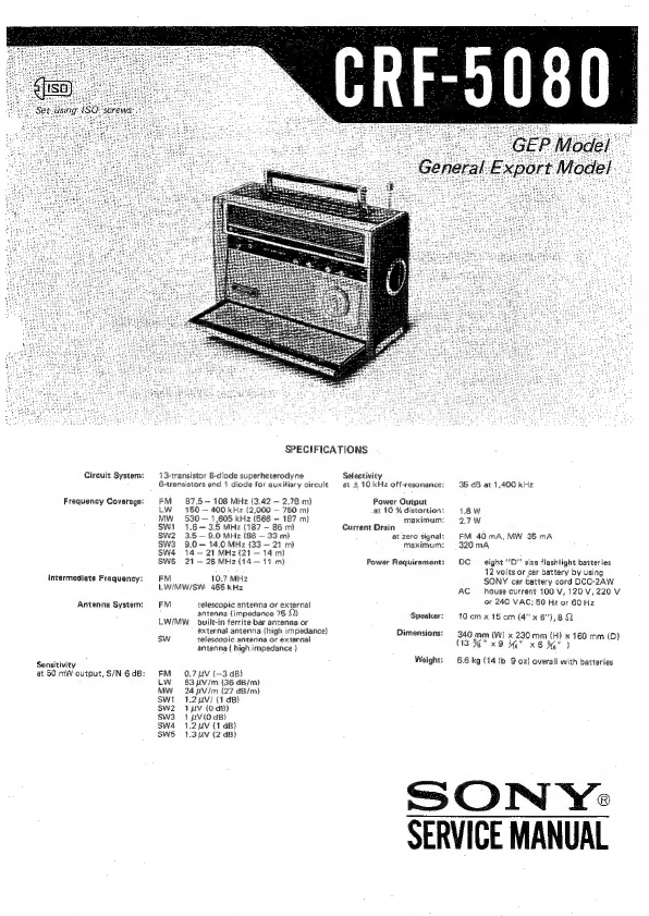
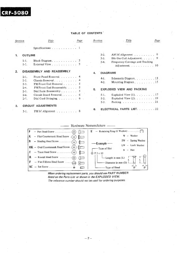
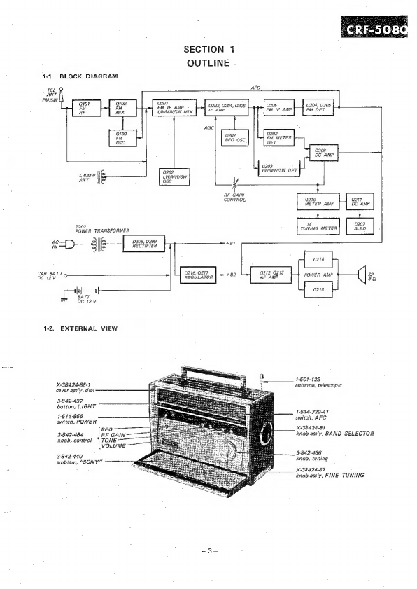
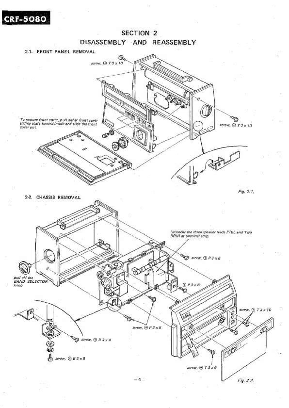
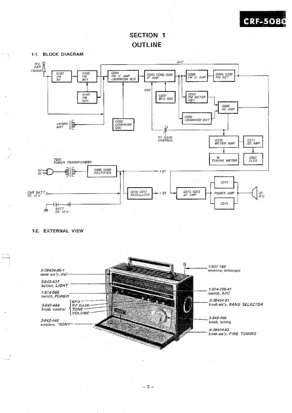
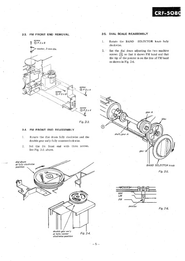
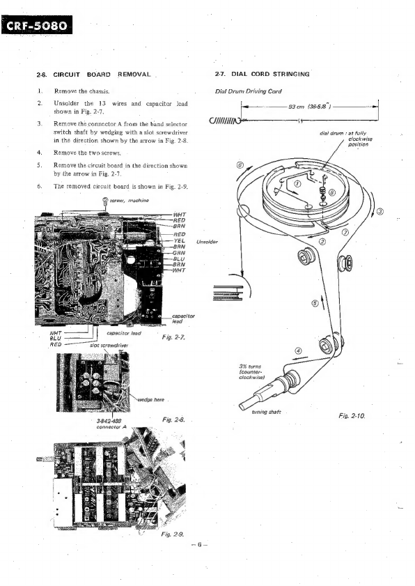
Sony CRF-5080 User manual
Other Sony Radio manuals

Sony
Sony ICF-M760L User manual

Sony
Sony SRF-X90 Owner's manual

Sony
Sony ICF-19 User manual

Sony
Sony Walkman SRF-M97 User manual

Sony
Sony Walkman SRF-M35 User manual

Sony
Sony ICF-703 User manual

Sony
Sony ICF-F1 User manual

Sony
Sony TR-714 User manual

Sony
Sony CFS-B75 User manual

Sony
Sony SRF-PSY03 User manual

Sony
Sony S2 Sports Walkman SRF-M80V User manual

Sony
Sony XDR-S10HDIP User manual

Sony
Sony Walkman SRF-H3 User manual

Sony
Sony ICF-SW12 User manual

Sony
Sony CFS-715S User manual

Sony
Sony XDR-S3HD - HD / AM User manual

Sony
Sony ICF-P36 User manual

Sony
Sony ICF-M1000 User manual

Sony
Sony SRF-T615 User manual

Sony
Sony SRF-M806 User manual