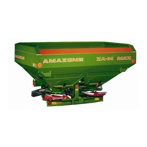
Amazone JET 1203 User manual

I
I
I
I
I
I
I
I
I
I
I
I
I
I
DB 486 (GB) 6.88
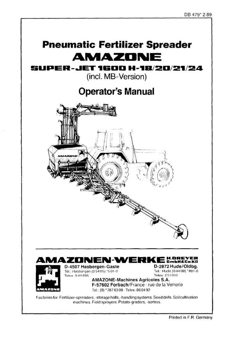
Pneumatic
Fertilizer
Spreader
AMAZDNE
JET
'12D3/'15D3
H
Instruction
Manual
To ensure that you
will
get the best possible results from
your
"AMAZONE"
we
would
ask you to read and observe these
instructions
carefully. You
will
of
course
appreciate
that
we
will
not
be able to
accept
claims
under
guarantee if any damage is caused due to
incorrect
operation.
AMIAZDNEN-WERKE
t'.:!:.':~~~-=
D-4507 Hasbergen-Gaste D-2872 Hude/Oldbg.
Tel.
: Hasbergen (05405) *501-0
Tel.
: Hude (04408) *801-0
Telex: 9
44
895 Telex: 2
51
010
AMAZONE-Machines Agricoles S.A.
F-57602 Forbach/France · rue de la Verrerie
Tel.
:
(8)
*7876308 ·Telex:
860492
Factoriesfor: Fertilizer-spreaders, -storage halls, -handling systems. Seeddrills.Soil cultivation
machines.Field sprayers. Potato-graders,-sorters.
Printed
in
F.
R.
Germany

P
le
ase enter the serial number of your pneumatic broadcaster
here.
You
will find the number stamped
on
the right front side of
the main frame.
Please always quote the serial number when ordering spareparts
or making enquiries.
Machine serial no.
I
I
I
I
I
I
I
I
I
I
I
I
I

I
I
I
I
I
I
I
I
I
I
I
I
I
I
Contents
1
1
.1
1.2
1.3
1.4
1.5
1.6
2
2.1
3
3.1
3.2
3.3
3.4
3.5
3.6
3.7
I 3.8
3.9
3.10
4
4.1
4.2
4.3
4.4
4.5
4.6
4.7
4.8
4.9
5
5.1
5.2
5.3
5.4
5.5
5.6
5.7
5.8
5.9
5.10
5.11
5.12
6
6.1
6.2
6.3
7
7.1
7.2
7.3
Specification of the machine
.....
.
.....
...............
...
..........
. . .
Manufactur
er
....
..
........
...........
...
......
.
........
.
....
...
....
.
Type
of
pneumatic
spreaders
..............................
. . .
..
.
......
.
Boom
sizes
......
.
...............
......
.
..............
. . .
..
........
.
Techn
ical
data
..................
..
.
..
.
..........
.
...
...
.
.. ..
........
.
Application range.
..
.
.............
......
...
.
.....
....
..
. . .
.....
......
.
Description
of
the mach
in
e's
function
........
...
...........
. . .
..
. . .
......
.
Hint~ ~pon receiving the machine.
....
.
...............
........
..
..
.
..
. .
Receiving
..
.
..
.
..
. . . .
..
....
.
...
. .
..
. .
..
..
...
.
.. ..
.....
.
........
....
.
Putt
in
g into operation .
..
.
..
.......
.
..
. .
..
....
...
.
....
....
..
..
... ...
. .
General notes
...
.....
.........
.
..
...
.
.......
. .
...
.....
...
.
...
.
...
. . .
Attaching to the tractor
...........
. . . . .
..
.
..
...
.
..
...
...
. . .
......
. .
..
. .
Universal joint shaft
....
. .
..
..
..
.....
..
.........
...
. .
..
.....
.
.. ..
.....
.
Hydraulic circuit (principle
of
function)
.....
.
..
..
.
.......
..
.
...
..
.
...
.
..
. . . .
Connecting the hydraulics to the tractor
..
. . .
......
..
.
..
.
.....
..
.
......
...
.
Connecting
of
control box
SK
J (JET)
...
..
...
..
...
.
..
....
. . .
.......
..
....
.
Linking up SKJ 1 with
AMATRON
(special option)
......
. .
...
.
..
. .
.....
...
..
.
Fitting of the
boom
halves
.................
.. ..
.....
...
.....
.
..
.
.......
.
Completing and fitting
of
injector sluice
.....
. .
........
.
....
..
.
..
...
.....
. . .
Installing of the metering units
.....
.
.....
.
..
.
..
.
..............
.
.........
.
Practical operation
in
the field .
................
.
..
. . .
..
.
........
....
. . .
Filling of the
spreader
..
..
......
.
.....
..
. .
........
. .
....
.
..
..
. . . . .
....
.
Setting
of
spread rate
..............
.......
.....
..
....................
.
Calibrating the required spread rate
.................
.
.....
.
...
.
.........
.
Changing spread rate during operation. .
..........
.
.. ..
. . .
....
. . .
...
....
. .
Matching spread rate to tractor
gear
change
....
. .
.......
..
. .
..
.
..........
.
Folding of
booms
........
.
..
.
............
.
.......
.
..................
. . .
Normal spreading and top dressing. .
........
..
......
...
....
..
.
...
.......
.
Spreading on the field
.....
.
......
.
..
.. ..
.
..
.............
. .
...........
.
Hints for special care
..
...
............
.
...
.
..
.
...
..
.
..
.......
.......
..
.
Special optional equipment . . .
..
.
.. ..
. .
..
. .
..
.
..
. .
..
...
.
...
. . . . .
..
.
..
.
Hydraulic half side control
of
metering unit
........
..
.
..
.......
.....
. . .
...
. .
Two-way
valve .
.........
....................
.
.........
.
..
.
.......
. . . .
Hydraulic
boom
lifting
...
..
............
.
..............................
.
Hydraulic
double
control
................
....................
..
..
. . .
...
.
Hydraulic
boom
section spread control .
..
...
.............................
.
Preconditions for fitting hydraulically actuated special options
without using the solenoid control
chest
.
...
......
...............
.
........
.
Preconditions for fitting hydraulically actuated special options
when
using the solenoid control
chest
..
.
.....
.
......
.
..........
.
........
.
Metering unit for grass
seeds
or
for micro granulars
...................
..
..
. . .
Universal joint shaft with free clutch
.....
.
...
.. ..
. . .
..
. .
.....
..
...
. .
.....
.
Foam
marker
....................
..
...
..
.
....
.........
......
. .
...
.
..
.
Position lights, tail lights, light carriers
....................................
.
Row
spreading
attachment
(for 1Om- and 12
m-booms
with
manual
boom
with manual
boom
lifting only)
......
.
.....
....
....
.......
..
. .
Care, maintenance, emtpying and parking of the machine.
....
. .
..
.
...
.
...
.
General hints .
...............................................
...
....
.
Greasing plan
...
.....
.
..
. . .
....
.....
.
............
.
....
........
.....
.
Attention: Hints
for
assembling the blower wheel shaft. .
....
.
..........
.
..
.
..
.
Function trouble/Trouble shooting
......
............
....
..............
.
Electric control box
..
.
....
.
..
.
.......................
.
........
.
......
.
Hydraulics .
....................
.
.....
...
...
.............
.
..
. .
....
..
.
Continuing field operation after break
down
of electrical functions
..............
.
page
4
4
4
4
4
5
5
6
6
6
6
7
9
9
10
13
15
17
17
17
19
19
19
19
25
27
27
29
29
31
32
32
32
32
33
33
35
36
37
37
37
37
37
39
39
39
40
41
41
44
46
3

1 Specification of the machine
1.1
Manufacturer
AMAZONEN-WERKE,
H.
Dreyer GmbH & Co.
KG,
P.
0.
Box 51, D-4507 Hasbergen-Gaste, West Germany
1.2 Type of pneumatic spreaders
AMAZONE JET 1203 H .
AMAZONE JET 1503 H .
1.3 Boom sizes
10 m working width
12 m working width
15 m working width
16 m working width
18 m working width
1.4 Technical data
Length
...
.
Filling height . . .
at working width
number of jets
jet spacing
hydr.boom folding
Transport. width
Total height
Weight of booms
Spreadrate at
8 k.p.h.
in
kg/ha
4
10 m 12 m
16 16
0.625 m 0.75 m
option option
2.50 m 2.50 m
2.36 m 2.82 m
126
kg
140
kg
30-750
30-750
15 m
30
0.50 m
stand.
2.90 m
2.98 m
233
kg
30-930
1,
1!
I
order-No. 1!
. 296
001
I
. 217
001
I
I'
. 18 410
. 18 510 I
. 18 610
. 18 710
. 18 810 I
. 1.34 m I
. 0.90 -1.05 m
16 m 18 m I
32 32
0.50 m 0.56 m I
stand. stand.
2.90 m 2.90 m
2.98 m 3.16 m
238
kg
272
kg
I
30-930
30-930
I
I
I
I

I
I
I
I
I
I
I
I
I
I
I
I
I
I
Type of pneumatic spreader JET 1203 H JET 1503 H
Net weight of base machine
Hopper capacity
Metering system
Checking of spread rate
Adjustable spread fan
Stepless spread rate setting
370
kg
1200 I 399
kg
1500 I
forced speed metering system
(stud wheels)
Possib
ili
ty for calibrating
for normal spread and top dressi
ng
by oil motor and
electrical remote control
We reserve the right for any technical changes without notice.
1.5 Application range
The pneumatic spreaders AMAZONE JET 1203 and JET 1503 are suitable for spread-
ing granular fertilizers, microgranules, seeds
and
material of similar consistancy.
1.6 Description of the machine's function
The material for spreading
is
metered from the hopper into the injector slu
ic
es
by forced
feed toothed wheel rollers, which are driven hydraulic motor.
The p.t.o
.-
driven blower fan provides a stream of air which transports the spreading ma-
terial from the injector sluices through the pipes
to
the distribution jets at the booms.
Deflector plates spread the material fan-like
to
the ground whereby the spreading fans
overlap one another 2 - 4 fold
to
ensure
an
optimum lateral distribution.
5

2 Hints upon receiving the machine
2.1 Receivi
ng
On
recei
pt
check the spreader for damage and missing parts. Claims must be made
to
the carrier immediately if compensation is to
be
obtained. Please ensure also that
al
l
parts
li
sted
in
the consignment note have been received.
3 Putting into operation
3.1
General notes
I
I
I
I
The AMAZONE pneumatic spreaders type J
ET
1203 H
and
1503 H may only
be
used I
for the purpose they are designed for. Otherwise
no
claims for warranty are accepted for
damage to the machine.
This means that the implement should
be
used only for the purpose
it
is
designed for and I
its use
is
bound
to
adhering
to
the manufacturer's operating instructions, setting charts
and maintenance instructions including the exclusive use of original spare parts.
The AMAZONE pneumatic spreader JET 1203 H
and
1503 H may only
be
used, serv- I
iced
and
repaired
by
persons, who have received proper instructions and warnings about
possible dangers.
All applicable accident preventing advices
as
well
as
the further generally accepted 1
safety technical, working medical and traffic rules and laws must
be
observed (see here-
to also the particular instructions
by
the Health-
and
Safety Office). I
I
I
I
I
6 I

I
I
I
I
I
I
I
I
I
I
I
I
I
I
3.2 Attachi
ng
to the tractor
The machi
ne
is attached to the category
II
three
po
int linkage system of the tractor in the
usual manner.
U
nd
er normal co
nd
itions the
th
r
ee
poi
nt
mounti
ng
pins of the machine should
be
mounted
in
th
e upper position, for top d
re
ssing
in
the lower positi
on
.
In
the operating position
th
e machine should be set
pa
ra
ll
el with the grou
nd
by
ad
ju
st
-
ment of the top link.
In
working position the distance between the lower part of the machine and
th
e
ground or the top of the crop should
be
about 700
mm.
As
this mounting height can-
not
be
achieved for top dressing, the deflector plates at the jets should
be
mounted fac-
ing upwards (compare para. 4.7).
7

I
I I
1!
I
I:
Fig.1 I
N I
3 I:
I
Fi
g.2
I
I
I I
I
I
Fi
g.3
I
8

I
I
I
I
I
I
I
I
I
I
I
I
I
I
3.3 Universal joint shaft (very important)
When attachi
ng
the machine for the first ti
me
to
the three-
po
int linkage of the tractor do
not attach the p.t.o.-shaft to the tractor. Instead
pu
ll
the front half of the p.t.o.-shaft out
fir
st,
attach
it
to the
sp
li
ned p.t.o.-shaft of the tractor,
li
ft
the machi
ne
into working posi-
t
io
n and check the overl
ap
of the p.t.o.-shaft by holding both free ends side
by
side and
simultaneously lower the hydraulic
to
the floor. A minimum overlap of
60
mm
(2
1
/
2")
should
be
maintained
in
al
l
li
fting positions of the machine.
On
the other hand the
in
ner
and outer tube must under
no
circumstances touch the univesal joint
on
the end of the
tubes (F
ig
. 1
).
If
the p.t.o.-shaft-halves a
re
too long they have
to
be
shortened by the
same amount on either side including the protective tubes). App
ly
grease
to
the inner
shaft!
3.4 Hydraulic circuit (principle of function)
As
illustrated
in
Fig. 2 (standard) and Fig. 3 (JET with optional control chest) the JET is
supplied with oil from from the tractor via the pipeline
P.
The maximum oil requirement
is
about 30
1/min.
With the aid of the three-way-regulating valve (F
ig
.
2.1
and 3.1) and
the setting motor this flow of oil
is
variably divided. Accordingly the speed of the oil motor
(Fig. 2.2 and 3.2) and thus of the metering rollers (Fig. 2.3 and 3.3)
is
changed. The
amount of the oil which
is
not needed for the oil motor
is
guided into the return-flow hose
N (Fig. 2.4).
If
however, the machine
is
additionally equipped with a control chest
(Fig. 3.4) this amount of oil
is
available for hydraulic "side-functions" at the control chest.
If
no
oil
is
needed at the control chest for the hydraulic control,
it
shall
be
returned
to
the
tractor through the return flow hose N together with the oil returned from the oil motor.
The hose R brings the oil coming from the control chest and that from the hydraulic rams
directly back into the tractor tank.
In
the hose R the oil must
be
able to return without
pressure. By the use of the solenoid control chest many tractor-spool control valves are
saved and the simultaeous operation of of oil motor and hydraulical functions remains
always possible without altering the speed of the oil motor (and of the metering units).
9

3.5 Connecting the hydraulics to the tractor
Note:
The
hy
drau
li
c ci
rcu
it is protected
by
return-valves against wrong connections or
by
one-
way acti
ng
hydraulic pl
ug
(tin
co
loured)
at
the hydrau
li
c pipeline.
John Deere Tractors are
equ
ipped with a special hydraulic system (constant pressure
system), whi
ch
is
not immediately avail
ab
le for driving
oil
motors.
Please adhere to the recommendation of the tractor manufacturer
and
ask your
AMAZONE dealer or importer for further information.
3.5.1
JET 1203/1503 H without solenoid control chest
Take the end of the hydr
au
lic hoses from the implement side carriers and connect the
pressure feeding hose P and the return flow hose N
to
a double act
ing
control valve
at
the tractor.
If
no
double acting control valve
is
available, P must
be
connected with a single acting
control valve and N should
be
connected
as
a pressure free return flow directly with the
oil tank of the tractor.
The other hydraulic connections are needed for the hydraulic side functions, i.
e.
meter-
ing
roller actuation (standard) and are connected
to
the remaining free single acting or
to one side of a double acting control valve.
10
I
I
I
I
I
I
I
I
I
I
I
I
I
I

I
I
I
I
I
I
I
I
I
I
I
I
I
I
3.5.2 JET 1203/1503 H with solenoid control chest (special option)
Remove the three hydraulic hoses with the descriptions
P,
N and R from the machine
side provided fixing place and connect as follows:
Hydraulic hose P (pressure feeding) and N (return flow) to the double acting control valve
of the tractor. The hose R (pressure less return flow) should be connected directly to the
oil tank of the tractor. If such a possibility
is
not provided at the tractor
it
can either be
in
-
stalled by the tractor service department or
it
can perhaps also be connected with a
single acting control valve which during operation
is
set on "lowering".
11

Fig. 4
Fig.5
12
8 5 4 3 2 1 I I
I
I
I
I
I
I
I
I
I
I
I
I
I

I
I
I
I
I
I
I
I
I
I
I
I
••
I
3.6 Connecting of control box SKJ 1 (JET) (Fig.
4)
The electrical remote control box
is
separately packed and
is
connected
to
the machine
with
an
implement plug
to
the machine with
an
implement plug (F
ig.
4/9). For the elec-
trical supply the enclosed connecting cable should
be
directly fitted to the tractor's bat-
tery (12 volt), blue to earth, negative and brown to plug. Put
in
plug (F
ig
. 4/10) into the
socket (Fig.
4/11
).
Attention:
The negative pole must always
be
connected
to
earth (frame or chassis). This
is
espe-
cially important with older American, Canadian or British tractor types.
Mount the control box with the aid of the enclosed brackets
if
possible to the right above
the armature panel within reach of the tractor operator (Fig.
5).
A mounting bracket
should
be
made to suit the particular possibilities of the existing tractor.
13

Description of the function of the individual switches (Fig.
4)
I
1 - Battery main switch
By
switching
th
is sw
it
ch
into position 1 the complete control box
is
ready to start. The I
red
p
il
ot light below the battery symbol
is
turned
on.
When connecting the plugs
9,
10,
11
or the AMATRON (extra option) with the SKJ, the battery main switch shou
ld
al
ways
be
in
off position
(0).
2 - Sensor for spread rate
ad
justment
With this sensor
(2)
you actuate the setting motor which controls the three-way regu-
lating valve and
in
consequence the speed of the metering
rol
lers.
3 - By switch
(3)
you can decide whether the setting motor
is
being controlled manually
(i.
e.
with aid of switch
2)
or automat
ic
ally (AMAT
RO
N).
Without AMATRON switch
(3)
should
be
set to the manual operation (hand-symbol).
4 -Main boom switch for switching
on
or off the metering units across the entire boom
width.
5 -
Pi
lot light (green)
For every boom section one pilot light lights
up
if
fertilizer
is
metered through that
section.
6 -Switch for shutting on/off of the individual metering units (boom sections).
These switches are only connected
to
implements which have been bought with
boom section control (special option). For implements which are
eq
uipped with
AMATRON it is essential to follow para. 4.3.4.
7 - Switch for
li
fting/lowering of the boom halves
8 -Digital LCD-display LCD-display for checking of the oilmotor/metering roller speed.
N.
B.:
The switches 4 and 6 should
be
held
in
minimum for a period of 2 seconds
in
the
on- or off-position, to ensure switching function.
14
I
I
I
I
I
I
I
I
I
I
I

I
I
I
I
I
I
I
I
I
I
I
I
I
I
3.7 Linking up
SKJ
1 with AMATRON (special option)
For operation with AMATRON
it
is necessary to additionally fit the drive transducers for
computing the forward speed. The fitting should follow para. 2.2 of the
AMATRON
fitting-
and operating-instructions.
15

I
I
I
I
I .
I
1:
I
I
I
I I
I
I
I

I
I
I
I
I
I
I
I
I
I
I
I
I
3.8 Fitting of the boom halves
The fitti
ng
of the boom halves should be done accordi
ng
to the separately supp
li
ed
fit-
ting instruction. For the first operati
on
of the hydrau
li
cally actuated booms the throttle
valves (Fi
g.
6 and
7)
should
be
set
in
such a way that the boom halves slowly
fo
ld
up
or
down. Before it
is
possible to turn the setting screw at the throttle valve it
is
necessary to
loosen the threaded pin with A
ll
en
Key head (safety prov
is
i
on
).
3.9 Completing and fitting of the injector sluice
First
fi
t the loosely supplied bends
in
th
e shown ma
nn
er (F
ig.
8). Th
en
insert the injector
frame from below into the main
ch
assis (F
ig.
9.1
).
For this
th
e injector sluice frame should
rest
on
the studs
in
front of the air
ch
a
nn
e
l.
Then raise
th
e rear, pull the grip (F
ig.
9/2)
and hang
in.
Check the proper seating of the injector frame because a possible
lo
ss of
air would have negative effect
on
the spread pattern.
3.1
OInstalling of the metering units
Hang the metering unit with its tube onto the provided hooks
on
t
he
machine above the
injector sluices. Then swing the metering unit towards the machine centre until it is held
by the catches. The metering units can only be locked
in
position if the dog clutches at
the drive side are disengaged.
If
the metering units are equipped with a boom section
control the left and right hand metering units should not
be
mixed
up
. To ascertain a cor-
rect fitting make sure that the square dog clutch of the metering unit shaft always is fac-
ing to the clutch/drive side.
17

Fig.9
Fig.10
18
1/
/ 1
I
I
I
I
I
I
I
I
I.
I
I I
I
I
.,

I
I
I
I
I
I
I
I
I
I
I
I
I
I
4 Practical operation
in
the field
4.1
Fi
lli
ng
of the spreader
The spreader may
on
ly
be
f
ill
ed
if it is mounted to the tractor
as
otherwi
se
it
may tip over.
The permissable pay
lo
ad
is 1600
kg.
The favourable filling height of 1.05 m
at
the rear
allows
fil
li
ng
by
a tipping trailer,
bu
lk container or front-end
lo
ader. Please cons
id
er the
maximum allow
ab
le lifting capacity or the front
ax
le weight decrease of the tractor!
4.2 Setting of the spread rate
The spread rate depends
on
the revolv
ing
speed of the metering roller and the chosen
tractor forward speed. The metering rollers are driven
by
the oil
-m
otor; the ration oil-
motor/metering unit
is
equivalent to 1 : 1.6.
to
1 : 1.
6.
With the aid of the three-way oil
flow control valve which
is
actuated
by
a setting motor the amount of
oil
be
ing
fed and
thus the revolving speed of the oil-motor/metering roller
is
steplessly controlled. T
he
set-
ting motor is controlled by switch 2 (Fig.
4)
of
the SKJ.
4.3 Calibrating the required spread rate
Before the first use of the spreader
we
highly recommend that
you
practise the
fo
llowi
ng
working steps first without fertilizer
to
get acquainted with the individual operation levers.
4.
3.1
Calibration procedure for standard specification machines
(without solenoid control chest)
- F
ill
hopper with fertilizer.
-Remove left hand injector sluice (compare F
ig.
9).
-Hang the supplied calibration bucket beneath the metering unit
as
shown
in
F
ig
.
10.
-
Sw
itch
on
battery main switch (Fig. 4/1).
19

20
I I
I I
I
I
I
I
I
I
I
I
I
I
I
I
This manual suits for next models
1
Table of contents
Other Amazone Spreader manuals

Amazone
Amazone ZA-M 1002 Special Easy User manual

Amazone
Amazone ZA-XS User manual

Amazone
Amazone ZA-TS Super User manual

Amazone
Amazone ZA-V Series User manual

Amazone
Amazone SUPER-JET 1600 H-18 User manual

Amazone
Amazone ZA-TS Super User manual

Amazone
Amazone E+S User manual

Amazone
Amazone ZG-B 5500 Ultra Hydro User manual

Amazone
Amazone ZA-M User manual

Amazone
Amazone Limiter M User manual