The Light Source MegaBatten User manual

THE LIGHT SOURCE, INC.
MADE IN THE USA
MEGABATTEN
Connector Strip
INSTALLATION MANUAL
BEFORE YOU BEGIN
READ THESE INSTRUCTIONS COMPLETELY AND CAREFULLY
WARNING/AVERTISSEMENT
RISK OF ELECTRIC SHOCK
•TURN POWER OFF BEFORE INSPECTION,
REPAIR, INSTALLATION, OR REMOVAL.
•PROPERLY GROUND ELECTRICAL
ENCLOSURE.
•FOLLOW ALL NEC AND LOCAL CODES.
•USE ONLY UL APPROVED WIRE FOR INPUT
OUTPUT CONNECTIONS.
RISQUES DE DÉCHARGES ÉLECTRIQUES
•COUPEZ L’ALIMENTATION AVANT D”INSPECTER, INSTALLER OU
DÉPLACER LE LUMINAIRE.
•ASSUREZ-VOUS DE CORRECTEMENT METTRE À LA TERRE LE
BOÎTIER D’ALIMENTATION ÉLECTRIQUE.
•RESPECTEZ TOUS LES CODES NEC ET CODES LOCAUX.
•N’UTILISEZ QUE DES FILS APPROUVÉS PAR UL POUR LES
ENTRÉES/SORTIES DE CONNEXION.
SAVE THESE INSTRUCTIONS
USE PRODUCT ONLY IN THE MANNER INTENDED BY THE MANUFACTURER. IF YOU HAVE ANY QUESTIONS, PLEASE
CALL
THE LIGHT SOURCE, INC. 704-504-8399.
1
CAUTION
ALL MECHANICAL AND ELECTRICAL CONNECTIONS ARE TO BE MADE BY
QUALIFIED INDIVIDUALS FAMILIAR WITH LOCAL CODES, CONSTRUCTION
PRACTICES, AND THE HAZARDS INVOLVED.
PREPARING FOR ASSEMBLY
Before starting the assembly process, please check the contents against all provided drawings for
completeness. Splice set screws are shipped in a bag secured to the MEGABATTEN. While unloading
your MEGABATTEN, check for damage that may haveoccurred during shipping.
Prepare an adequate space to assemble your MEGABATTEN. When fully assembled, the
MEGABATTEN will be difficult to move, so assembly near the final install location is suggested.
ASSEMBLY
Assembling the MEGABATTEN Connector Strip
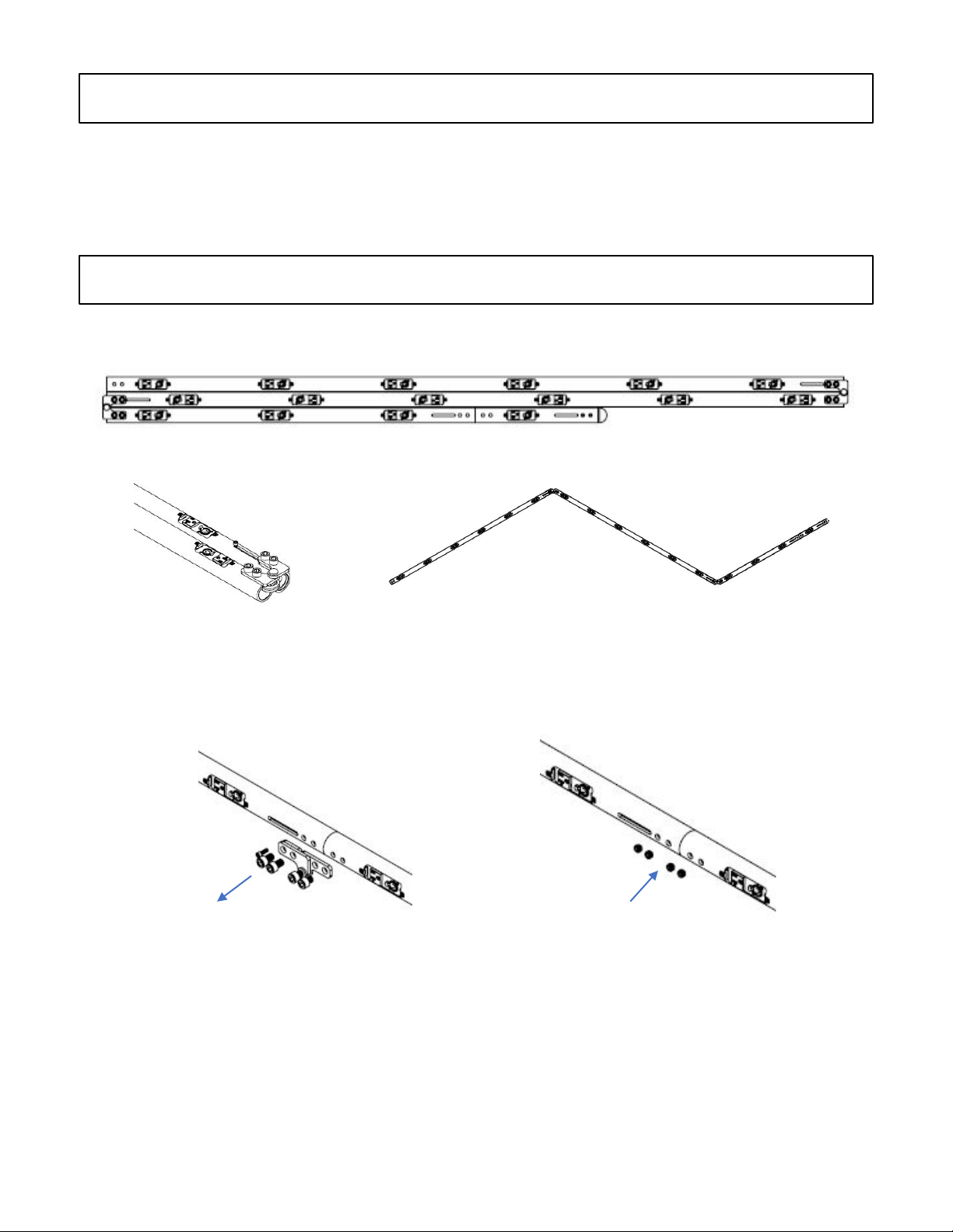
When you receive your MEGABATTEN, it will be folded at the hinges for shipping.
Carefully unfold the batten at the hinges, ensuring that the internal wires do not get pinched.
When the batten is unfolded, use a 3/8” hex key wrench and loosen the hinge bolts. Slide the splices
into place. A¼” cap screw is provided to use as a handle. Remove the bolts securing the hinges. Once
removed, discard the hinges and the bolts that were securing the hinges. Then install the provided 1/2”
set screws to secure the splices in the installed position. Once the splices are installed, use a 3/16” hex
key wrench to remove all ¼” cap screws from the splices and discard.
Once the batten has all the splices installed, it is ready to be installed into position.
REMOVE HINGE
AND HARDWARE
INSTALL ½
SET SCREWS

INSTALLATION
Mechanical Installation of the MEGABATTEN
The MEGABATTEN has been designed to be installable using all industry standards with regards to
batten installation. The 1.5” MEGABATTEN is listed to support a load of 30 pounds per linear foot when
supported on a maximum of 8-foot centers. The 2” MEGABATTEN is listed for 50 pounds per linear foot
when supported on a maximum of 8-foot centers.
We recommend the following hardware for a Dead Hung Batten installation.
CAUTION! PRIOR TO INSTALLATION, VERIFY WITH A STRUCTURAL ENGINEER THAT
SUPPORTING STRUCTURAL ELEMENTS ARE CAPABLE OF SUPPORTING THE MEGABATTEN AT
MAXIMUM LOAD. PLEASE ENSURE THAT RIGGING IS IN COMPLIANCE WITH LOCAL BUILDING
CODES AND SAFETY PRACTICES.
Mega-Folding Batten Clamp
Rated for 1675 Lbs, the Mega-Folding Batten Clamp is hinged for convenience and uses a single 7/16”
hex bolt to secure a light batten. It has a ½” clearance hole for rigging hardware.
Mega-Folding
Batten Clamp
Mega-Folding Batten Clamp
with threaded rod adapter.
Options available for 1/2” or
3/8” threaded rod.
Mega-Folding Batten
Clamp with 5/16” shackle
for wire rope and chain
rigging applications.
Installation using the Mega-Folding Batten Clamp
1. First, identify all rigging positions where the MEGABATTEN will be supported.
2. Assemble the Mega-Batten Clamp around the MEGABATTEN.
3. Attach the rigging hardware to the Mega-Batten Clamp.
4. Verify the orientation of the MEGABATTEN, then tighten all hardware.

MAKING ELECTRICAL CONNECTIONS
Connecting Power
There are four options for Power input into the batten.
19 Pin Male Circular Connector (Socapex) – This connector comes pre-wired ready to connect to a
female connector
SO Cable –The number of circuits determines the number of conductors, either 12/3, 12/4, or 12/5.
The length of cable extending beyond the batten is fixed at the factory according to approved
drawings. A connector is not supplied, so choose a connector that will meet code requirements in your
area.
Terminal Box –The batten will have a terminal with a terminal strip for connection of wires.
Extended Internal Conductors – The end of the batten has a ¾” NPT threaded socket for electrical
fittings. The conductors will need to be enclosed in conduit provided by others. Each power circuit
will have a hot and neutral conductor (up to six circuits), and there will be one ground that is shared by
all circuits. Connection to building power should be done by a licensed electrician. See the color code
chart for circuit conductor colors.
SO Cable
Extended Internal conductors
Terminal Box
ELECTRICAL CONNECTIONS MAY ONLY BE MADE BY INDIVIDUALS
FAMILIAR WITH THE CONSTRUCTION AND OPERATION OF THIS
PRODUCT AND THE HAZARDS INVOLVED.
19 Pin Connector
Maintenance
The MEGABATTEN requires very little maintenance once installed. The MEGABATTEN has a powder coat
finish so it can be wiped down with a damp cloth to remove accumulated dust. In the event of a damaged
outlet, turn off power to the MEGABATTEN. A replacement can be ordered and repaired on site by a
qualified individual.
Table of contents


