Altinex UT Series User manual

Under the Table Interconnect Solutions
Under the Table Interconnect SolutionsUnder the Table Interconnect Solutions
Under the Table Interconnect Solutions
User’s Guide
400-0491-004
1
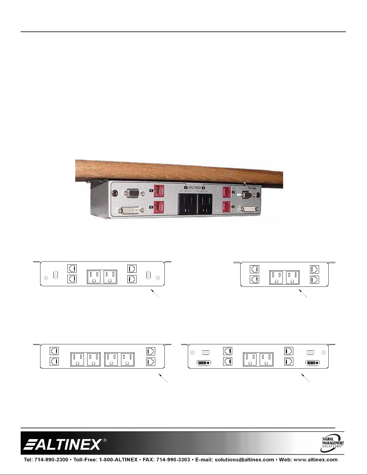
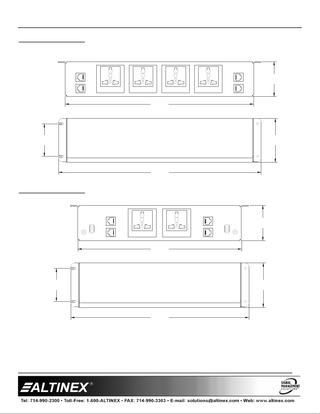
Installation Options
Inside Desk (Side View)
Table Top (Side View)
Back of Desk/Podium (Top View)
Desk Surface
Welcome!
We greatly appreciate your purchase of a UT Series. We are sure you will find
it reliable and si ple to use. Superior perfor ance for the right price, backed
by solid technical and custo er support is what ALTINEX has to offer.
We are co itted to providing our custo ers with
Signal Manage ent Solutions
®
to the ost de anding audiovisual
installations at very co petitive pricing and we welco e you to join the ranks
of our any satisfied custo ers throughout the world.
1. Precautions and Safety Warnings
Please read this anual carefully before using your UT-Series Interconnect.
Keep this anual handy for future reference. These safety instructions are to
ensure the long life of your UT-Series Interconnect and to prevent fire and
shock hazards. Please read the carefully and heed all warnings.
1.1 General
•There are no user serviceable parts inside. Qualified ALTINEX service
personnel ust perfor all service on the UT-Series.
1.2 Handling
•To prevent fire or shock, do not expose this unit to water or oisture.
Do not place the UT-Series in direct sunlight, near heaters, or
heat-radiating appliances, or near any liquid. Exposure to direct sunlight,
s oke, or stea can har internal co ponents.
•Handle the unit carefully. Dropping or jarring can cause da age.
•Do not pull any cables that are attached to the UT-Series.
•Do not place heavy objects on top of the UT-Series.
1.3 Cleaning
•Unplug the UT-Series before cleaning.
•Clean only with a dry cloth. Never use strong detergents or solvents such
as alcohol or thinner. Do not use a wet cloth or water to clean the unit.
Do not open the unit to clean.
1.4 FCC Notice
•This device co plies with Part 15 of the FCC Rules. Operation is subject
to the following two conditions: (1) This device ay not cause har ful
interference, and (2) this device ust accept any interference received,
including interference that ay cause undesired operation.
•This equip ent has been tested and found to co ply with the li its for
a Class A digital device, pursuant to Part 15 of the FCC Rules. These
li its are designed to provide reasonable protection against har ful
interference when the equip ent is operated in a co ercial
environ ent. This equip ent generates, uses, and can radiate radio
frequency energy and if not installed and used in accordance with
instructions found herein, ay cause har ful interference to radio
co unications. Operation of this equip ent in a residential area is
likely to cause har ful interference in which case the user will be
required to correct the interference at his own expense.
•Any changes or odifications to the unit not expressly approved by
ALTINEX, Inc. could void the user’s authority to operate the equip ent.
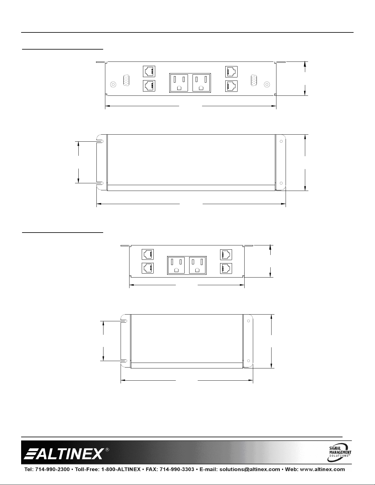
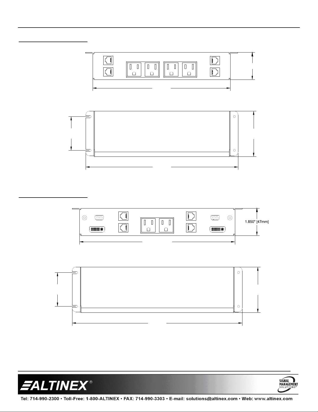
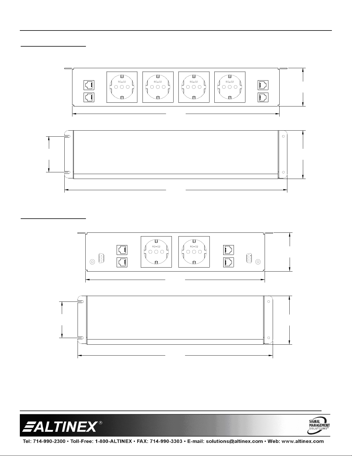
2. Installation Procedures
The UT Series can be installed horizontally or vertically as shown. Typically, units are installed under a table-top, but in
so e cases, it ay be desirable to install a unit inside a desk opening, or on the back of a desk or podiu .
Step 1. Locate the best position for the UT Interconnect, but do NOT ount it to the surface until all the cables are
prepared.
Step 2. Prepare the ating cables using high-quality cables for best results and durability. Make sure the cables are long
enough to allow for a service-loop and so the cables can be neatly routed beneath the table to their destinations.
Step 3. Prepare the network cables using the CAT-6 (RJ-45) connectors provided with the unit.* The connectors are
high-quality snap-in connectors and do not require any tools for installing the into the UT interconnect.
Step 4. Secure the unit under the table using the etal screws provided with the unit.
Step 5. Make any necessary connections to the snap-in connectors.
Step 6. Use cable-ties to secure the cables to the ounting shelf. Insert the ties through the holes on the botto of the
unit.
Step 7. Use the cable cla ps provided to secure the cables to the botto of the table/desk.
* Please visit our website: www.altinex.co for infor ation related to the pin out of the cables.
3. Limited Warranty/Return policies
Please see the ALTINEX website at www.altinex.co for details on warranty and return policies.
Note:
Connectors are provided but do not include cables. ALTINEX
reco ends a teleco unications contractor wire the network
connectors and verify operation before installing the UT
interconnect.

UT Series
UT SeriesUT Series
UT Series
User’s Guide
400-0491-004
2
4. Technical Specifications
Specifications are subject to change. See www.altinex.co for up-to-date infor ation.
Features/Description UT-Series
Pass-Through
Connection Type
(front to back)
AC Power NEMA Receptacle to plug
8 ft (2 m) cord
Stereo Audio 3.5 mm F-F
8 in (200 mm) cable
Network (CAT-6) Snap-in RJ-45 connector,
no cable
Video, Analog 15-pin HD bulkhead, F-F
Video, Digital 24-pin DVI bulkhead, F-F
Models
(Options)
UT240-311 (U.S.) CAT-6 (RJ-45) female (4)
AC receptacle (2)
UT240-313 (U.S.)
15-pin HD female (2)
24-pin DVI female (2)
3.5mm stereo (2)
CAT-6 (RJ-45) female (4)
AC receptacle (2)
UT240-310 (U.S.)
UT240-411 (EUR)
UT240-451 (ENG)
UT240-511 (AUS)
UT240-551 (UNIV)
15-pin HD female (2)
CAT-6 (RJ-45) female (4)
3.5mm stereo (2)
AC receptacle (2)
UT240-312 (U.S.)
UT240-410 (EUR)
UT240-450 (ENG)
UT240-510 (AUS)
UT240-550 (UNIV)
CAT-6 (RJ-45) female (4)
AC receptacle (4)
15A Circuit Breaker (1)
Accessories Included
Hardware Mounting screws
Table 1. UT240 Series General
Mechanical UT-Series
Dimensions See the Application Diagrams.
Net Weights
UT240-310 3.0 lb (1.4 kg)
UT240-311 2.4 lb (1.1 kg)
UT240-312 2.9 lb (1.3 kg)
UT240-313 3.0 lb (1.4 kg)
UT240-410 3.2 lb (1.5 kg)
UT240-411 3.0 lb (1.4 kg)
UT240-450 3.0 lb (1.4 kg)
UT240-451 3.0 lb (1.4 kg)
UT240-510 3.2 lb (1.5 kg)
UT240-511 3.0 lb (1.4 kg)
UT240-550 3.2 lb (1.5 kg)
UT240-551 3.0 lb (1.4 kg)
Shipping Weights
UT240-310 3.4 lb (1.5 kg)
UT240-311 2.8 lb (1.3 kg)
UT240-312 3.3 lb (1.5 kg)
UT240-313 3.4 lb (1.5 kg)
UT240-410 3.6 lb (1.6 kg)
UT240-411 3.4 lb (1.5 kg)
UT240-450 3.4 lb (1.5 kg)
UT240-451 3.4 lb (1.5 kg)
UT240-510 3.6 lb (1.6 kg)
UT240-511 3.4 lb (1.5 kg)
UT240-550 3.6 lb (1.6 kg)
UT240-551 3.4 lb (1.5 kg)
T°Operating 10°C-35°C
T°Maximum 50°C
Humidity 90%non-condensing
Table 2. UT240 Series Mechanical
Electrical TM-Series
Pass-Through Signals All standard audio, video, network,
and modem signals are acceptable.
Pass-Through AC 600W max.
Table 3. UT240 Series Electrical

UT Series
UT SeriesUT Series
UT Series
User’s Guide
400-0491-004
3
UT240-313 shown here.
5. About Your UT Interconnect
The ALTINEX UT-Series of Under-the-Table AV Interconnects provide a wide variety of options for routing co puter audiovisual signals, network connections,
and AC power. Under-the-table options are ideal for situations where it is too expensive or i practical to install the routing interface directly into the furniture.
UT-Series are available in both U.S. and international versions. U.S. versions provide standard NEMA 5-15R receptacles; international units include AC
receptacles for Europe, England, and Australia. Additionally, the UT240-550 and UT240-551 include universal AC receptacles that accept various types of AC
plugs.
U.S. and international odels UT240-312, UT240-410, UT240-450, UT240-510, and UT240-550 also include a push-to-reset 15A circuit breaker.
Each unit co es standard with AC receptacles and 4 RJ-45 connectors. The UT240 connects to standard AC power outlets through a single 8 ft (2 ) power cord
that is per anently attached to the unit. The CAT-6 (RJ-45) connectors are snap-in style connectors that attach to a support bracket on the inside of the
faceplate; they are not bulkhead style connectors. The connectors ust be "snapped" out of the bracket, wired to the CAT-5/6 cable, and then "snapped" back.
Units with audio inputs have 3.5 fe ale inputs on the front of the unit and 3.5 fe ale inputs on the back via an 8 in (200 ) cable. The audio
receiving devices attach to the cable on the back of the unit.
Units with video connectors have fe ale-to-fe ale bulkhead connectors for both 15-pin HD and 24-pin DVI types. The video receiving devices attach to the
bulkhead connectors accessible on the back of the unit.
UT240-310 UT240-311
UT240-312 UT240-313
AC (2)
Net (4)
Net (4)
AC (4) Net (4)
AC (2)
Net (4)
AC (2)
DVI-I (2)
VGA (2)
Audio (2)
VGA (2)
UT240-411 Europe
UT240-511 Australia UT240-451 England
UT240-551 Universal
UT240-510 Australia
UT240-410 Europe UT240-450 England
UT240-550 Universal
* The circuit breaker is located on the inside of the left-hand side
of each unit as viewed from the front. (see Diagram 14)
Circuit Breaker (1)

UT Series
UT SeriesUT Series
UT Series
User’s Guide
400-0491-004
4
6. Application Diagrams
Diagram 1: Typical Setup
UT240-310 Shown Above
UT240 Series

UT Series
UT SeriesUT Series
UT Series
User’s Guide
400-0491-004
5
Diagram 2: UT240-310 U.S./Canada
Diagram 3: UT240-311 U.S./Canada
3.095"
[79mm]
1.850"
[47mm]
9.400"
[239mm]
10.400"
[264mm]
2.300"
[58mm]
2.300"
[58mm] 3.095"
[79mm]
1.850"
[47mm]
6.636"
[169mm]
7.636"
[194mm]

UT Series
UT SeriesUT Series
UT Series
User’s Guide
400-0491-004
6
Diagram 4: UT240-312 U.S./Canada
Diagram 5: UT240-313 U.S./Canada
1.850" [47mm]
10.400"
[264mm]
2.300"
[58mm] 3.095"
[79mm]
9.400"
[239mm]
10.596" [269mm]
11.596"
[295mm]
2.300"
[58mm] 3.095"
[79mm]

UT Series
UT SeriesUT Series
UT Series
User’s Guide
400-0491-004
7
Diagram 6: UT240-410 Europe
Diagram 7: UT240-411 Europe
14.294"
[363mm]
2.300"
[58mm] 3.095"
[79mm]
13.294"
[338mm]
2.450"
[62mm]
12.400"
[315mm]
2.300"
[58mm] 3.095"
[79mm]
2.450"
[62mm]
11.400"
[290mm]

UT Series
UT SeriesUT Series
UT Series
User’s Guide
400-0491-004
8
Diagram 8: UT240-450 England
Diagram 9: UT240-451 England
14.294"
[363mm]
2.300"
[58mm] 3.095"
[79mm]
13.294"
[338mm]
2.450"
[62mm]
12.400"
[315mm]
2.300"
[58mm] 3.095"
[79mm]
2.450"
[62mm]
11.400"
[290mm]

UT Series
UT SeriesUT Series
UT Series
User’s Guide
400-0491-004
9
Diagram 10: UT240-510 Australia
Diagram 11: UT240-511 Australia
13.294"
[338mm]
14.294"
[363mm]
2.300"
[58mm] 3.095"
[79mm]
2.450"
[62mm]
3.095"
[79mm]
2.450"
[62mm]
11.400"
[290mm]
12.400"
[315mm]
2.300"
[58mm]

UT Series
UT SeriesUT Series
UT Series
User’s Guide
400-0491-004
10
Diagram 12: UT240-550 Universal
Diagram 13: UT240-551 Universal
13.294"
[338mm]
14.294"
[363mm]
2.300"
[58mm] 3.095"
[79mm]
2.450"
[62mm]
3.095"
[79mm]
2.450"
[62mm]
11.400"
[290mm]
12.400"
[315mm]
2.300"
[58mm]

UT Series
UT SeriesUT Series
UT Series
User’s Guide
400-0491-004
11
Diagram 14: Circuit Breaker
Model nu bers UT240-312, UT240-410, UT240-450, UT240-510, and UT240-550 include a 15A circuit breaker. The circuit breaker is located in the sa e
location for each odel. The UT240-312 is shown here.
CIRCUIT BREAKER
Push to reset.

UT Series
UT SeriesUT Series
UT Series
User’s Guide
400-0491-004
12
7. Operation
The UT-Series requires no adjust ents for perfor ance. Once set-up, the
UT-Series will work trouble-free without user intervention.
7.1 Circuit Breaker Reset
The UT240-312, UT240-410, UT240-450, UT240-510, and UT240-550
include a push-to-reset 15A circuit breaker. The circuit breaker is
accessible fro the left-hand side of the unit as viewed fro the front.
In the event the circuit breaker is tripped, do the following:
•Disconnect all AC devices fro the UT240
•Turn off the power switch of each AC device
•Push the circuit breaker reset button back in
•Reconnect the AC devices
•One at a ti e, turn on the AC devices
WARNING
WARNINGWARNING
WARNING
If the circuit breaker trips again, find the device that is drawing
excessive current. Check the ratings for each of the devices connected
to the UT240. If a device requires a significant a ount of power, it
should be plugged into its own supply circuit.
8. Troubleshooting Guide
We have carefully tested and found no proble s in the supplied UT-Series;
however, if you experience any proble s or have questions, call ALTINEX
at (714) 990-2300.
This manual suits for next models
12
Table of contents
Other Altinex Cables And Connectors manuals

Altinex
Altinex RT300-155 User manual

Altinex
Altinex RT300-126 User manual

Altinex
Altinex Tilt'N Plug TNP100 User manual

Altinex
Altinex RT300-125 User manual

Altinex
Altinex RT300-125 User manual

Altinex
Altinex RT300-121 User manual

Altinex
Altinex Tilt'nPlug TNP600 Series User manual

Altinex
Altinex RT300-125 User manual

Altinex
Altinex DA103-301 User manual

Altinex
Altinex RT300-121 User manual