HRS GT50 Series Instruction Manual

TITLE:
GT50 Series Guideline
REVISION DATE:
HIROSE ELECTRIC CO.,LTD.
OBJECT
PRODUCT:
GT50 SERIES
Figure number
ETAD-T0931-00
PAGE: 1 OF 13
GT50 Series
Guideline for Designing and Handling
COUNT
DESCRIPTION OF REVISIONS
DESIGNED
CHECKED
DATE
TITLE
GT50 Series Guideline for Designing and Handling
APPROVED
HK.UMEHARA
20220210
CHECKED
OM.MIYAMOTO
20220210
DESIGNED
YT.TAKANASHI
20220210
WRITTEN
RS.TAKAGI
20220210
TECHICAL SPECIFICATION
ETAD-T0931-00
△
0
HIROSE ELECTRIC CO.,LTD.
Apr.1.2022Copyright2022HIROSEELECTRICCO.,LTD.AllRightsReserved.
TITLE:
GT50 Series Guideline
REVISION DATE:
HIROSE ELECTRIC CO.,LTD.
OBJECT
PRODUCT:
GT50 SERIES
Figure number
ETAD-T0931-00
PAGE: 2 OF 13
Number Page
1.Introduction ................................................................................................................. 3
1.1 Purpose of this Guideline ...................................................................................... 3
2. Safety Precautions and Environmental Conditions ........................................................ 3
2.1 Safety Precautions ............................................................................................... 3
2.2 Environmental Condition....................................................................................... 5
3. Product Number Structure and Name .......................................................................... 6
3.1 Product Number Structure .................................................................................... 6
3.2 Product Name ..................................................................................................... 7
4. Product Specifications and Characteristics .................................................................... 8
4.1Series Specs ........................................................................................................ 8
4.2 Crimping Applicator .............................................................................................. 8
4.3 Recommended PCB Pattern, Reflow Profile .............................................................. 9
5. Handling and Precautions ........................................................................................... 10
5.1Connecting Method............................................................................................. 10
5.2 Removal Method ................................................................................................ 10
5.3Precautions when Mated...................................................................................... 11
5.4 Harness Condition............................................................................................... 11
5.5 Crimping Quality Standard, Harness Procedure ....................................................... 12
Revision history .......................................................................................................... 13
Apr.1.2022Copyright2022HIROSEELECTRICCO.,LTD.AllRightsReserved.
TITLE:
GT50 Series Guideline
REVISION DATE:
HIROSE ELECTRIC CO.,LTD.
OBJECT
PRODUCT:
GT50 SERIES
Figure number
ETAD-T0931-00
PAGE: 3 OF 13
1. Introduction
1.1 Purpose of this Guideline
The GT50 series guidelines are intended to provide information on precautions regarding
equipment design and work regarding the product features and handling methods of GT50.
These guidelines are intended to provide general information and do not limit your design or
guarantee results under all circumstances.
If you do not meet these guidelines, please contact us individually.
In addition, the photos and illustrations shown are those of our representative products,
so they may differ depending on the product.
The guideline information is subject to change without notice.
2. Safety Precautions and Environmental Conditions
2.1 Safety Precautions
Before using (operation / maintenance / inspection), please read all the precautions and operation
guideline to ensure correct use.
In this GT50 series guideline, the rank of safety precautions is classified as "WARNING"/"CAUTION".
■Meaning of "WARNING" and "CAUTION"
WARNING
Indicates a dangerous situation such as a fire, or the contents
that may cause death or serious injury if mishandled.
CAUTION
Indicates the contents that may cause minor injury or
property damage if mishandled.
・Be sure to turn off the power before connecting or disconnecting the connector, as there is a
risk of electric shock or damage.
・Do not touch the conductive parts. There is a risk of electric shock.
・Do not use with a voltage or current that exceeds the rating. It may cause fire or electric
shock.
・Do not use contacts other than those specified. There is a risk of poor contact and ignition.
・If the contact is deformed or has a large scratch, stop using it. It may cause poor contact
and ignition.
Please carry out the wiring work according to our wiring procedure manual. If the wiring
method is incorrect, there is a risk of poor continuity, ignition or damage.
WARNING
Apr.1.2022Copyright2022HIROSEELECTRICCO.,LTD.AllRightsReserved.

TITLE:
GT50 Series Guideline
REVISION DATE:
HIROSE ELECTRIC CO.,LTD.
OBJECT
PRODUCT:
GT50 SERIES
Figure number
ETAD-T0931-00
PAGE: 4 OF 13
・Do not use in situations where vibration or impact that exceeds the product specifications of
our products is applied.
・Do not use a damaged or missing connector.
・Do not ride on the connector or place heavy objects on it. There is a risk of damage.
・Follow this guideline when inserting and removing the plug. Incorrect operation may
damage the connector.
Please check if the lock is completed before use. If the lock is not completed, there is a risk
of poor continuity, disconnection of the plug, and damage.
・When removing the plug, make sure that the lock is completely unlocked.
・When routing the cable, bend it gently so that the connector and cable are not overloaded.
・When using the cable in a long harness state, fix it so that the vibration load of the cable is
not applied to the connector.
Do not store or use this product under conditions that contain corrosive substances that may
cause deterioration of plastic properties or metal rust.
If it is unavoidable to apply a solvent to this product to strengthen insulation or protect it,
make sure that the physical properties of the plastic do not deteriorate before using it.
・Do not use in an environment where it is constantly exposed to oil mist, oil water, corrosive
gas, flammable gas and dust.
・This product is designed for indoor use and should not be used outdoors.
・This product does not take any measures against salt damage.
Use the specified crimp contact, and check in advance that there is no deformation, oil, etc.,
and that there is no abnormality in contact resistance before use.
Do not store or use this product near the sea or under conditions that contain a lot of salt.
If the metal is significantly rusted or discolored, replace it with a new one.
・Store and use this product under conditions that do not freeze or condense.
・This product is designed for use in the internal connection of equipment, so please do not
use it for any other purpose.
※Please check the product specifications and product variations of this product from our website.
Homepage address:https://www.hirose.com/
CAUTION
Apr.1.2022Copyright2022HIROSEELECTRICCO.,LTD.AllRightsReserved.
TITLE:
GT50 Series Guideline
REVISION DATE:
HIROSE ELECTRIC CO.,LTD.
OBJECT
PRODUCT:
GT50 SERIES
Figure number
ETAD-T0931-00
PAGE: 5 OF 13
2.2 Environmental Condition
Operating temperature: -40 ° C to + 125 ° C (Include the temperature rising by current)
Storage temperature: -40 ° C to + 125 ° C (storage conditions after mounting)
Operating humidity: 95% RH or less
Atmosphere: Indoors (not exposed to direct sunlight),oil mist,corrosive gas,flammable gas,no dust
Storage period: Within 6 months from the date of shipment
Storage temperature: 15 to 30 ° C (storage conditions before unpacking)
Storage humidity: 40-60% RH (storage conditions before unpacking)
Apr.1.2022Copyright2022HIROSEELECTRICCO.,LTD.AllRightsReserved.

TITLE:
GT50 Series Guideline
REVISION DATE:
HIROSE ELECTRIC CO.,LTD.
OBJECT
PRODUCT:
GT50 SERIES
Figure number
ETAD-T0931-00
PAGE: 6 OF 13
3. Product Number Structure and Name
3.1 Product Number Structure
Please use it when you judge the product specifications from the product name.
■Receptacle
GT50 - 2 P –1 H
①②③ ④⑤
■Plug
Socket
GT50 - 2 S - 1 C
①②③ ④⑤
GT50 - 28 SCFA
①⑥⑦
①Series Name
GT50
②Number of Pins
2
③Connector Type
S: Female Side Connector
P: Male Side Connector
④Pitch
1.0mm
⑤Part Type
C: Socket
H: Right Angle SMT Type
⑥Applicable Wire Size
28:AWG#28(sq 0.08 ㎟)
⑦Form Type /
Packaging Type
SCF:Female Connector
Crimp Contact / Reel Packaged Product
Apr.1.2022Copyright2022HIROSEELECTRICCO.,LTD.AllRightsReserved.
TITLE:
GT50 Series Guideline
REVISION DATE:
HIROSE ELECTRIC CO.,LTD.
OBJECT
PRODUCT:
GT50 SERIES
Figure number
ETAD-T0931-00
PAGE: 7 OF 13
3.2 Product Name
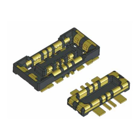
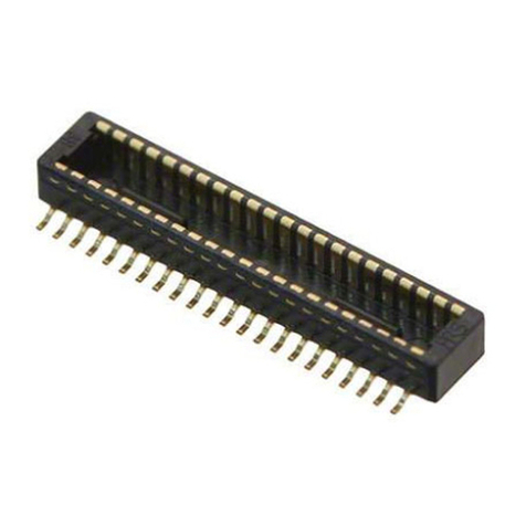
【Receptacle】
*Since the lot number is engraved on the edge of the upper surface,
please set the adsorption area to avoid that part.
【Socket】
【Crimp Contact】
Apr.1.2022Copyright2022HIROSEELECTRICCO.,LTD.AllRightsReserved.
TITLE:
GT50 Series Guideline
REVISION DATE:
HIROSE ELECTRIC CO.,LTD.
OBJECT
PRODUCT:
GT50 SERIES
Figure number
ETAD-T0931-00
PAGE: 8 OF 13
4. Product Specifications and Characteristics
4.1 Series Specifications
■Material and Finish
Component
Material
Color / Finish
Receptacle
Housing
LCP
Black
Header Contact
Brass
Gold plated(Contact and SMT Lead Area Only)
Metal Fitting
Brass
Tin Plated
Plug
Socket
PBT
Black
Crimp Contact
Corson Alloy
Gold Plated(Contact and SMT Lead Area Only)
■Performance Characteristics
Rated Voltage
60V AC/DC
Rated Current
2,4 pos:2 A
6,8,12,16 pos:1.5A
Operating Temperature *
-40℃~+125℃
Contact
Resistance
Initial
30mΩMax. (20mV, 0.1mA)
After Environmental Test
50mΩMax. (20mV, 0.1mA)
Insulation Resistance
500MΩMin. (100V DC)
Withstanding Voltage
300V AC(for 1 minute)
Applicable
Cable
Wire size
0.08sq.
Insulation Diameter
φ0.7~φ 0.8mm
Durability
10 cycles(Insertion / Withdrawal)
Lock Strength
25N Min.
*:Includes the temperature rise due to current flow.
The temperature rise value (derating curve) varies depending on the number of cores,
so please contact our sales staff for details.
The above characteristics are typical values. Please check each product
specification sheet for details.
4.2 Crimp Applicator
・Please use a original HRS crimping applicator to crimp the crimp contact.
・Perform regular maintenance on the crimping tools to ensure crimping quality.
Crimping Applicator (for Mounting Automatic Crimping Machine (CM-105C))
Product Name
HRS No.
Applicator Product Number
Applicator HRS No.
GT50-28SCFA
760-1001-0-00
AP105-GT50-28S
901-5257-0-00
Note1:The crimp height of the contact is set for each cable type. In addition, regarding the quality of the
crimping state, we have prepared a crimping quality standard for each contact.
Please contact our sales staff for details.
Note2:Please note that it may take some days for the new cable to have a new crimp height setting.
When purchasing original HRS equipment, please contact our sales staff to see if the cable you plan
to use for the target contact has been evaluated.
Apr.1.2022Copyright2022HIROSEELECTRICCO.,LTD.AllRightsReserved.
TITLE:
GT50 Series Guideline
REVISION DATE:
HIROSE ELECTRIC CO.,LTD.
OBJECT
PRODUCT:
GT50 SERIES
Figure number
ETAD-T0931-00
PAGE: 9 OF 13
4.3 Recommended PCB Pattern, Reflow Profile
■Recommended PCB Pattern
Unit:mm
■Recommended Reflow Profile
This temperature profile is for reference under the following setting conditions. It may vary
depending on the type of cream solder, manufacturer, board size, and other conditions such as
mounting materials, therefore please check the mounting condition carefully before use.
Apr.1.2022Copyright2022HIROSEELECTRICCO.,LTD.AllRightsReserved.

TITLE:
GT50 Series Guideline
REVISION DATE:
HIROSE ELECTRIC CO.,LTD.
OBJECT
PRODUCT:
GT50 SERIES
Figure number
ETAD-T0931-00
PAGE: 10 OF 13
5. Handling and Precautions
5.1 Connecting Method
When connecting the plug to the receptacle, insert the plug perpendicular to the mating face.
If you accidentally hit the corner of the plug against the center of the receptacle, or if it fits
diagonally to the fitting portion, the housing and s may be deformed.
5.2 Removal Method
When removing the plug from the receptacle, push down the lock on the plug side in the figure
below with your finger, and then pull the plug side to remove it.
If you push the lock part while pulling the plug side, unexpected force will apply to the connector,
and the cable may come off or the housing may be deformed.
Also, when pulling the plug side, pull it out while grasping the socket so that no force is applied to
the cable.
Apr.1.2022Copyright2022HIROSEELECTRICCO.,LTD.AllRightsReserved.
TITLE:
GT50 Series Guideline
REVISION DATE:
HIROSE ELECTRIC CO.,LTD.
OBJECT
PRODUCT:
GT50 SERIES
Figure number
ETAD-T0931-00
PAGE: 11 OF 13
5.3 Precautions when Mated
When mating, make sure that the receptacle is not subject to a strong load of 25N or more.
(Prying, pulling, etc.)
The receptacle may peel off from the board or the plug may come off.
5.4 Harness Condition
■When the harness length is short
If the harness length is too short(Less than 50mm) as (shown) figure below, there is a risk that
a load will be applied to the connector due to twisting of the cable, therefore confirm the
orientation of the connectors at both ends. (Please consider the mounting direction and
manufacture the harness.)
Apr.1.2022Copyright2022HIROSEELECTRICCO.,LTD.AllRightsReserved.
TITLE:
GT50 Series Guideline
REVISION DATE:
HIROSE ELECTRIC CO.,LTD.
OBJECT
PRODUCT:
GT50 SERIES
Figure number
ETAD-T0931-00
PAGE: 12 OF 13
■Harness Routing
Please refrain from using the cable in a state where it is always bent from
the end of the housing.
Check the cable specifications and set the minimum bending radius (R) of the cable.
■Cable Tape Winding
When wrapping the cable with tape, wrap it with tape at least 30 mm away from the bottom of
the crimp socket neck. Please wrap at least 30mm away.
If you bundle the cables close to the root, the wires at the ends may be pulled and the cables
may come off.
5.5 Crimping Quality Standard, Harness Procedure
・GT50-28SCFA Crimping Quality Standard (Document No.ATAD-T0925-00)
・GT50 series Harness Operation Manual (Document No.ETAD-T0930-00)
Apr.1.2022Copyright2022HIROSEELECTRICCO.,LTD.AllRightsReserved.
TITLE:
GT50 Series Guideline
REVISION DATE:
HIROSE ELECTRIC CO.,LTD.
OBJECT
PRODUCT:
GT50 SERIES
Figure number
ETAD-T0931-00
PAGE: 13 OF 13
【Revision History】
Revision
Date
Designed
Checked
Comment
0
2/10/2022
RS.TAKAGI
OM.MIYAMOTO
First edition
Apr.1.2022Copyright2022HIROSEELECTRICCO.,LTD.AllRightsReserved.
Other manuals for GT50 Series
1
Table of contents
Other HRS Cables And Connectors manuals

HRS
HRS DF62W EP 2.2C Series User manual

HRS
HRS BM25 Series Instruction Manual

HRS
HRS ZE064W Series User manual

HRS
HRS HELIX User manual

HRS
HRS EM30MSD Series User manual

HRS
HRS FH12-20S-0.5SH(54) User manual

HRS
HRS DF62W Series User manual

HRS
HRS DF57 Series User manual

HRS
HRS GT36 User manual

HRS
HRS FH67 Series User manual