The Wine Square CUBE LT User manual

CUBELT
User Manual

DESIGNED AND MADE IN CANADA

1
TABLE OF CONTENTS
Warning / Caution / Note Definition 2
Introduction 4
Conditions In The Wine Cellar 4
Description of Components 5
Minimum Requirements 9
Location Selection 10
Installation 10
ROUGH-IN 11
FINAL INSTALLATION 15
System Start-Up 24
Use 28
Temperature Adjustment 29
Adjusting the Alarm Sound Level 29
Settings 30
Screen Unlock 32
Control with a Device on the Same Network 32
Remote Connection 33
Maintenance 34
Cleaning the Water Chiller Filter 34
Add Water 35
Water Replacement 37
Troubleshooting 38
Failure identified by a system error code 38
Failure Without System Error Code 46
APPENDICES 50
Wall Pre-Closure Checklist 51
PARTS LIST 53
Control Box CUBELT 54
RC4LT 55
NOTES 56

2
The words WARNING, CAUTION and NOTE have special meanings and should be
carefully reviewed.
WARNING Alerts the reader to a situation which, if not avoided, could result
in death or serious injury. It can also describe potential serious side effects
and their safety risks.
CAUTION Alerts the reader to a potentially hazardous situation which, if not
avoided, may result in minor or moderate injury to the user or damage to
the product or other property. This includes the special precautions neces-
sary for the safe and effective use of the device and the precautions necessary
to avoid damage to a device which may occur as a result of use or misuse.
NOTE : Provides special information to facilitate maintenance or clarify impor-
tant instructions.
WARNING
• DO NOT operate the unit through an electrical outlet and/or wall outlet that is damaged
or improperly secured to the wall. If the supply cord is damaged, it must be replaced by
the manufacturer or an authorized service agent.
• DO NOT cover or obstruct the air intake and exhaust of the CUBELT , Water Cooler and
CUBE-RC4LT while in use.
• This appliance is not intended for use by children. Children should be supervised and
should not play with or around the appliance.
• DO NOT place objects or sit on system modules..
• Always switch off and unplug the appliance when cleaning or servicing.
• DO NOT run power cord under carpet or rug.
• Use caution to avoid tripping over system wires or tubing.
3
• DO NOT use in areas where gasoline, paint or other flammables are stored.
• Basic safety precautions should always be taken when using electrical appliances.
• DO NOT use an extension cord with this appliance.
• Do not insert fingers or other foreign bodies inside the air grilles. This could cause
accidents due to the rotation of the blades.
• To ensure correct operation of the appliance in safe conditions, it is absolutely forbidden
to expose it to atmospheric agents and direct heat sources. The temperature in the
rooms where the appliance is installed must be between 10°C and 38°C (50°F - 100°F).
CAUTION
• If service is required, contact an authorized service agent.
• DO NOT place objects or sit on system modules.
• Install the Water Cooler in a well ventilated area.
• Unplug the appliance when stored or not in use.
• Use caution to avoid tripping over system wires or tubing.
• This appliance has been manufactured for the air conditioning of a wine cellar and must
not be used for any other purpose.
• STRICTLY use the installation hardware provided by The Wine Square. DO NOT attempt
to install or connect this device using any methods other than those provided in this
manual. Improper installation could void any existing warranty.

4
Introduction
This manual will help you operate or maintain the CUBELT wine cellar air con-
ditioning unit. Read this manual carefully before installing, using or servicing this
product.
The CUBELT wine cellar air conditioner is the most advanced compressor system on the
market. Specially designed for shallow glazed wine cellars where the air conditioning unit is
located directly above the bottles. It uses a water loop refrigeration which reduces thermal
shock while preventing air drying. This three-module unit allows for easy and flexible instal-
lation for residential or commercial projects.
Although the air conditioning system has great importance in maintaining adequate condi-
tions for serving or storing wine, it is not the only element to consider. It is very important
to ensure that the wine cellar is adequately insulated and sealed against humidity before
installing the CUBELT .
Conditions In The Wine Cellar
The CUBELT wine cellar cooling system is a system designed to maintain a temperature
in the wine cellar between 54°F-65°F [12°C-18°C]. It does not allow to obtain very cold
temperatures as for the service of champagnes and certain white wines. Its air condition-
ing mechanism is designed to reduce the large temperature differences affecting the wine
between each stop/start of the compressor. It also reduces air drying in the wine cellar that
can cause corks to deteriorate.
Studies show that the temperature of a wine cellar should be between 10°C and 18°C with a
humidity between 50%-80%. The lower the cellar temperature, the slower the wine will age.
A temperature that is too low will block its ageing.
The Wine Square recommends a temperature setpoint of 14°C (57°F) with this device, which
corresponds to both an aging temperature and a tasting temperature for most red wines.
5
Description of Components
1
2
3
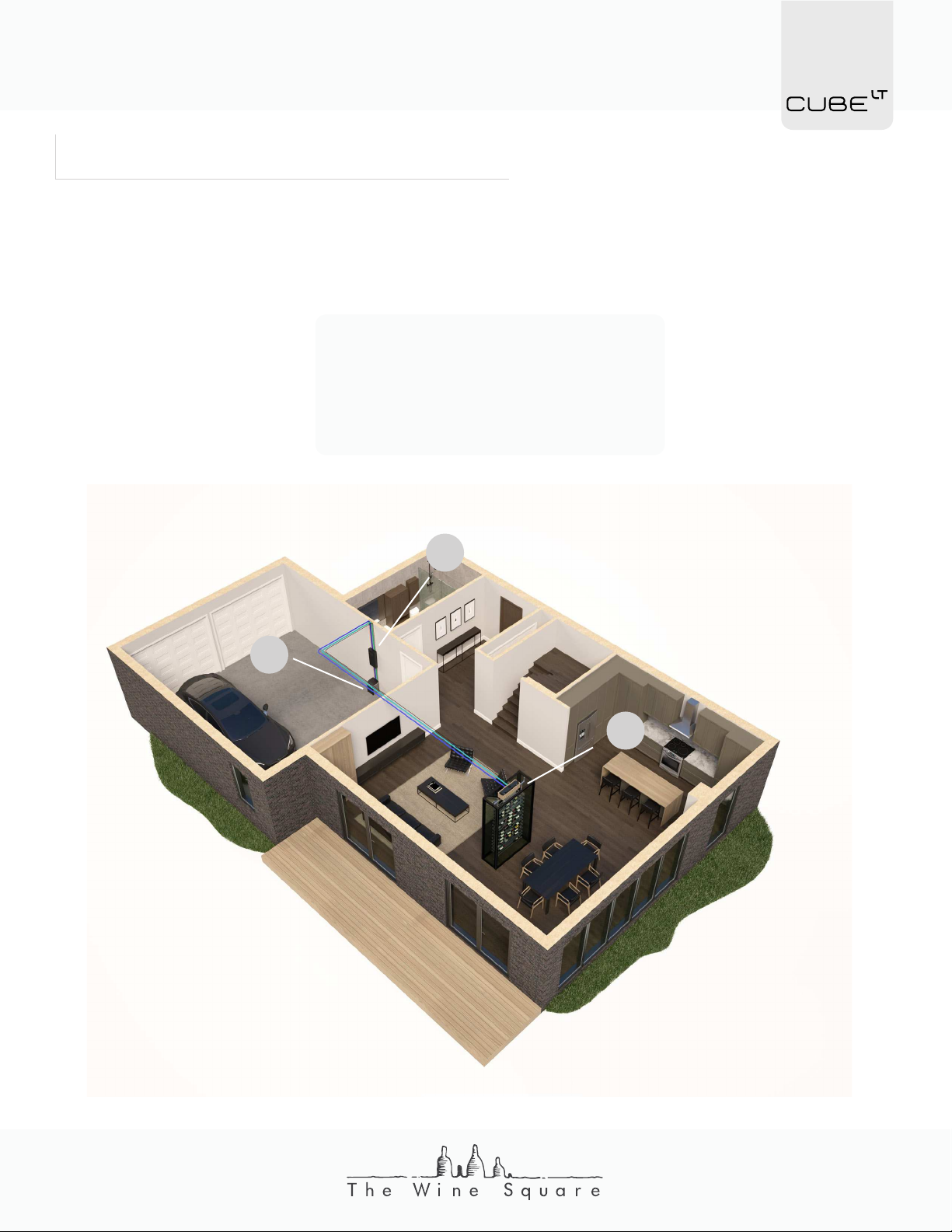
The CUBELT is a “split” cooling system made up of three components. It allows the noisy
element (the compressor) to be placed at a distance from the wine cellar.
1- CUBELT CONTROL BOX
2-CUBELT WATER CHILLER
3-RC4LT DIFFUSER

6
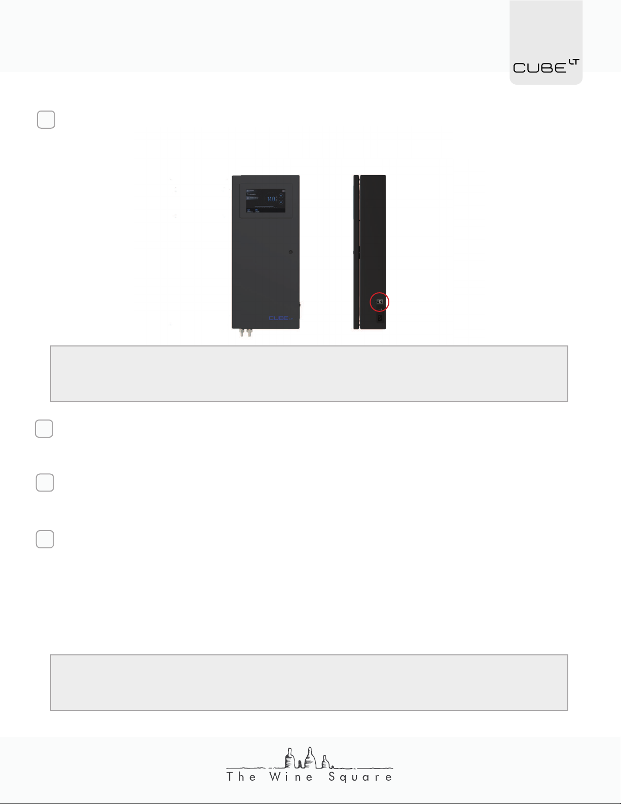
The CUBELT Control Box is the unit managing the system. Equipped with a high-resolution
7” touch screen, it allows the display and simple adjustment of the conditions of the wine
cellar. It provides the electrical power and the chilled water to the RC4-LT module in the
wine cellar by means of a network wire and two 1/2” PEX pipes. The CUBELT Control Box
must be connected to a closed circuit chilled water source coming either from the CUBELT
Water Chiller or from a plate heat exchanger connected to the chilled water of the building.
Very ecological and safe, it uses no refrigerant gas and therefore always recirculates the
same water. It is normally installed in a garage or mechanical room.
CONTROL BOX
Voltage____________________________________________
Amperage_______________________________________
Power_______________________________________________
Plug_________________________________________________
Inlet / Outlet___________________________________
Maximum Water T° ________________________
Minimum Water T°__________________________
Flow Rate________________________________________
Internet Connection________________________
120V 60Hz
0.75 A
90W
NEMA 5-15P
1/2” PEX
48°F (9°C)
32°F (0°C)
20 L/min
RJ45
SPECIFICATIONS

7
The CUBELT Water Chiller provides the chilled water necessary for the proper functioning
of the system. Italian designed, this small, robust and eco-friendly unit uses R290 as refrig-
erant, a non-toxic gas with zero ODP (Ozone Depletion Potential) and very low GWP (Global
Warming Potential). This chiller is installed near the CUBELT Control Box in a mechanical
room or garage usually. Its sound level, similar to that of a dehumidifier, means that it is not
recommended for use in an apartment or condo without a mechanical room.
WATER CHILLER
Voltage____________________________________________
Amperage_______________________________________
Power Consumption_______________________
Cooling Power_________________________________
Plug_________________________________________________
Inlet/Outlet Connection_________________
Weight_____________________________________________
Minimum Water T°__________________________
Refrigerant______________________________________
Ambient Operatoing T°__________________
Certification____________________________________
120V 60Hz
3.6 A
330W
400W
NEMA 5-15P
1/2” PEX
47lb (21.4 kg)
41°F (5°C)
R290
50°F - 100°F (10°C-38°C)
UL / CE
SPECIFICATIONS
8
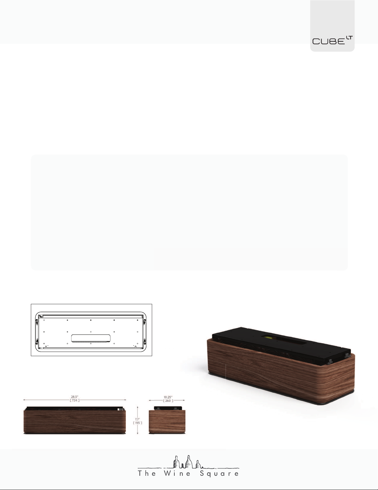
The RC4LT is the cooling unit of the system positioned at the ceiling of the wine cellar.
It pumps the heat in and carries it to the water cooler. It is equipped with a condensate
pump to evacuate the condensation outside the wine cellar. The RC4LT must be installed
horizontally at the highest point of the wine cellar. For a large wine cellar or a particular
geometry, it may be necessary to install more than one RC4LT, they are then connected
in series on the communication and water supply level.
RC4LT DIFFUSER
Power / Communication_________________
Cooling Power_________________________________
Drain Connection____________________________
Inlet/Outlet Connection_________________
Minimum Clearance
Front (A)_______________________________
Side (B)_________________________________
Back (C)________________________________
Under the device__________________
RJ45
400W
1/2” PEX
1/2” PEX
1.75’’
1”
1’’
8’’
SPECIFICATIONS
A
B
C
Front
Back

9
Minimum Requirements
In order to ensure proper operation of the system as well as to maintain the warranty, it is
important that the wine cellar is built according to the rules of the art. These requirements
remain the same, regardless of the size of the wine cellar.
GENERAL
• Vapor barrier or moisture barrier on all surfaces (walls / floor / ceiling)
• Airtight
WALLS
• Minimum insulation of R15 or U0.06
FLOOR
• Minimum insulation of R7.5 or U0.13
CEILING
• Minimum insulation of R7.5 or U0.13
GLASS
• Minimum insulation of R4.5 or U0.22 with LOW-E protection
CAUTION Insulation under a concrete slab does not count as floor insulation. Unless
the slab of the wine cellar is independent from the rest of the building and has a
thermal break of at least 1”. Otherwise, the thickness of the concrete slab acts as a ther-
mal bridge and injects heat around the entire perimeter of the wine cellar.
In addition to voiding the warranty on the Water Chiller failure to comply with these condi-
tions exposes you to, but is not limited to:
Condensation on wine cellar glasses
Poor humidity control in the wine cellar
Reduced compressor life
Bad conditions for aging wine
Compressor frequent stop/start
A lack of system power to reach the target temperature
10
Installation
The installation of the CUBELT is normally done in two steps, one before the walls are
closed and one when the system is put into operation. The first step is to install the pipes,
communication cable and wood blocking necessary for the system to work properly in the
walls. This installation procedure uses PEX, a flexible and easy to install product to connect
the different units. The system can be installed with other types of piping. Contact The Wine
Square if you would like another type of conduit for installation. Refer to the regulations in
your area/building before using plastic conduit such as PEX.
Location Selection
Before starting the installation of the system, it is important to select the location where the
various components will be installed. Although air conditioning systems push cold air when
they are in use, these devices work more to remove heat, colder air is only a result. The nu-
ance seems small, but it is very important when evaluating the placement of the compo-
nents of the air conditioning system. Indeed, assuming that the system is a heat pump:
THE RC4LT : This unit seeks to remove heat from the wine cellar, so it will need
to be located at the hottest location in the wine cellar, the ceiling. Depending on
the configuration of the room, it can be either in the center or above the door. A
clearance of at least 8’’ must be kept under the appliance to allow the service of
this unit.
THE WATER CHILLER: The compressor system used to produce cold water for the
wine cellar, this is the unit that will reject the heat removed from the wine cellar.
It can be located up to 30 meters (100 feet) from the wine cellar. This unit could
experience reduced power if it is in an overheated room. Heat rejection will then
be more difficult. It is therefore necessary to find a well-ventilated location that will
maintain an annual temperature between 50°F and 100°F (10°C - 38°C). This unit
is not designed for outdoor installation. This unit is also the “noisy” module of the
system. It emits a noise comparable to a window air conditioner. The ideal location
for this module is the mechanical room or the garage.
THE CONTROL BOX: The control box can be located anywhere between the water
chiller and the wine cellar. It is usually installed above the water chiller.

11
PEX 1/2’’ PIPE
2X INSULATED
PEX 1/2’’ PIPE
ETHERNET
RJ45-CAT6
RC4-LT *
CONTROL BOX *
CUBE°LT
WATER CHILLER
CUBE°LT
ETHERNET WALL
PLATE LINKED TO
INTERNET
SOCKET NEMA 5-15R,2P
DEDICATED CIRCUIT
DRAIN
ROUGH-IN
A
B
C
D
E
F
G

12
APosition RC4LT in the wine cellar. It is important to consider the thickness of the insula-
tion, finishing material and glass envelope when locating the final location of the unit.
Check that the clearance necessary for the correct operation of the unit is respected.
B
Minimum Clearance
Front (A)____________________________
Side (B)_________________________________
Back (C)_____________________________
1.75’’
1”
1’’
A
C
Front
Back
Install a wood blocking at least the size of the unit and at least 5/8’’ thick at the loca-
tion of the unit. Provide an opening of maximum 2’’x 10’’ tangent with the middle of the
location of the unit, for the passage of the tubes. Generally two holes of 1-3/4 ‘’ and one
of 0.75 ‘’ are sufficient.
28.5”
[ 724 ]
10.25”
[ 260 ]
Install 2 x 1/2” insulated PEX pipes between the location of the control box (usually locat-
ed in the garage or mechanical room) and the outlet of the RC4LT unit (opening made
in the wood blocking installed previously) .
Put “duct tape” type adhesive tape between the different sections of insulation (joint)
covering the tubes.
B
NOTE : It is preferable to use PEX tube supports rather
than elbows when a 90° is required.

13
Install 1/2” non-insulated PEX pipe between a drain (the drain can be in the garage or
mechanical room since the unit is equipped with a condensate pump) and the outlet of
the RC4LT unit.
Install an elbow at the RC4LT location as in step B’. It is best to connect the other end
of the tube to an open drain (e.g. floor drain) to prevent the risk of odor coming from
the sewers in the wine cellar. Connecting to a drain using a ‘’P-trap’’ principle to prevent
odors is not effective, as the system may never generate condensation if the humidity
in the house is well managed, the ‘’ P-trap’’ would thus end up drying up.
C
2’’-6’’
[50-150]
At the ceiling in the wine cellar, leave between 2” and 6” of tubing hanging from the ceil-
ing and install an elbow on each conduit.
B’
NOTE : It is preferable not to exit all the tubes at the same height to facilitate the
connection of the system during its final installation. It is also possible to hang lon-
ger tubes at this stage and install the elbows only during the final installation of the
RC4LT after the walls are closed.
NOTE : To bring the conduits out of the wall in the mechanical room in an aesthetic
way, it is possible to use a low voltage 2-gang wall bracket.
14
Install an RJ45 network wire with minimum 23AWG wires between the RC4LT and the
control box location. Allow a minimum of 36” of wire to hang in the wine cellar and the
length needed to connect to the right side of the control box.
D
NOTE : It is more prudent at this stage to run a second RJ45 wire away from the
first. In the event that the first is damaged by a nail or screw when closing the
walls, the second can be used.
Install an RJ45 network socket connected to the internet near the device. The CUBELT
uses a wired connection to connect to the internet.
E
Have a professional install a NEMA 5-15R, 2-pole electrical outlet on a dedicated circuit
for powering the control box and the water cooler.
F
Install a nailing backing on the wall at the location of the control box. The nailing bottom
must be at least 36” high and 10” wide. The top of the bottom nailing panel must be
installed 60” above the ground.
G
NOTE : Before closing the walls, take the time to review the “Check List” in the
appendix to make sure that nothing has been forgotten.
15
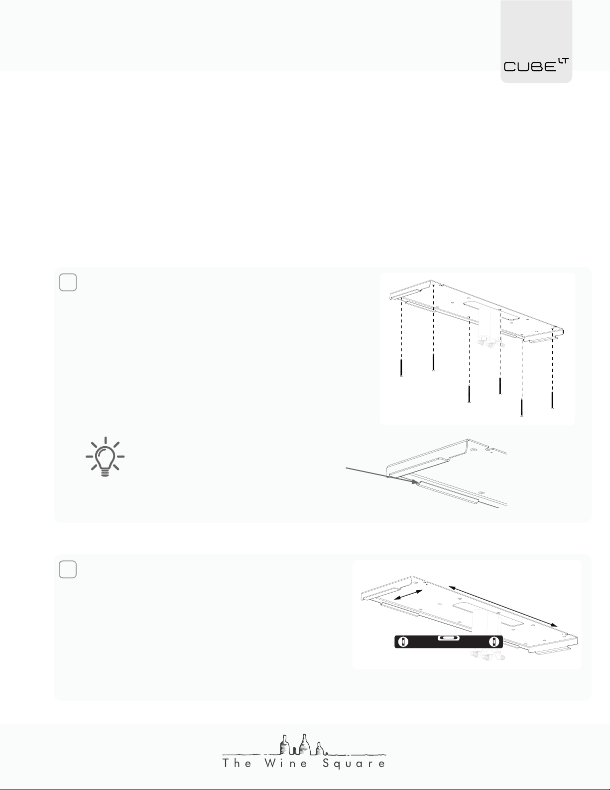
2Check that the backing plate is level in
both axes. If necessary, use shims be-
tween the ceiling and the plate to level
everything. If the support is not level, the
condensation generated by the system
may drip to the floor rather than being
picked up by the condensation pump.
FINAL INSTALLATION
This installation step must be carried out at the very end of the work when there is no lon-
ger any dust production. Otherwise, dust could damage the device and reduce the cool-
ing capacity of the system. In the event that construction steps are required following the
installation of the system, please unplug the device before starting work.
FINAL INSTALLATION RC4LT
1Locate the RC4LT in the wine cellar. Using
# 8 flat-head wood screws, long enough to an-
chor into the nailing base without risking drilling
the PEX tubes installed in the ceiling, secure the
RC4LT backing plate. Take the time to make sure
the plate is parallel with the walls.
The bended edge of the mounting
plate should be the side of the plate
closest to the back wall of the wine
cellar.

16
3Install the radiator module on the support plate. Be careful not to trap the tubes
when rotating the module.
4Secure the radiator in place with two # 8 flat head wood screws long enough to
anchor into the nailing base.

17
5Connect the tubes previously installed in the walls with the radiator module. The
tubes preinstalled on the radiator are connected directly to the PEX fittings without
a crimp ring. The tube is therefore installed on the PEX tip as it will be on a barb
fitting.
Insulated Tube Non-insulated Tube
Make sure that the connection with the tubes is above the condensation
pan. Otherwise, take care to insulate the PEX and fitting to avoid condensa-
tion.
6Install a connector at the end of the RJ45 wire and connect the wire to the RC4LT
electronic board. The wire can be plugged into any of the two connectors on the
board.
CAUTION Be sure to always test your cable with an RJ45 cable tester be-
fore plugging the wire into the device. Reversing two wires when installing
the connector could damage the product electronics.

18
7Install the wooden box over the radiator. Before sliding the casing into place, find
the joint on the wood veneer and orient that surface toward the back of the wine
cellar. When putting the housing back in place, make sure the tubes are not kinked.
Once the wood box is in place, turn the support fins to hold it in position. Make sure
the fins are securely in place and lightly pull on the wood casing to make sure the
part is firmly in place.
Table of contents
Other The Wine Square Wine Cooler manuals


