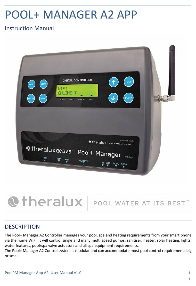
Theralux POOL+ MANAGER User manual

1
POOL+ MANAGER INSTALLATION & SETUP GUIDE
INSTALLATION
Master Controller & Expansion Unit/s Installation
Find a suitable location to mount the control box. Ideally, as with all pool
equipment, it should be installed out of direct weather and no closer than 3
metres from the water’s edge, at a minimum 600mm above ground. The power
cable is 1.8m long and should be plugged directly into a general power outlet,
not into an extension lead.
Fix the mounting bracket to a solid structure via screws and wall plugs kit
provided, and slide the controller on, locking into place.
To remove unit, lift and gently pull away from mounting bracket.
Do Not turn the power on to the Master Controller or the Expansion Units until all the
following criteria has been met.
Install Pool sensor as per instructions on page 3 of the manual.
Install Roof sensor (if option chosen) as per instructions on page 3 of the
manual.
If required, fit and install any Valves Actuators that are required to run the
system. Plug the cable from the Valve Actuator/s into the Valve sockets located
beneath the Master Controller (see diagram located on p4 of the manual for
location). Up to 4 Valve Actuators can be installed and controlled.
If a Gas Heater or Heat Pump is installed, then connect either the Heater
Interlock cable or the Pump Call cable as per the instructions under HEATER
CONTROL on p2 of the main instruction booklet.
REMEMBER: If the heater’s flow or pressure switch circuit is 240Vac, an external relay
can be purchased separately and is to be installed (KIT09) by a licensed electrician.
Plug the communication cable from Expansion Unit 1 (if optioned) beneath the
Master Controller. (see diagram on page 4]
Plug the communication cable from Expansion Unit 2 (if fitted) beneath the
Expansion Unit 1. (see diagram on p4)
Plug in the Filtration Pump. If you have a variable speed pump, go to the next
page to see the required wiring diagram for the brand/series of pump to be
used.
If the pump installed is a Reltech or Insnrg, a motor cable will need to be purchased
separately.
If the filtration pump is a single speed pump, plug directly into one of the
power sockets located on either the Master Controller or on an Expansion Unit.
The pump may be plugged into the Sanitiser outlet and the Sanitiser plugged
into the controller power outlet.
Plug all other appliance power cables that will be controlled by the POOL+
MANAGER into the power points located beneath the Controllers and ensure
maximum current loads are not exceeded.

5 PIN PUMP CONNECTION PLUG
THERALUX
(TVS PRO &
THERAFLO)
RELTECH
Pin 1 Pin 2 Pin 3 Pin 4 Pin 5
Common Speed Speed Speed Speed
Black Wire Red Wire Brown Wire Green Wire White Wire
THERALUX
(THERAFLO
S-SERIES) 485
RELTECH 485
Pin 1 Pin 2 Pin 3 Pin 4 Pin 5
Not Used Not Used A B 0 V
Green Wire White Wire Black Wire
PENTAIR VS/F
Pin 1 Pin 2 Pin 3 Pin 4 Pin 5
Not Used Not Used A B Not Used
Yellow Wire Green Wire
DAB
Pin 1 Pin 2 Pin 3 Pin 4 Pin 5
IN 0 Not Used Negative Positive Not Used
Red Wire Black Wire Brown Wire
INSNRG
Pin 1 Pin 2 Pin 3 Pin 4 Pin 5
Not Used Not Used A B Not Used
Orange Wire White/Orange
Striped Wire
Pin 1 Pin 1
Pin 3 Pin 3
Pin 5 Pin 5
Pin 2 Pin 2 Pin 4 Pin 4
When the pump plug is out of
the controller, it will be like this.
When the pump plug is flipped
over and plugged into the
controller, it will look like this.

SETUP
This sequence must be followed:
Turn the controller on at the power point, wait for 20 seconds before
turning the power onto the first Expansion Unit. Wait a further 20 seconds before
turning on the second Expansion Unit, if fitted.
This sequence is to ensure that the Master Controller recognises the Expansion
Units in the correct order. Do this within the first 2mins while the Master Controller
is actively scanning. The WiFi Indicator should be slowly FLASHING
Go to APP GUIDE – next page
If setting up though the controller start at the Installer menu and follow through each
section.
Enter the menu as described in the manual move ↑ or ↓ to highlight Installer
Menu and press Enter.
Move through the Installer Menu options until 6.10 Expansion Unit is highlighted,
press Enter.
You are looking to ensure that the Master Controller has recognised that there is
Expansion boxes connected.
Press Enter, then use the ↑ or ↓ buttons to change the number of Expansion Units
required: 0, 1, or 2.
Once the amount you require is displayed, press Enter to accept.
Press Enter to accept NO for Resetting the Expansion addresses.
Once returned to Installer Menu, move to highlight 6.1 Appliances. Press Enter.
Move through the power sockets, valves and VF contact to assign appliances to them.
Sockets 3-5 are Expansion Units 1 and sockets 6-8 are Expansion Unit 2.
From there it will be a case of moving down through the rest of the Installer
Menu options, entering what is attached to the system and how it works in
conjunction with everything else.
Once everything within the system has been assigned, you can then move back to
the main menu and work through entering Filtration Times, Temperature Settings,
Timers, and Lights.
If you don't go through the Installer Setup first, the Main Menu will be limited.
Once the App has been installed and the QR code scanned, all settings can be
changed via the App on a phone.

POOL+ MANAGER A2 APP GUIDE
GETTING
SET UP
Before downloading the App for the POOL+ MANAGER controller, please ensure that
the controller has been turned on, the WIFI indicator is slowly flashing, and the setup
phone is connected to the 2.4 G home WiFi (setup will not work using 5 G)
Download the POOL+ MANAGER App
Scan the QR code on the front of this page or rear of main controller
Add the home WiFi password in Device Setup
You are now ready to set up appliances
DEVICE: there are several options that may be utilised.
QR Code: Scan or Share:
Scan – You can use this option to scan the QR code for the controller if your
phone doesn’t ask for the QR code to be scanned at initial startup of the App.
Share – A simple way to add users that have downloaded the App.
WiFi Connection: Setup – Enter Network Password
Installer Menu: Lock Access to the Installer Menu:
The Installer Menu can be locked once the system is set up to prevent
equipment settings accidently being altered by users who may not know how
the system works or needs to be set up. Doing this will only enable people with
the password to have access to the Installer Menu options. Once locked, the
Installer Menu options won’t be visible in the menu screen.
When you have locked the Installer Menu you will be asked to enter the
password to unlock the Installer Menu options. Once unlocked the Installer
Menu options will be visible to allow alteration.
Device Information: You can type the device name here and see all relevant
connection information and available UPDATES.
ADDITIONAL
INFORMATION
When completed the App will display all settings currently set in your controller.
From here you can select or alter any of the settings that are currently active in your
Master Controller.
Table of contents
Other Theralux Controllers manuals
Popular Controllers manuals by other brands
Water Analytics
Water Analytics AquaMetrix AM-2250 Installation and operation manual
Jabra
Jabra LINK 280 - quick start guide
Ironton
Ironton 41484 owner's manual
Mitsubishi Electric
Mitsubishi Electric Q03UDVCPU user manual

Kemo
Kemo M083 Mounting instructions + Setting into operation
Axis
Axis A1214 installation guide

Mitsubishi Electric
Mitsubishi Electric PAC-YT51CRB installation manual
iLumin
iLumin SC-RP Programming Guide & User Manual
ABB
ABB i-bus KNX product manual
TeSuCo
TeSuCo Oxyturbo Nitrogen 6000 operating instructions

Skov
Skov DOL 278CT user manual
Grundfos
Grundfos DID Series Installation and operating instructions
