ThermaFlo OzSaver 4000 User manual
4000
Thermaflo 88-B Industry Ave. Springfield, MA 11 4
8 -8484-CFC
TABLE OF CONTENTS
INTRODUCTION l
READ ME FIRST 2
SAFETY 4
RECOVERY
Liquid and Vapo Recove y Method 5
Push-Pull Liquid and Vapo Recove y Method 7
CHARGING OPERATION WITH HOT VAPOR 9
SELF-EVACUATION 10
SUB-COOL OPERATION 11
PURGING NON-CONDENSABLES (AIR) II
SWITCHING FROM ONE REFRIGERANT TO ANOTHER 11
TROUBLESHOOTING 12
SCHEMATICS 14
ILLUSTRATIONS
Figu e 1 OZsave ™¿¡^Cont ols 3
Figu e 2 Liquid and Vapo Recove y Method 6
Figu e 3 Push-Pull Liquid and Vapo Recove y Method 8
Figu e 4 Cha ging With Hot Vapo 9
UNITED STATES PATENT: 4766733
UNITED STATES PATENT: 4809515
UNITED STATES PATENT: 4981020
Other US and oreign Patents Pending
MODEL 4000
Theimaflo* 3640 Main Street • Springfield, MA 01107
THERMA LG is division of American THERMA LO Corporation Mar 1998
2436A0*

INTRODUCTION
Dea Custome :
THERMAFLO would like to thank you fo selecting the OZsave ™ Recove y & Cha ging Unit.
THERMAFLO is dedicated to designing, p oducing and ma keting the best p oducts in the indust y. We,
p oduce a full line of Recove y/Recycling & Cha ging equipment fo applications in:
• HVAC • appliance • automotive • automotive salvage
• gene al salvage • la ge indust ials • OEMS • mass & p ivate t anspo tation
• ef ige ated t ucks • building maintenance • institutions • packaging & p ocessing
You OZsave ™ unit, like all THERMAFLO p oducts, has gone th ough extensive testing to assu e
the highest deg ee of quality. THERMAFLO backs up this claim of quality with a comp ehensive
se vice p og am and a full wa anty.
The people at THERMAFLO have put a g eat deal of time, effo t and p ide in p oducing this p oduct.
We believe that ou continued diligence will assu e bette p oducts, se vices and satisfied custome s.
Thanks again fo you confidence in THERMAFLO!
Since ely,
m \.
Michael C.D. Fioretti, Jr.
President
2436AI-

READ ME FIRST
THERMAFLO's OZsave Recove y & Cha ging unit is a hyb id pumping system capable of
moving ef ige ant liquid and gas f om:
* ef ige ant system being se viced to a ecove y tank "
* ecove y tank to system being se viced
* new tank to a system being se viced
* one unit to anothe .
The hea t of the OZsave ™/^ unit is a comp esso designed to ope ate without oil in its c ankcase.
Lub ication is a function of the mate ials of const uction and the oil mist associated with the flow of
ef ige ant gas th ough the unit.
The comp esso is a patented di ect d ive open style unit which can ope ate f om 20 inches of HG to 125
psig. of inlet p essu e. The maximum discha ge p essu e switch is set at 425 psig. When 425 psig is
exceeded the unit will shut down.
Since the OZsave ™&/tZ unit has a di ect d ive, oil-less comp esso the e is not a conce n with ove heating
o ha ming the comp esso du ing extended ope ation. In o de to maximize the ecove y p ocess the
OZsave ™li^ l unit will not shut off automatically at a given low p essu e - the technician MUST shut off
the unit. This featu e allows the technician the ability to pull down the system being se viced to the desi ed
vacuum which, as a minimum, should be those equi ed by EPA.
The OZsave ™Ljl unit is App oved toUL 1963 by Unde w ite s Labo ato ies, to ecove ef ige ant
f om any ef ige ant system which uses ef ige ants 12,22,500,502 o 134a.
The OZsave ™jyi unit is Rated in Acco dance with ARI740-91..
Special Featu es
Indicato Lights - You OZsave ™^/, ecove y unit is equipped with High P essu e and Vapo indicating
lights.
The Vapo light indicates whethe the OZsave unit is ecove ing liquid o vapo ef ige ant. If the
OZsave ™^ unit is ecove ing vapo the Vapo light will be illuminated.
The High p essu e light wo ks in conjunction with the high p essu e shutoff. If the discha ge p essu e
eaches 425 psig., the OZsave ™«^ unit will shut off and the High P essu e light will be illuminated.
OZsave ™ LjU Inlet Filte
THERMAFLO equi es that a THERMAFLO filte pa t # ALF-052, standa d 052 o 053 filte d ie ,o
equivalent be used on the inlet side in o de to p otect the OZsave ™/^, unit f om pa ticulate damage.
If, du ing wa anty inspection, it has been dete mined that a filte was not used du ing the ope ation,
the OZsave ™£yW, unit wa anty will be voided.
2
2436A2-
OZsaver "fujll Helpful Hints
• If a se vice manifold is being utilized to access the equipment being se viced, the liquid
must be ecove ed fi st.
• When the OZsave ™ Ljll unit is switching f om liquid to vapo ecove y it will make a
epeated "clicking" sound. This is no mal ope ation.
• If the system being se viced does not equi e valve co e dep esso s in the hose, emove
them to accele ate the ecove y ate.
• P io to use, the ecove y tank should be evacuated to 1000 mic ons, using a vacuum
pump to eliminate non-condensables and to accele ate the ecove y p ocess.
• The OZsave ™,/,^ unit has a comp ession atio of 20 to 1 and can pull vacuums of
10 to 20 inches of Hg on a system even when pumping into a ecove y tank with high
p essu es. Howeve , it is possible to pull even deepe vacuums by eplacing the sto age
tank with a newly evacuated sto age tank at the end of the ecove y p ocess.
• If the ecove y tank is pa tially filled with ef ige ant p io to the ecove y ope ation: it
will be necessa y to sub-cool the ecove y tank (Refe to page 11). If the sub-cooling
ope ation is not pe fo med p io to the ecove y ope ation the ecove y ate will be
slowed down.
The illust ations in Figu e la e used in diag ams th oughout this manual to identify items and
featu es of the OZsave HufiL unit.
3
2436A3-
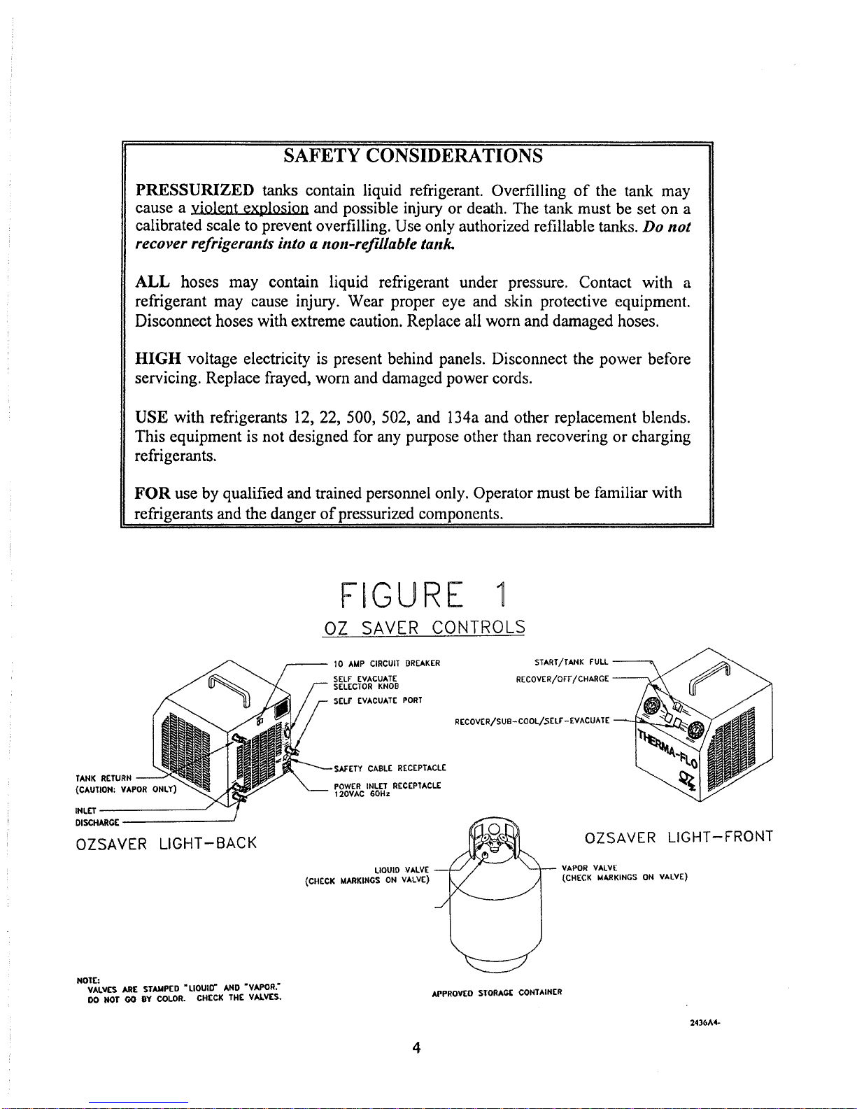
SAFETY CONSIDERATIONS
PRESSURIZED tanks contain liq id refrigerant. Overfilling of the tank may
ca se a violent explosion and possible inj ry or death. The tank m st be set on a
calibrated scale to prevent overfilling. Use only a thorized refiliable tanks. Do not
recover refrigerants into a non refillabte tank.
ALL hoses may contain liq id refrigerant nder press re. Contact with a
refrigerant may ca se inj ry. Wear proper eye and skin protective eq ipment.
Disconnect hoses with extreme ca tion. Replace all worn and damaged hoses.
HIGH voltage electricity is present behind panels. Disconnect the power before
servicing. Replace frayed, worn and damaged power cords.
USE with refrigerants 12, 22, 500, 502, and 134a and other replacement blends.
This eq ipment is not designed for any p rpose other than recovering or charging
refrigerants.
FOR se by q alified and trained personnel only. Operator m st be familiar with
refrigerants and the danger of press rized components.
______________________
TANK RETURN
(CAUTION: VAPOR ONLY)
INLET
DISCHARGE
OZSAVER LIGHT-BACK
NOTE:
VALVES ARE STAMPED "LIQUID" AND “VAPOR.”
DO HOT GO BY COLOR. CHECK THE VALVES.
FIGURE
OZ SAVER CONTROLS
10 AMP CIRCUII BREAKER
SEL EVACUATE
SELECTOR KNOB
SEL EVACUATE PORT
START/TANK FULL
RECOVER/OFF/CHARGE
RECOVER/SUB-COOL/SELF-EVACUATE
SA ETY CABLE RECEPTACLE
POWER INLET RECEPTACLE
120VAC 60Hz
LIQUID VALVE
(CHECK MARKINGS ON VALVE)
OZSAVER LIGHT- RONT
VAPOR VALVE
(CHECK MARKINGS ON VALVE)
APPROVEO STORAGE CONTAINER
24 36 A4«
4

LIQUID AND VAPOR RECOVERY METHOD
SERVICE MANIFOLD REQUIRED
(Refe to Figu e 2)
Before starting this operation, an empty tank m st be located on a calibrated scale. If a partially
filled tank is being sed, a s b-cooling operation m st be performed to improve recovery
performance. See page 11 for s b-cooling instr ctions.
1. PLUG in the power cord to a 110-120 VAC, 15 amp minim m s pply.
2. CONNECT a hose from the INLET port of the OZsaver™ AM nit to the center fitting
of the service manifold. Attention: a filte must be in this line o the wa anty is voided.
3. CONNECT a hose from the HIGH side access port of the system being serviced to the
HIGH side of the service manifold.
4. CONNECT a hose from the LOW side access port of the system being serviced to the
LOW side of the service manifold.
5. CONNECT a hose from the DISCHARGE port of the OZsavei™ JjM nit to the LIQUID
side of the recovery tank.
6. CONNECT a hose from the TANK RETURN port of the OZsaver™ *^ nit to the VAPOR
side of the recovery tank.
7. CONNECT the Safety Cable to the Recovery Tank.
8. OPEN:
HIGH side access valve on the system being serviced,
HIGH side of the service manifold,
DISCHARGE valve on the OZsaver™ nit,
INLET valve on the OZsaver« AM nit,
TANK RETURN valve on the OZsaver™ nit,
LIQUID valve on the tank,
VAPOR valve on the tank.
9. TURN the SELF-EVACUATION selector knob to OZsaver» Jft/ nit to the OFF position.
10. PLACE the RECOVER/SUB-COOL/SELF EVACUATE switch in the RECOVER
position.
11. PLACE the Recover/Charge switch into the Recover position.
12. PRESS the START b tton. The OZsaver™ nit will start r nning.
Once all of the liq id has been recovered from the high side of the system:
13. OPEN:
LOW side access valve on the system being serviced,
LOW side of the service manifold.
Once the recovery process is complete:
14. CLOSE all valves and place the RECOVER/OFF/CHARGE b tton in the OFF position.
15. Use the SELF EVACUATION OPERATION (See Page 10) to self-evac ate the
OZsaver™ nit.
2436A5-
5
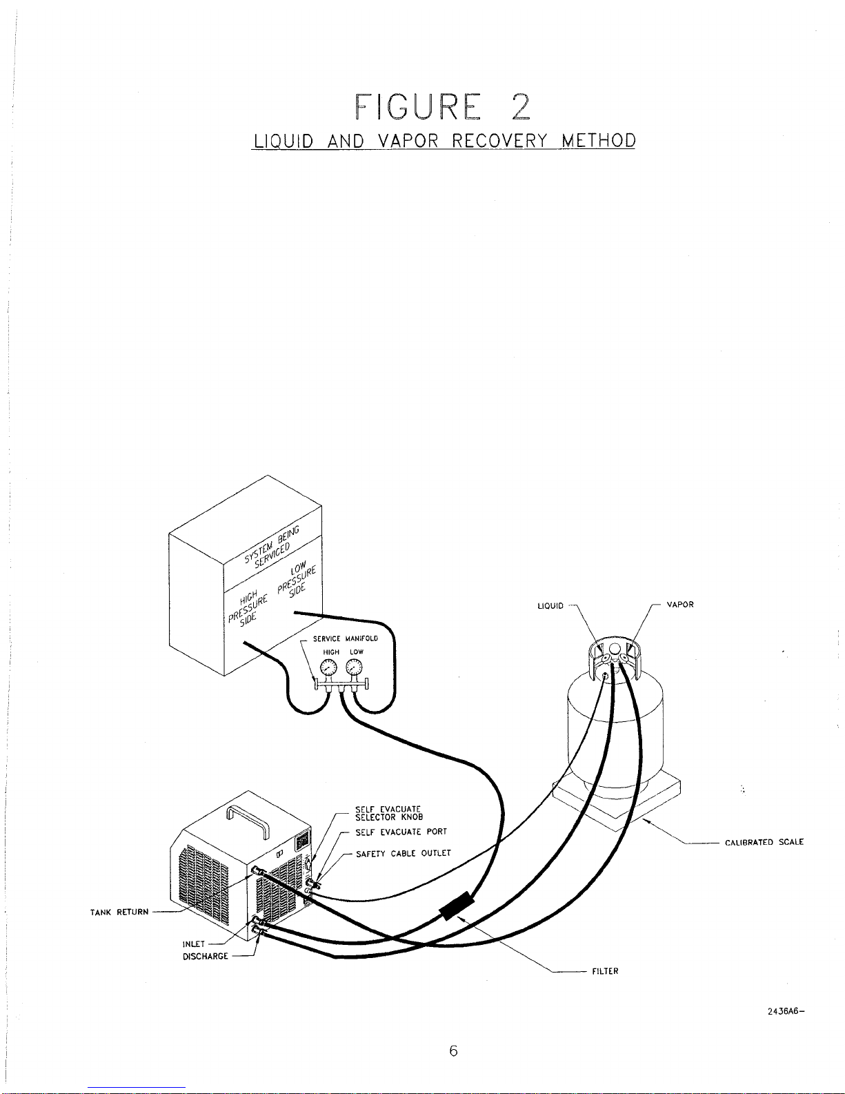
FIGURE 2
LIQUID AND VAPOR RECOVERY METHOD
VAPOR
TANK RETURN
FILTER
CALIBRATED SCALE
2436A 6-
6

PUSH-PULL LIQUID AND VAPOR RECOVERY METHOD
(Refe to Figu e 3)
If a partially filled tank is being sed, a s b-cooling operation m st be performed to improve recovery
performance. See page 11 for s b-cooling instr ctions.
1. PLUG in the power cord to a 110-120 VAC 15 amp. minim m s pply.
2. CONNECT a hose from the INLET port of the OZsaver™ A/A nit to the HIGH side access port of
the system being serviced. A filte must be in this line o the wa anty is voided.
3. CONNECT a hose from the SELF EVACUATE port of the OZsaver™ Ay/A nit to the LOW side
access port of the system being serviced.
4. CONNECT a hose from the DISCHARGE port of the OZsaver™ A // nit to the LIQUID side of the
recovery tank.
5. CONNECT a hose from the TANK RETURN port of the OZsaver™ A^A/ nit to the VAPOR side of
the recovery tank.
7. CONNECT the Safety Cable to the Recovery Tank.
8. PLACE the SELF-EVACUATION selector knob in the ON position.
9. OPEN:
HIGH side access valve on the system being serviced,
LOW side access valve on the system being serviced,
SELF EVACUATE valve on the OZsaver™ A /J nit,
TANK RETURN valve on the OZsaver« J f t/ nit,
INLET valve on the OZsaver« .^ nit,
DISCHARGE valve on the OZsaver™ A^J nit,
LIQUID valve on the recovery tank,
VAPOR valve on the recovery tank.
10. PLACE the RECOVER/SUB-COOL/SELF-EVACUATE switch in the RECOVER position.
11. PLACE the RECOVER/OFF/CHARGE switch into the Recover position.
12. PRESS the START b tton.
Once all of the liq id has been recovered:
13. PLACE the SELF EVACUATE selector knob in the OFF position.
The OZsaver™ A ft nit will now be recovering vapor.
Once the vapor recovery process is complete:
14. CLOSE all valves and PLACE the RECOVER/OFF/CHARGE switch into the OFF position.
7

FIGURE 3
PUSH-PULL LIQUID AND VAPOR RECOVERY METHOD
2436A8-
8

CHARGING OPERATION WITH HOT VAPOR
(Refer to Fig re 4)
1. PLUG in the power cord (m st be a 110-120 VAC, 15 amp minim m service).
2. CONNECT a hose from the SELF-EVACUATE port on the OZsaver”Itfi nit to the center port of
the service manifold.
3. CONNECT a hose from the TANK RETURN port on the OZsaver nit to the VAPOR side
of the recovery tank.
4. CONNECT the high side of the service manifold to the high side of the system being serviced.
5. CONNECT the low side of the service manifold to the low side of the system being serviced.
6. TURN the SELF-EVACUATE selector knob to the ON position.
7. OPEN:
HIGH side access valve on the system being serviced,
LOW side access valve on the system being serviced,
LOW side of the service manifold,
SELF-EVACUATE valve on the OZsaver Ml nit,
TANK RETURN valve on the OZsaver Miunit,
VAPOR valve on the recovery tank.
8. CLOSE:
INLET valve on the OZsaver Mi nit,
DISCHARGE valve on the OZsaver Mi nit,
LIQUID valve on the recovery tank,
HIGH side of the service manifold.
9. PLACE the RECOVER/SUB-COOL/SELF-EVACUATE switch into the RECOVER
position.
10. PLACE the RECOVER/OFF/CHARGE switch into the CHARGE position.
11. START the OZsaver™^ nit by pressing the START b tton.
When the charging process is complete:
12. SHUT OFF the OZsaver™^ nit.
13. CLOSE all valves.
FIGURE 4
9
2436A9-

SELF-EVACUATION
1. CLOSE all valves, incl ding tank valves. Make s re safety cable is connected.
If the PUSH-PULL recovery proced re is being sed contin e to step 2 otherwise go
to step 3.
2. REMOVE the hose that is connected between the SELF-EVACUATE port and the
LOW side of the system being serviced.
3. PLACE the RECOVER/SUB-COOL/SELF-EVACUATE switch into the SUB-COOL
position.
4. PLACE the RECOVER/OFF/CHARGE switch into the Recover position.
5. OPEN:
TANK RETURN valve on the OZsa^pr nit,
DISCHARGE valve on the OZsaver SiAl nit,
LIQUID valve on the recovery tank.
6. PRESS the START b tton.
Allow the OZsaver™&i/i nit to r n ntil the s ction press re ga ge reads 10 inches of Hg
or lower, then:
7. CLOSE:
LIQUID VALVE ON THE RECOVERY TANK,
DISCHARGE valve on the OZsaver ¿¡dJ, nit,
TANK RETURN valve on the OZsaver lufl nit.
8. TURN the OZsaver™IjM nit off by placing the RECOVER/OFF/CHARGE switch in
the OFF position.
9. DISCONNECT the tank ret rn hose from the TANK RETURN port and
CONNECT it to the SELF-EVACUATE DISCHARGE port.
10. TURN the SELF-EVACUATE selector knob to the ON position.
11. OPEN:
SELF-EVACUATE valve on the OZsaver nit,
VAPOR side of the recovery tank, TM
DISCHARGE valve on theOZsaver nit.
12. PLACE the RECOVER/SUB-COOL/SELF-EVACUATE switch into the SELF-
EVACUATE position.
13. PLACE the RECOVER/OFF/CHARGE switch into the Recover position.
14. START the OZsaver™iyi nit by pressing the START b tton.
15. ALLOW the OZsaver™/^, nit to r n ntil the s ction press re ga ge reads 10 inches
of Hg or lower.
16. CLOSE all valves.
17. TURN the OZsaver™iWi nit off by placing RECOVER/OFF/CHARGE switch
into the OFF position.
1
2436A10-
SUB-COOL
The S b-cool position on the rocker switch, located on the front of the OZsaver nit
allows the operator to S b-cool the storage tank when the OZsaver nit is connected
per the standard method or when sing a service manifold.
While in the Recovery Mode, move the rocker switch to S b-cool and the OZsaver™
LjkL nit will stop recovering refrigerant from the system being serviced and S b-cool the
storage tank. This is done witho t having to disconnect and reconnect hoses.
When the rocker switch is in the Recover position the OZsaver™JiyU, nit ret rns to the
normal recovery mode. k
The advantages of the S b-cool is that it allows the operator to red ce the press re in the
storage container. This enhances the recovery rates for both liq id and vapor. It also
allows the OZsaver™^ nit to p ll exceptionally low vac ms on the systems being
serviced (15 to 20 inches of Hg or better).
S b-cooling sho ld be done for approximately 5 to 10 min tes or ntil the operator feels
that the press re in the storage tank has been s fficiently red ced.
While the rocker switch is set to S b-cool the s ction press re gage is reading the
press re in the storage container. The longer the OZsaver hfi nit is S b-cooling, the
more the press re will drop. A press re drop of 20 psig. on the gage, from the time the
S b-cool process was beg n, will res lt in a significant increase in the recovery rate.
PURGING NON-CONDENSABLES (AIR)
While in the Recovery mode, se the following proced re to p rge the nit of air:
1. CLOSE the Inlet, Discharge and Tank Ret rn valves.
2. MOVE the rocker switch to Self Evac ate and follow the instr ctions for the Self
Evac ation operation described on page 10 in this man al.
NOTE: If deeper vac ms are req ired, a vac m p mp can be attached to the Self
Evac ate Discharge valve d ring this process.
SWITCHING FROM ONE
REFRIGERANT TO ANOTHER
Whenever the OZsaver nit is sed on two different refrigerants, the Self
Evac ation operation sho ld be sed prior to switching to the new refrigerant. The nit
sho ld then be r n on air in both the Recover and S b-cool modes for 30 seconds each to
p rge any resid al refrigerant. A final Self Evac ation operation sho ld then be
performed to remove the air from the OZsaver L nit.
11 2436AI I-

Model 4000 The maflo OZ Saver
Quick Test
"P eseason Check-out”
Run this test once a yea
O
When the unit seems to un but will not move any ef ige ant.
1. Plug in the powe co d to 110 vac, 15 amp minimum supply.
2. Attach the safety cable to a tank senso o use a The maflo test plug (Pa t # 1997-10).
3. TURN the SELF EVACUATE SELECTOR KNOB to the OFF position.
4. TURN the SELF EVACUATE BALL VALVE to the OFF position,
5. OPEN all (3) othe ball valves.
6. Place both ocke switches into the RECOVER positions and p ess the START button.
7. Unit is now unning.
A. The unit should be sucking in the INLET PORT. YES / NO
CLOSE: Inlet Po t
B. The unit should pull a 28” vacuum on the f ont SUCTION GAUGE. YES / NO
OPEN: Inlet Po t
Place the ocke switch in the SUB-COOL position.
C. The unit should be sucking in the TANK RETURN PORT. YES / NO
CLOSE: Tank Retu n Po t
D. The unit should pull a 28” vacuum on the f ont SUCTION GAUGE. YES / NO
OPEN: Tank Retu n Po t
Place the ocke switch back into the RECOVER position,
E. The unit should be sucking in the INLET PORT again. YES / NO
TURN the unit up-side-down on its handle
F. The unit should be sucking in the TANK RETURN PORT YES / NO
TURN the unit back up ight.
CLOSE: Discha ge Po t
G. The unit should build 150 psi on the f ont DISCHARGE GAUGE
within 30 seconds. YES / NO
Call The maflo custome se vice at 800-848-4232
Fo fu the t ouble-shooting assistiance.

J*.
—0 s
J -0
SrEH-Ow
tow
P8C55URC
SWJCH
I-
»2
i Tank &£
<j>D£q
Solenoid # 1 Solenoid #2 Solenoid #3 Solenoid #4
Liq id Recovery Open at 20
Psigo iess
At Wet
CLOSED OPEN OPEN
Vapor Recovery Same OPEN CLOSED CLOSED
S b-Cool Same CLOSED OPEN CLOSED
Self-Evac OPEN OPEN OPEN OPEN
Table of contents
Popular Test Equipment manuals by other brands


Redtech
Redtech TRAILERteck T05 user manual

Venmar
Venmar AVS Constructo 1.0 HRV user guide

Test Instrument Solutions
Test Instrument Solutions SafetyPAT operating manual

Hanna Instruments
Hanna Instruments HI 38078 instruction manual

Kistler
Kistler 5495C Series instruction manual

Waygate Technologies
Waygate Technologies DM5E Basic quick start guide

StoneL
StoneL DeviceNet CK464002A manual

Seica
Seica RAPID 220 Site preparation guide

Kingfisher
Kingfisher KI7400 Series Training manual

Kurth Electronic
Kurth Electronic CCTS-03 operating manual

SMART
SMART KANAAD SBT XTREME 3G Series user manual

Agilent Technologies
Agilent Technologies BERT Serial Getting started