Thermal Care SF Series User manual
Page 1 of 6
1. AT NO TIME SHOULD THE INTERNAL PRESSURE EXCEED THE MAXIMUM RATED PRESSURE OF THE FILTER. Refer to
maximum pressure rating decals located on the filter.
2. Under no conditions should the filter lid or pressure gauges be removed while the filter is pressurized.
3. All filters with a side inlet and a bottom foot ring must be placed on a firm supporting surface. DO NOT suspend the
filter by the inlet and outlet connections. All filters with vertical inlet piping must be plumbed into properly
supported piping.
4. Units with damaged or missing parts should NEVER be operated. Contact customer service representatives for
replacement parts.
5. Back-flow prevention devices should be installed upstream of the inlet and downstream of the outlet of the filter to
prevent back flow or vacuum effects that can be damaging to the filter.
6. Pressure relief valves of a sufficient size and volume should be installed upstream of the inlet and downstream of the
outlet of the filter. They should be set so the system never exceeds the maximum rated pressure. It is recommended
that the set point is approximately 20% higher than the operating pressure. Failure to install relief valves could lead to
personal injury or product damage.
I. SAFETY CONSIDERATIONS
5680 W. Jarvis Ave. Phone: (847) 966-2260
Niles, IL 60714 Fax: (847) 966-9358
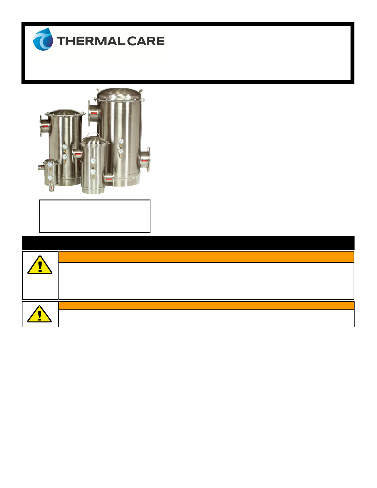
SF Series Screen Filter
OWNER’S MANUAL
Table of Contents
Safety Considerations..……………………………………….. 1
Receiving & Installation…...…….……………...…………… 2
Filter Operation, Maintenance, & Storage………. 2
Torque Recommendations…..……………………………… 3
Information Concerning Water Hammer…………….. 4
Limited Warranty……………………………………………….. 4
Spare Parts……………….…………………………………………. 5
Optional Equipment……………………………………………. 6
Ensure all appropriate personnel read owner’s manual prior to installation and/or operation of filter. Failure to
comply with instructions and safety precautions could lead to personal injury or product damage. Please call
(847) 966-2636 and ask to speak with one of our customer service representatives if there are any questions.
GENERAL WARNING
Serial # _______________
The Serial # is located on the top of the
outlet flange or pipe.
Always wear Personal Protective Equipment (PPE) - Eye protection, Ear protection, gloves, and protective footwear.
CAUTION

Page 2 of 6
1. Inspect filter to ensure there is no damage from transit.
2. Confirm all dust plugs/flange protectors (inlet, outlet, gauge ports, etc.) are removed.
3. Locate serial number on top of outlet flange or pipe (see diagrams below) and record in the box on page 1.
4. Position the filter into the piping system using the red arrows to indicate flow path.
5. All filters with a side inlet and a bottom foot ring must be placed on a firm supporting surface. DO NOT suspend the filter by the
inlet and outlet connections. All filters with vertical inlet piping must be plumbed into properly supported piping.
6. Installation of isolation valves on both the inlet and outlet sides of the filter is recommended to isolate the filter during maintenance.
7. Install a valve on the drainage port located at the bottom of the filter body (see diagram below). The valve must be plumbed to
atmosphere and the flush line should not have any elevation or be piped to a pressurized line.
8. Ensure pressure gauges (sold separately) are installed in the gauge ports located on the filter body (see diagram below). These gauges
will allow you to monitor the pressure differential across the screen.
9. Review all safety considerations from Section I. to determine if they have all been addressed.
10. Ensure all filter openings are properly connected.
11. Ensure the lid is properly installed. See diagram below and Section IV. Torque Recommendations for instruction.
II. RECEIVING & INSTALLATION
III. FILTER OPERATION, MAINTENANCE, & STORAGE
Start up
Open the downstream valve, then slowly allow fluid to flow through the filter by opening the upstream valve.
Flushing
Periodically (depending on liquid quality) the debris that settles out at the bottom of the filter will need to be flushed out. Open the flush port
valve while the filter is in operation to flush out debris. Flow rate, pressure, and amount of debris determine how long the valve should be open
to flush the debris from the filter tank. It is the user’s discretion to determine the frequency that the valve should be opened.
Never allow debris to accumulate beyond the capacity of the reservoir.
Check gauges to ensure the internal pressure of the filter is relieved before removing the retaining bolts/clamp of lid.
CAUTION
Clamped Lid Operating Instructions:
To Close -
Align vertical slots in the lid assembly with
the pins inside the housing.
Lower the lid assembly until it can be
rotated.
Rotate the lid assembly clockwise to stop.
The head will drop into a locked position
and should be unable to be removed by
pulling straight up.
Install the V-Band clamp.
To Open -
Remove the V-Band clamp.
Using the handle on top of the head; pull
up and rotate the lid assembly counter-
clockwise until the head is free from the
locking pins.
Outlet
Serial # Stamped on Outlet Flange
Foot Ring
NPT Flush Port
Outlet Pressure
Gauge Port
Inlet Pressure
Gauge Port
Inlet
Conical Screen
Element
Page 3 of 6
Cleaning
A pressure differential of approximately 5-7 PSI from the clean condition indicates that the screen requires cleaning. Please note that you must
maintain an inlet pressure that is higher than the pressure differential to maintain flow.
Step 1: Check gauges to ensure the internal pressure of the filter is relieved before removing the retaining bolts/clamps of lid.
Step 2: Remove the lid of the SF Series Screen Filter.
Step 3: Lift the filter element (conical screen) out of the filter body.
Step 4: Carefully scrub down the filter element with a rigid nylon brush until all matter is loosened. Do not use a steel brush.
Step 5: Wash the filter element off with clean water. Do not use a pressure washer.
Step 6: Rinse gaskets and clean the inner-ring where the bottom of the filter element seals.
Step 7: Make sure the U-shaped gasket is fitted securely to the bottom of the filter element. Position the filter element into the body of the
filter.
Step 8: Make sure the filter head gasket is installed on the upper flange of the top of the housing. On V-Band models, the o-ring should be
seated completely in the head assembly. Position the filter lid back on the filter body. Tighten the lid following the Torque
Recommendations.
Storage (Not in Service)
When the filter is not in service, Thermal Care recommends the following to prevent premature deterioration of the filter housing and screen.
Isolate the filter to ensure no flow and release pressure.
Drain the filter body by opening the flush port. Remove the internal screen and gaskets, and thoroughly rinse them with clean fresh water.
Rinse out the inside of the filter body with clean fresh water. Remove any excess water.
The filter is not freeze protected. Proper freeze protection steps must be taken to ensure the filter will not be damaged if exposed to freez-
ing conditions.
1
2
3
4
5
6
7
8
Recommended
Torquing
Sequence
NEVER operate the filter unless all bolts are properly fastened. It is important to follow the torque recommendations as over-torquing may result
in premature failure of the bolt. When tightening the bolted lid, follow the recommended torque sequence above. Complete the torque se-
quence 2 times.
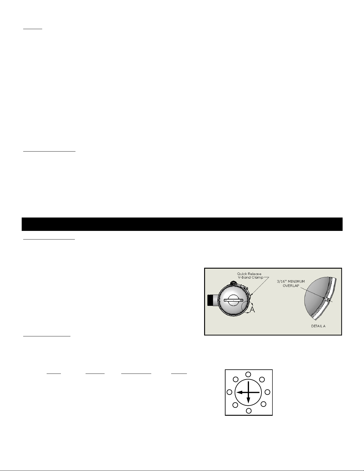
BAND CLAMP MODELS:
The over-center latch clamp is used on the band clamp models and is installed by placing the clamp around the filter, latching the T-bolt with the
receiver, then pushing the latch handle towards the filter body until the safety catch engages. The over-center clamp does not require
adjustment to be installed and removed. The lock nut is set at the factory for proper clamp compression and normally requires no initial field
adjustment. Minor adjustments may be necessary over time. When tightening
the lock nut, ensure that the clamp is compressing the o-ring to seal joint while
not creating an excessive amount of latch handle closing force. When the clamp
is closed, there should be a minimum overlap of 3/16” between the clamp inside
diameter and the outside diameters of both the lid and housing flanges.
(see diagram)
BOLTED LID MODELS:
The bolted lid Filters require that the attachment bolts be tightened sufficiently to make a complete seal without damaging the bolts or the filter
head. Bolts, nuts and washers are used to attach the heads to these filters. The size and recommended torque of the bolt is dependent on the
filter size. The following table shows the bolt size and torque rating for each filter.
Model Bolt Size TorqueBolt Quantity
4” Bolted (3/8”-16) 15 to 25 ft. lbs.10
6” (1/2”-13) 45 to 55 ft. lbs.10
8” (1/2”-13) 45 to 55 ft. lbs.15
10” (5/8”-11) 80 to 100 ft. lbs.20
IV. TORQUE RECOMMENDATIONS

Page 4 of 6
WHAT IS WATER HAMMER?
Water hammer is a phenomenon that can occur in fluid systems with long pipes between the fluid source and the outlet. The term itself refers to
the sound made when water hammer occurs which resembles banging a hammer on a long pipe. Water hammer is a rapid change of pressure
caused by a rapid change in velocity. When the velocity is changed a pressure wave that travels at the speed of sound is initiated and travels in
the upstream direction until it reaches some stationary energy level, like a reservoir. A rarefaction wave (at the pressure of the water source)
then travels downstream at the same speed. If the flow has been shut off down stream the pressure wave impacts the blockage and the pressure
in the entire system is raised very quickly.
WHAT CAUSES WATER HAMMER?
Any action that can cause a rapid change in the velocity of the flow can set off a water hammer - closing a downstream valve, pipe fracture, pump
stoppage, etc. The critical time for which a valve may be closed depends on the length of piping between the valve and the source reservoir. The
longer the distance the slower the valve may be shut to cause a water hammer. Typically for short lengths of pipe (below 500 ft) the critical time
is less than 1/10 second.
WHAT CAN WATER HAMMER DO?
Pressure spikes from water hammer can raise fluid pressures to very high values (in excess of 1000 PSI depending on the situation). Such
pressure spikes can result in mechanical failures such as broken valves, pipes, filters, joints, etc. Water hammer does not have to occur fully to
raise the pressure. A partial hammer can occur that raises the pressure to a certain percentage of the theoretical maximum. The SF Series Screen
Filter is rated to an absolute maximum pressure of 150 PSI for bolted lid models, 125 PSI for band clamp lid models. A water hammer pressure
spike that raises the pressure higher than the maximum rated pressure may result in filter damage.
WHAT CAN I DO TO PREVENT WATER HAMMER?
There are precautions that can be taken to prevent or decrease the effect of water hammer. A pressure relief valve that leads to a surge tank or
accumulator may protect other key components from water hammer. A close adherence to operational policies will also help prevent valves or
pumps from being accidentally shut off thereby causing a water hammer. A close examination of a system will inform you of potential hazards.
V. INFORMATION CONCERNING WATER HAMMER
VI. LIMITED WARRANTY
Thermal Care warrants its equipment to be free from defects in material and workmanship when used under recommended operating conditions.
Thermal Care's obligation is limited to repair or replacement (not adjustment or maintenance), F.O.B. the factory of any parts supplied by Thermal
Care within a period of twelve (12) months from the date of shipment to the original purchaser.
This warranty does not cover the cost of labor during overtime hours (after normal working hours or during weekends and holidays). Any cost
differential for overtime labor will be the responsibility of the customer. Thermal Care is not responsible for any sales, use, excise or other appli-
cable taxes associated with the replacement of parts under this warranty. This warranty will be voided when, in Thermal Care's opinion, the
equipment and/or system has been subject to misuse, negligence or operation in excess of recommended limits, including freezing, or has been
altered, and/or repaired without express factory authorization. If equipment is installed in hostile environments, unless such conditions were
specified at the time of purchase; or the serial number has been removed or defaced, this warranty shall not apply. All labor warranty coverage
provided by the Seller is based on normal ground mounted equipment with proper clearance and equipment access. The Buyer is responsible for
any additional costs associated with special rigging or access platforms required to perform the warranty work and/or any additional labor cost
associated with delays caused by the Buyer which prevent the Seller's service technician from performing their repair work in a proper timely
manner. This warranty is not transferable.
Under no circumstances shall Thermal Care be liable for loss of prospective or speculative profits, or special, indirect, incidental or consequential
damages.
Thermal Care must authorize all warranty service prior to work being performed and have a Thermal Care purchase order issued. All defective
parts become the property of Thermal Care and must be returned as advised by Thermal Care.
Thermal Care neither assumes, nor authorizes any person to assume for it, any liability not expressed in this warranty. There is an implied war-
ranty of merchantability and of fitness for that particular purpose; all other implied warranties, and any liability not based upon contract are
hereby disclaimed and excluded by this warranty. This warranty is part of the standard conditions and terms of sale of Thermal Care.
Page 5 of 6
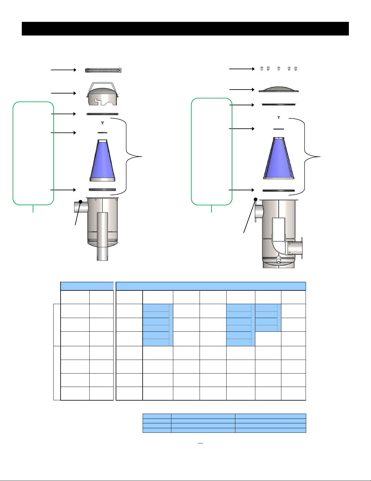
VII. SPARE PARTS
Model Inlet/Outlet Replacement Filter Disc Gasket Top Lid Clamp
Number Size &
Screen (a) Gasket Gasket Kit (b) Head or
Type *(EPDM) (EPDM) (EPDM) Fasteners
MLS-02-XXX 2" NPT
OR-02-2 GK-02-2 TH-02-2
MLS-03-XXX 3" NPT
OR-03-2 GK-03-2 TH-03-2
MLS-04B-XXX 4" Flanged
MLS-06-XXX 6" Flanged
MLS-08-XXX 8" Flanged
MLS-10-XXX 10" Flanged
Select proper O-Ring, Gasket Kit, and/or Top Head corresponding to serial number stamped on strainer outlet pipe/flange.
Strainer Model Serial No. Part Number Serial No. Part Number
MLS-2 0001-4999 OR-02 / GK-02 / TH-02 5000 & higher OR-02-2 / GK-02-2 / TH-02-2
MLS-3 0001-1999 OR-03 / GK-03 / TH-03 2000 & higher OR-03-2 / GK-03-2 / TH-03-2
MLS-4C 0500-1999 OR-04 / GK-04 2000 & higher OR-04-2 / GK-04-2
SCREEN OPTIONS:
"XXX" (in above part numbers) = MESH or PERFORATED SIZE of SCREEN
Complete Strainer and Replacement Screen orders must specify mesh or perforated size of screen. See catalogue for micron equivalent to mesh. Consult factory for assistance.
Screen Mesh Options: Standard Mesh - 16, 20, 30, 40, 50, 60, 80, 100, 120, 150, 200
Heavy-Duty Mesh - 24x110, 30x150, 40x200, 50x250 (Dutch-weave screens: heavier wire gauge, lower open area %)
Perforated Options: 1/4", 1/8", 1/16"
Select P/N from Table 1 below
Select from Table 1
TH-02
TH-03
GK-02
GK-03
GK-04
OR-03
OR-02
P/N: 2S-XXX
P/N: 3S-XXX
P/N: 4S-XXX
Head/O-Ring
Gasket
(EPDM)
Select P/N from Table 1 below
Table 1
STRAINER
REPLACEMENT PARTS
OR-04
OR-04-2
BAND CLAMP LID
BOLTED LID
GK-04-2
MLS-04C-XXX
4" Flanged
FG-02
DG-02
FG-03
DG-03
FG-04
DG-04
FG-08
DG-08
P/N: 4S-XXX
P/N: 6S-XXX
P/N: 8S-XXX
P/N: 10S-XXX
GK-04B
GK-06
FG-04
DG-04
FG-06
DG-06
TH-10
FASTENERS-10
FG-10
DG-10
BC-02
BC-03
BC-04
TH-04C
TH-04B
FASTENERS-04
HG-04
HG-06
HG-08
HG-10
TH-06
FASTENERS-06
GK-08
TH-08
FASTENERS-08
GK-10
Lid Clamp
*Top Head
*O-Ring Gasket
Disc Gasket
Filter Gasket
Replacement Screen
*Gasket Kit
Gaskets also
Available in
BUNA & VITON
*Part No. based on serial No. of
unit. Please have serial No.
available when ordering
Serial No. Location
SF Series Screen Filter - 2” thru 4C”
Fasteners
Top Head
Head Gasket
Disc Gasket
Filter Gasket
Replacement Screen
Gasket Kit
Gaskets also
Available in
BUNA & VITON
Serial No. Location
SF Series Screen Filter - 4B” thru 10”

Page 6 of 6
5680 W. Jarvis Ave.
Niles, IL 60714
Phone: (847) 966-2260
Fax: (847) 966-9358
OPTIONAL EQUIPMENT
Please note that the following equipment is not included with the purchase of the filter. Please call for information and pricing.
VIII. OPTIONAL EQUIPMENT
Pressure Differential Alarm Package (PDA)
Continuously monitors the pressure drop across the conical
screen.
Visual and audio alarm.
(1) dry output contact.
Automatic Timer Flush Package (ATF-EA-1.5)
Automatically purges particles that have gravitated down
into the debris reservoir at the base of the filter.
Dial in frequency and duration.
110V / 12VDC power supply included.
Full Cone Spray Nozzle Assembly Option
Rinse particles off the screen.
Decrease frequency of screen maintenance.
Other manuals for SF Series
2
Table of contents
Other Thermal Care Water Filtration System manuals


Popular Water Filtration System manuals by other brands

Axeon
Axeon SOLO I quick start guide

Intewa
Intewa SEPAMAT F 20 Installation and user manual

Hydor
Hydor BLUWAVE 05 user manual

Lectranator Systems
Lectranator Systems CRISTAL MAGIC CM3-1 Installation & operation manual

Bestway
Bestway FLOWCLEAR 58271 owner's manual

SpectraPure
SpectraPure Eliminator 90 Installation and operating manual


