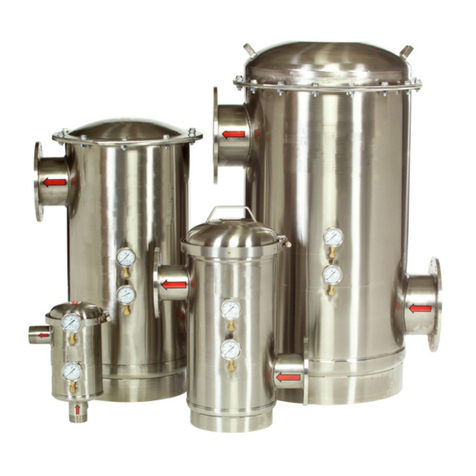
Thermal Care SF Series User manual


Page1of7
Serial #
The Serial # is located on the top of the
outlet flange or pipe.
1.DONOTEXCEEDTHEMAXIMUMRATEDPRESSUREORTEMPERATUREOFTHESFSTRAINER.Refertodecalslocatedon
thestrainer.
2.Undernocondionsshouldthestrainerlidorpressuregaugesberemovedwhilethestrainerispressurized.
3. Allstrainerswithasideinletandaboomfootringmustbeplacedonafirmsupporngsurface.DONOTsuspendthe
strainerbytheinletandoutletconnecons.Allstrainerswithvercalinletpipingmustbeplumbedintoproperly
supportedpiping.
4. UnitswithdamagedormissingpartsshouldNEVERbeoperated.ContactThermalCarePartsat847‐966‐8560for
replacementparts.
5. Back‐flowprevenondevicesshouldbeinstalledupstreamoftheinletanddownstreamoftheoutletofthestrainerto
preventbackfloworvacuumeffectsthatcanbedamagingtothestrainer.
6. Pressurereliefvalvesofasufficientsizeandvolumeshouldbeinstalledupstreamoftheinletanddownstreamofthe
outletofthestrainer.Theyshouldbesetsothesystemneverexceedsthemaximumratedpressure.Failuretoinstall
reliefvalvescouldleadtopersonalinjuryorproductdamage.
I. SAFETY CONSIDERATIONS
OWNER’S MANUAL
TableofContents
SafetyConsideraons..………………………………………..1
Receiving&Installaon…...…….……………...……………2
StrainerOperaon,Maintenance,&Storage……….2
TorqueRecommendaons…..………………………………3
InformaonConcerningWaterHammer……………..4
SpareParts……………….………………………………………….5
OponalEquipment…………………………………………….6
GENERAL WARNING
Ensureallappropriatepersonnelreadowner’smanualpriortoinstallaonand/oroperaonofstrainer.Failureto
complywithinstruconsandsafetyprecauonscouldleadtopersonalinjuryorproductdamage.Pleasecall
847‐966‐2636andasktospeakwithoneofourcustomerservicerepresentavesifthereareanyquesons.
CAUTION
PersonalProtecveEquipment(PPE)‐eyeprotecon,earprotecon,gloves,andprotecvefootwear‐mustbe
wornwhenoperangandservicingthestrainer.

Page2of7
1.Inspectstrainertoensurethereisnodamagefromtransit.
2.Confirmalldustplugs/flangeprotectors(inlet,outlet,gaugeports,etc.)areremoved.
3.Locateserialnumberontopofoutletflangeorpipe(seediagramsbelow)andrecordintheboxonpage1.
4.Posionthestrainerintothepipingsystemusingtheredarrowstoindicateflowpath.
5.Allstrainerswithasideinletandaboomfootringmustbeplacedonafirmsupporngsurface.DONOTsuspendthestrainerbytheinlet
andoutletconnecons.Allstrainerswithvercalinletpipingmustbeplumbedintoproperlysupportedpiping.
6.Installaonofisolaonvalvesonboththeinletandoutletsidesofthestrainerisrecommendedtoisolatethestrainerduringmaintenance.
7.Installavalveonthedrainageportlocatedattheboomofthestrainerbody(seediagrambelow).Thevalvemustbeplumbedto
atmosphereandtheflushlineshouldnothaveanyelevaonorbepipedtoapressurizedline.Ensureflushlineisplumbedtoprevent
operatorfromcontactwithflushwater.
8.Installpressuregauges(soldseparately)inthegaugeportslocatedonthestrainerbody(seediagrambelow)toallowmonitoringthe
pressuredifferenalacrossthescreen.
9.ReviewallsafetyconsideraonsfromSeconI.todetermineiftheyhaveallbeenaddressed.Reviewproceduresforsafeoperaonspecific
toyourapplicaon.
10.Ensureallstrainerportsareproperlyconnected.
11.Ensurethelidisproperlyinstalled.SeediagrambelowandSeconIV.TorqueRecommendaonsforinstrucons.
12.Thestrainerisnotfreezeprotected.Properfreezeproteconmethodsmustbeulizedtoensurethestrainerwillnotbedamagedifex‐
posedtofreezingcondions.
II. RECEIVING & INSTALLATION
III. STRAINER OPERATION, MAINTENANCE, & STORAGE
StartUp
Openthedownstreamvalve,thenslowlyallowfluidtoflowthroughthestrainerbyopeningtheupstreamvalve.
Flushing
Periodically(dependingonliquidquality)thedebristhatselesattheboomofthestrainerwillneedtobeflushedout.Opentheflushport
valvewhilethestrainerisinoperaontoflushoutdebris.Flowrate,pressure,andamountofdebrisdeterminehowlongthevalveshouldbe
opentoflushthedebrisfromthestrainertank.Itistheuser’sdiscreontodeterminethefrequencythatthevalveshouldbeopened.
Neverallowdebristoaccumulatebeyondthecapacityofthereservoir.
ClampedLidOperangInstrucons:
ToClose‐
Alignvercalslotsinthelidassemblywith
thepinsinsidethehousing.
Lowerthelidassemblyunlitcanbe
rotated.
Rotatethelidassemblyclockwisetostop.
Theheadwilldropintoalockedposion
andshouldbeunabletoberemovedby
pullingstraightup.
InstalltheV‐Bandclamp.
ToOpen‐
RemovetheV‐Bandclamp.
Usingthehandleontopofthehead;pull
upandrotatethelidassemblycounter‐
clockwiseunltheheadisfreefromthe
lockingpins.
Serial # Stamped
On Outlet Pipe
CAUTION
Theinternalpressureofthestrainermustberelievedtozerobeforeremovingtheretainingbolts/clampofthelid.

Page3of7
Cleaning
Apressuredifferenalofapproximately5‐7PSIfromthecleancondionindicatesthatthescreenrequirescleaning.
1.Removestrainerfromservicebyshungoffsystemvalvestoensurenofloworpressure.
2.Checkgaugestoensuretheinternalpressureofthestrainerisrelievedbeforeremovingtheretainingbolts/clampoflid.
3.Openflushportvalvetodrainfluidfromstrainerandrelievestrainerpressure.
4.Openairreliefvalvetobreakvacuumforfasterdrainingandtorelieveanyremainingstrainerpressure.
5.Removethelidofthestrainer.
6.Lithestrainerelement(conicalscreen)outofthestrainerbody.
7.Carefullyscrubdownthestrainerelementwitharigidnylonbrushunlallmaerisloosened.Do not use a steel brush.
8.Washthestrainerelementoffwithcleanwater.Do not use a pressure washer.
9.Rinsegasketsandcleantheinner‐ringwheretheboomofthestrainerelementseals.
10.FittheU‐shapedgasketsecurelytotheboomofthestrainerelement.Posionstrainerelementintothestrainerbody.
11.Fitthestrainerheadgasketontotheupperflangeofthetopofthehousing.Onclampmodels,theO‐ringshouldbe
seatedcompletelyintheheadassembly.FollowinstruconsinTorqueRecommendaons(Sect.IV).
12.Ensureflushportvalveandairreliefvalveareinclosedposionbeforereturningstrainertoservice.
Storage(NotinService)
Forstorageorextendeddownmefollowthesestepstopreventprematuredeterioraonofthestrainerhousingandscreen
Isolatethestrainertoensurenoflowandreleasepressure.
Drainthestrainerbodybyopeningtheflushport.Removetheinternalscreenandgaskets;rinsewithcleanfreshwater.Rinseouttheinside
ofthestrainerbodywithcleanfreshwaterandremoveanyexcesswater.Replaceallcomponentssecurelywhencompletelydry.
BAND CLAMP MODELS:
Theover‐centerlatchclampisusedtosecurethelidtothehousingonthestrainer‐clampmodels.Replacementclampsareshipped
withthelocknutnotpre‐setandmustbeadjusteduponinstallaon.Undernocondionsshouldthestrainerlidorpressuregaugesbe
removedwhilethestrainerispressurized.Clampinstallaoninstrucons:EnsureO‐Ringisproperlyinstalledonthelid.Placethelidonthe
strainerhousing,alignpinswithslotsinthelid,andtwisttolockintoplace.Placetheclamparoundtheflarededgesofthehousingandlid.
LatchtheT‐boltwiththereceiver.Pushthelatchhandle
towardsthestrainerbodyunlthesafetycatchengages.
AdjustthelocknutunltheclampInnerRetainerfits
securelyandisfullyengagedaroundtheflarededgesof
thelidandhousingflange.Theengagementcanbe
inspectedattheseparaongapsoftheInnerRetainer
andshouldhaveaminimumof3/16”overlap(see
diagram).Reclipsafetywarningtagtotheclamp.
BOLTED LID MODELS:
Theboltedlidstrainersrequirethattheaachmentboltsbeghtenedsufficientlytomakeacompletesealwithoutdamagingtheboltsorthe
strainerhead.Bolts,nutsandwashersareusedtoaachtheheadstothesestrainers.Thesizeandrecommendedtorqueoftheboltisdependent
onthestrainersize.Thefollowingtableshowstheboltsizeandtorquerangforeachstrainer.
NEVERoperatethestrainerunlessallboltsareproperlyfastened.Itisimportanttofollowthetorquerecommendaonsasover‐torqueingmay
resultinprematurefailureofthebolt.Tightenandtorqueboltsinanopposingpair“star”paernaccordingtoASMEPCC‐1‐2019Guidelinesfor
PressureBoundaryBoltedFlangeJointAssemblyorMIL‐HDBK‐60ThreadedFastenersTighteningtoProperTension.
IV. TORQUE RECOMMENDATIONS
Domeof
StrainerLid
3/16”
Overlap
BandClamp
Flangeof
StrainerLid
ModelBoltSizeTorque
4”Bolted(3/8”‐16)15to25.lbs.
6”(1/2”‐13)45to55.lbs.
8”(1/2”‐13)45to55.lbs.
10”/12”/14”(5/8”‐11)80to100.lbs.
BoltQuanty
10
10
16
20

Page4of7
WHAT IS WATER HAMMER?
Waterhammerisaphenomenonthatcanoccurinfluidsystemswithlongpipesbetweenthefluidsourceandtheoutlet.Thetermitselfrefersto
thesoundmadewhenwaterhammeroccurswhichresemblesbangingahammeronalongpipe.Waterhammerisarapidchangeofpressure
causedbyarapidchangeinvelocity.Whenthevelocityischangedapressurewavethattravelsatthespeedofsoundisiniatedandtravelsin
theupstreamdireconunlitreachessomestaonaryenergylevel,likeareservoir.Ararefaconwave(atthepressureofthewatersource)
thentravelsdownstreamatthesamespeed.Iftheflowhasbeenshutoffdownstreamthepressurewaveimpactstheblockageandthepressure
intheenresystemisraisedveryquickly.
WHAT CAUSES WATER HAMMER?
Anyaconthatcancausearapidchangeinthevelocityoftheflowcansetoffawaterhammer‐closingadownstreamvalve,pipefracture,pump
stoppage,etc.Thecricalmeforwhichavalvemaybecloseddependsonthelengthofpipingbetweenthevalveandthesourcereservoir.The
longerthedistance,thegreaterthemerequiredtoshutthevalvesafely.Typicallyforshortlengthsofpipe(below500)thecricalmeisless
than1/10second.
WHAT CAN WATER HAMMER DO?
Pressurespikesfromwaterhammercanraisefluidpressurestoveryhighvalues(inexcessof1000PSIdependingonthesituaon).Suchpressure
spikescanresultinmechanicalfailuressuchasbrokenvalves,pipes,strainers,joints,etc.Waterhammerdoesnothavetooccurfullytoraisethe
pressure.Aparalhammercanoccurthatraisesthepressuretoacertainpercentageofthetheorecalmaximum.TheSFStrainerisratedtoan
absolutemaximumpressureof150PSIforboltedlidmodels,125PSIforbandclamplidmodels.Awaterhammerpressurespikethatraisesthe
pressurehigherthanthemaximumratedpressuremayresultinstrainerdamage.
WHAT CAN I DO TO PREVENT WATER HAMMER?
Thereareprecauonsthatcanbetakentopreventordecreasetheeffectofwaterhammer.Apressurereliefvalvethatleadstoasurgetankor
accumulatormayprotectotherkeycomponentsfromwaterhammer.Acloseadherencetooperaonalpolicieswillalsohelppreventvalvesor
pumpsfrombeingaccidentallyshutofftherebycausingawaterhammer.Acloseexaminaonofasystemwillinformyouofpotenalhazards.
V. INFORMATION CONCERNING WATER HAMMER

Page5of7
VI. SPARE PARTS
*Top Head with
Air Relief Port
*O-Ring Gasket
Disc Gasket
Filter Gasket
Replacement Screen
*Gasket Kit
Gaskets also
Available in
BUNA & VITON
*Part No. based on serial No. of
unit. Please have serial No.
available when ordering.
SF Series Strainer - 2” thru 4C”
Fasteners
Top Head with
Air Relief Port
Head Gasket
Disc Gasket
Filter Gasket
Replacement Screen
Gasket Kit
Gaskets also
Available in
BUNA & VITON
Serial No. Location
SF Series Strainer - 4B” thru 14”
Lid Clamp
*O-Ring Gasket
Disc Gasket
Filter Gasket
Replacement Screen
*Gasket Kit
Gaskets also
Available in
BUNA & VITON
*Part No. based on serial No. of
unit. Please have serial No.
available when ordering.
Serial No. Location
Inlet/Outlet Replacement Disc Gasket Top Lid Clamp
Size & Screen (a) Gasket Kit (b) Head or
Type *(EPDM) (EPDM) Fasteners
2" NPT
OR-02-2 GK-02-2 TH-02-2
3" NPT
OR-03-2 GK-03-2 TH-03-2
4" Flanged
P/N:
4S-XXX HG-04 DG-04 GK-04B TH-04B
FASTENERS-04
6" Flanged
P/N:
6S-XXX HG-06 DG-06 GK-06 TH-06
FASTENERS-06
8" Flanged
P/N:
8S-XXX HG-08 DG-08 GK-08 TH-08
FASTENERS-08
10" Flanged
P/N:
10S-XXX HG-10 DG-10 GK-10 TH-10
FASTENERS-10
12" Flanged
P/N:
12S-XXX HG-12 DG-12 GK-12 TH-12
FASTENERS-12
14" Flanged
P/N:
14S-XXX HG-14 DG-14 GK-14 TH-14
FASTENERS-14
Table 1
REPLACEMENT PARTS NOTES:
Select O-Ring, Gasket Kit, and/or Top Head corresponding to serial number stamped on strainer outlet pipe/flange.
(a) Replacement Screen includes: Screen, Filter Gasket
Model Serial No. Serial No.
(U-Gasket, bottom of screen), & Disc Gasket (top of screen). MLS-2 0001-4999 5000 & higher
(b) Gasket Kit includes complete set for Strainer: MLS-3 0001-1999 2000 & higher
(1) Head Gasket or O-Ring, (1) Filter Gasket, & (1) Disc Gasket. MLS-4C 0500-1999 2000 & higher
Complete Filter and Replacement Screen orders must specify mesh or perforated size of screen. See catalog for micron equivalent to mesh.
Screen Mesh Options: Standard Mesh - 16, 20, 30, 40, 50, 60, 80, 100, 120, 150, 200
Heavy-Duty Mesh - 24x110, 30x150, 40x200, 50x250 (Dutch-weave screens: heavier wire gauge, lower open area %)
Perforated Options: 1/4", 1/8", 1/16"
FG-04
OR-02 / GK-02 / TH-02
OR-03 / GK-03 / TH-03
OR-04 / GK-04
Part Number
OR-02-2 / GK-02-2 / TH-02-2
OR-03-2 / GK-03-2 / TH-03-2
OR-04-2 / GK-04-2
Part Number
BAND CLAMP LID
BOLTED LID
GK-04-2
4" Flanged
OR-02
DG-03
DG-04
Select P/N from Table 1
FG-06
GK-02
GK-03
GK-04
FG-08
FG-10
FG-12
FG-14
BC-04
Gasket
(EPDM)
Select P/N from Table 1
OR-03
TH-02
TH-03
Filter
Gasket
(EPDM)
FG-02
FG-03
FG-04 TH-04C
SCREEN OPTIONS: "XXX"
(in above part numbers)
= MESH or PERFORATED SIZE of SCREEN
STRAINER
P/N:
2S-XXX
P/N:
3S-XXX
P/N:
4S-XXX
DG-02
REPLACEMENT PARTS
OR-04
Model
Number
OR-04-2
BC-02
Select from Table 1
Head/O-Ring
BC-03
MLS-02-XXX
MLS-03-XXX
MLS-04C-XXX
MLS-04B-XXX
MLS-06-XXX
MLS-08-XXX
MLS-10-XXX
MLS-12-XXX
MLS-14-XXX

Page6of7
OPTIONAL EQUIPMENT
Please note that the following equipment is not included with the purchase of the strainer. Please contact Thermal Care Sales at
847-966-2260 for information and pricing.
VII. OPTIONAL EQUIPMENT
PressureDifferenalAlarmPackageOverview(PDA2)
Thepressuredifferenalalarmpackageconnuallymonitorsanddisplaysthestrainer’sinletand
outletdifferenalpressure.Whenthestrainerelement(conicalstrainerbasket)becomessignifi‐
cantlyclogged,thepressuredifferenalswitch‐gaugewilltriggeranaudiblesirenandavisualflash‐
ingalarmlight.Thesealarmsareintendedtoalertmaintenancepersonnelthatthestrainerelement
mustberemovedandcleaned(seeyourSFStrainerOwner’sManualforcompletestrainerelement
cleaninginstrucons).
Features
ConnuouslymonitorstheDifferenalPressureacrosstheconicalscreen
AudibleandVisualAlarm
(1)dryoutputcontact

Page7of7
OPTIONAL EQUIPMENT
Please note that the following equipment is not included with the purchase of the strainer. Please contact Thermal Care Sales at
847-966-2260 for information and pricing.
VII. OPTIONAL EQUIPMENT (continued)
AutomacTimerFlushPackage(ATF‐EA‐1.5)
TheATF2isanautomatedflushvalvethatisdesignedforusewiththeSFStrainer.Ithasadigitalmer
thatallowstheoperatortosetthefrequencyandduraonofvalveopeninginordertoallowmoreeffec‐
veandefficientflushingofthecollecteddebrisfromthestrainer.
ControlBox:ThedigitalmerislocatedinsideaNEMA4enclosurethatincludesanAutoandManual
Valvefunconswitch.
BallValve/Actuator:Thevalvebodyhasa316SSballinsideaUVmodified,glass‐filledNylonhousing.The
actuatorhashightorquemotorgearsandsolidstatecomponentsforincreaseddurabilityandmainte‐
nancefreeperformancecontainedinsideaNEMA6Penclosure.
Features
Purgesparclesfromstraineratuser‐definedintervals
Adjustableflushfrequencyandduraon
Manualflushcontrolswitchwithindicator
Stainlesssteelballvalvedesignedfordirtywateruse

Other manuals for SF Series
2
Table of contents
Other Thermal Care Water Filtration System manuals
Popular Water Filtration System manuals by other brands

KineticoPRO
KineticoPRO NSC-120 owner's manual

Pentair
Pentair PRF-RO Installation and maintenance manual

AquaScape
AquaScape Ultraklean 2000 Instructions & maintenance
Wayde King Water Filtration
Wayde King Water Filtration Platinum Series owner's manual

Pond Boss
Pond Boss PonDuett 3000 operating manual
IMI
IMI norgren F64C Installation & maintenance instructions
