Thermasis HYDRA PLUS User manual

HYDRA PLUS
Installation and
User Manual
2021/R02/Hydra Plus_Micronova
Dear Customer,
Thank you for having chosen our product.
To allow for optimal operation and for you to enjoy the warmth and sense of wellbeing that
the fire can convey in your home, we advise you to read this manual carefully before starting
up the product for the first time.
CARE OF THE MANUAL AND HOW TO CONSULT IT
Take care of this manual and keep it in an easily accessible place.
Should the manual be misplaced or ruined, request a copy from your retailer or directly from
the authorised Technical Assistance Department.

1 INTRODUCTION
HYDRA PLUS is a welded steel hydro-pellet stove with all hydraulic and safety accessories
packed inside the cabinet. Main features and advantages of HYDRA PLUS are as follows:
Automatic ignition
PID control, output regulation
High heat resistant ceramic sightglass with auto cleaning system
Double layer door design with additional tempered glass frontial door
Packed with all accessories suc as;
-Circulation pump with frequency modulation
-7 lt expansion tank
-Safety valve
-Automatic air relief valve
-Water pressure switch for low pressure protection
-Air pressure switch
Safety against back burning
Exhaust fan speed modulation
Burning pot made of special stainless steel
Manually activated cleaning system in smoke pipes
Auto switch-off when there is no fuel
HYDRA PLUS is delivered in one single wooden package with all external cabinets assembed,
no additional assembly is requried
2 WARRANTY CONDITIONS
THE MANUFACTURER guarantees the product, with the exception of elements subject to
normal wear (listed below), for a period of 2 (two) years;
Starting from date of start-up, which is proven by a commissioning document that
contains the name of the seller and the date when the sale / first start-up took place
If there is no service/commissioning report, standard guarantee period starts with
the date when the sale took place.
The term ‘warranty’ refers to the (free-of-charge) replacement or repairs of parts
acknowledged to be faulty due to manufacturing defects.
Furthermore, in order for the guarantee to be valid, the product must be installed and
calibrated by qualified personnel. Installations that do not meet the current standards,
improper use and lack of maintenance as expected by the manufacturer, void the product
warranty. The warranty is valid on the condition that the instructions and warnings
contained in this manual are observed, and therefore the product is used correctly.
The replacement of the entire system or the repair of one of its components does not
extend the warranty period, and the original expiry date remains unchanged.

EXCLUSIONS FROM WARRANTY
Parts subject to normal wear such as gaskets, ceramic glass, cast iron grilles, vermiculite
boards, fire bricks, fire stone burners, handles and electric cables, knobs, all parts which can
be removed from the firebox, are excluded from the warranty
Any part that may be faulty as a result of negligence or careless use, incorrect maintenance
or installation that does not comply with the manufacturer's instructions (see the relative
chapters in user manuals of each product).
The warranty will be rendered null and void in the event of damage caused by tampering,
atmospheric agents, natural disasters, vandalism, electrical discharges, fire, faults/defects in
the electric and/or hydraulic system, and maintenance not being performed at all or as
indicated by the manufacturer instructions
Non-regular electrical supplies, and electrical power cuts off too often, can cause severe
damage on control system, sensors and actuators of the products carrying those
components. We recommend installing 230 V 50 Hz AC voltage regulator for those products.
Also installing a UPS for pumps can protect system from electrical cut-offs causing over
heating of water.
The warranty does not cover malfunctions and/or damage to the appliance that arise due to
the following causes:
Damage caused during internal transportation and/or handling
All parts that develop faults due to negligence or improper use, incorrect
maintenance, installation that does not comply with the manufacturer’s instructions
(always refer to the installation manual provided with the product)
Improper overheating of the equipment, use of fuels not conforming to the types and
quantities indicated in the instructions provided
Further damage caused by incorrect user interventions in an attempt to fix the initial
fault
Worsening of the damage caused by the user continuing to operate the appliance
even after the fault has been noticed.
In case of a boiler/hydro stove, any corrosion, incrustations or breakages caused by
water flow, condensation, lack of water in the system, mud or limescale deposits
Inefficiency of chimneys, flues or parts of the system affecting the appliance.
Failure to have the annual product maintenance performed by an authorised
technician or qualified personnel will result in the loss of the warranty.
Save for the legal or regulatory limits, the warranty does not cover the containment
of atmospheric and acoustic pollution.
THE MANUFACTURER declines all liability for any damage which may be caused, directly or
indirectly, to persons, animals or objects as a consequence of non compliance with any
provision specified in the manual, especially warnings regarding installation, use and
maintenance of the appliance.
SPARE PARTS
Only use original spare parts. The retailer or service centre can provide all necessary
information regarding spare parts. We do not recommend waiting for the parts to get worn
out before having them replaced. It is important to perform regular maintenance.

The Manufacturer declines all liability if the product and any other accessory is used
improperly or modified without authorisation. All parts must be replaced with original spare
parts. Warranty cover is valid if the product is installed and tested by a qualified installer,
according to the detailed instructions provided in the instruction manual supplied with the
product. The term ‘warranty’ refers to the (free-of-charge) replacement or repairs of parts
acknowledged to be faulty due to manufacturing defects.
3 SAFETY WARNINGS
•Installation, electrical connection, functional verification and maintenance must only be
performed by qualified or authorised personnel. Install the product in accordance with
all the local and national laws and standards applicable in the relative region.
•Only use fuel recommended in this manual. Do not put any fuel other than wood pellets
in the hopper. Keep cover of the fuel hopper always closed.
•Do not place laundry on the product to dry. Any clothes or similar objects including the
fuel must be kept at a safe distance from the product.
•Any type of tampering or unauthorised replacement with non-original spare parts could
be hazardous for the operator's safety and relieve the producer/re-seller from any civil
and criminal liability.
•Most of the surfaces of the product are very hot (door, handle, glass, smoke outlet pipes,
etc.). Avoid contact with these parts unless adequate protective clothing is worn or
appropriate means are used, such as heat protective gloves or cold handle type
operating systems. When opening the internal front door, always use the unique
apparatus attached at back side of the product. It is forbidden to operate the product
with the door open or the glass broken.
•THE PRODUCT MUST BE POWERED BY A SYSTEM THAT IS EQUIPPED WITH AN
EFFECTIVE EARTH SYSTEM.
•Switch the product off in the event of a fault or malfunctioning.
•Accumulated unburned pellets in the burner (fire pot) after each "failed start-up" must
be removed before starting up again.
•Do not wash the product with water. The water could get inside the unit and damage the
electrical insulation and cause electric shocks.
•INSTALL THE PRODUCT IN ROOMS THAT ARE ADEQUATELY PROTECTED AGAINST FIRE
AND EQUIPPED WITH ALL THE UTILITIES SUCH AS SUPPLIES (AIR AND ELECTRICITY) AND
SMOKE OUTLETS.
•If a fire breaks out inside the chimney, switch the appliance off, disconnect it from the
mains and do not open the door. Then contact the competent authorities.
•If the ignition system is faulty, do not force ignition with flammable materials.
•Special maintenance must only be performed by authorised and qualified personnel.
DANGER –Risk of electric shock
Switch off the system before performing work on the boiler.
THIS APPLIANCE MUST BE EARTHED !
NOTICE –First operation
•It is quite normal to smell water vapour contained in the special coating of combuston unit
of the product. This smell will be go out through chimney after a few hours of first
opeation, and it should not be considered as a product defect.
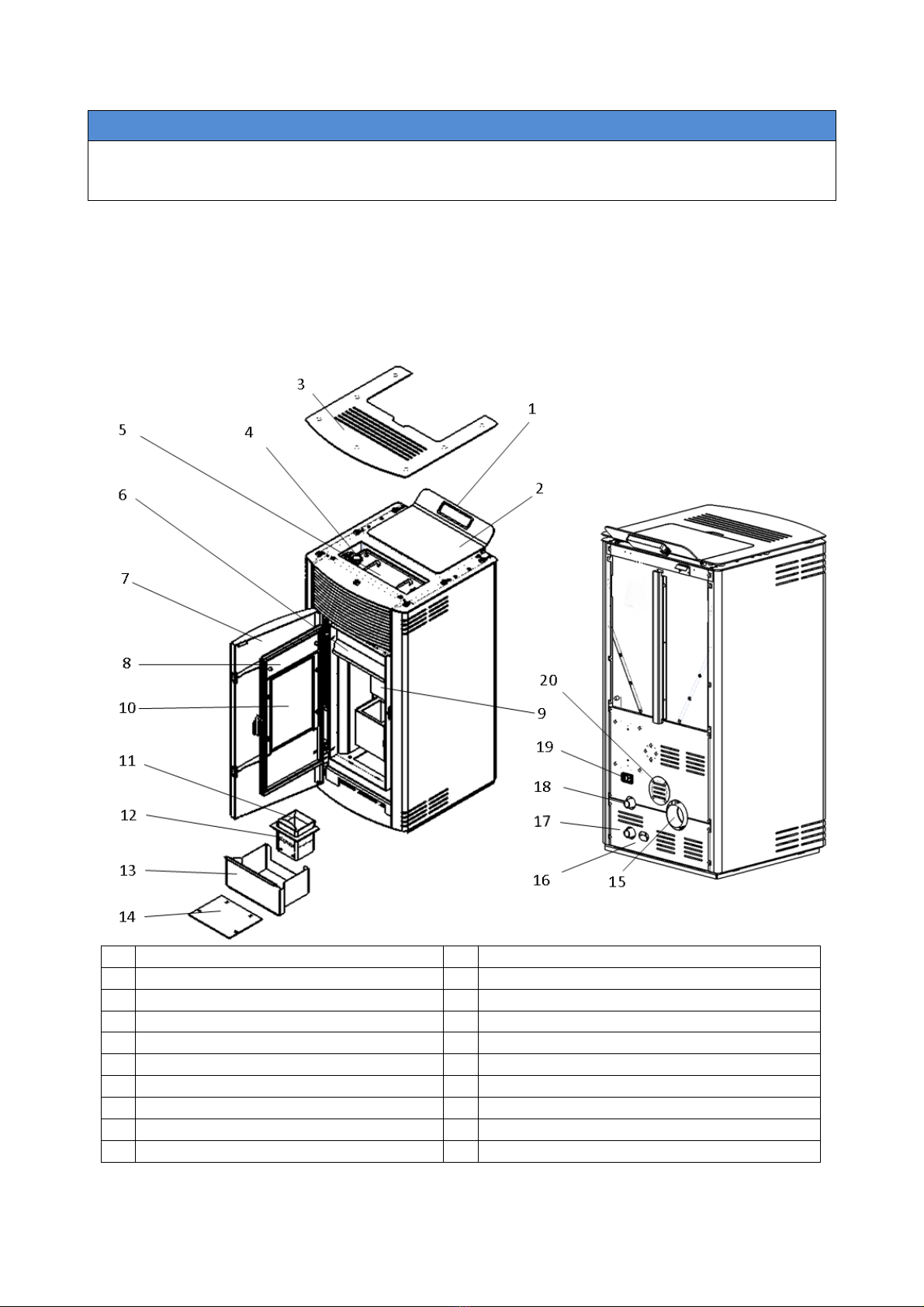
4 MAIN PARTS AND SPECIFICATIONS
For end users:
1
User interface and command display
11
Burning pot upper ring
2
Fuel loading cover
12
Burning pot
3
Top panel
13
Ash tray
4
Smoke pipes cleaning knobs
14
Smoke-hood cleaning cover
5
Combustion unit upper insulation panel
15
Flue outlet
6
Glass cleaning mechanism
16
Safet valve outlet
7
External door
17
Hot water outlet
8
Internal door
18
Cold water inlet
9
Protection panels in combustion unit
19
Main switch of boiler
10
Ceramic glass / inspection window
20
Optional inlet for combustio air (room –seal)
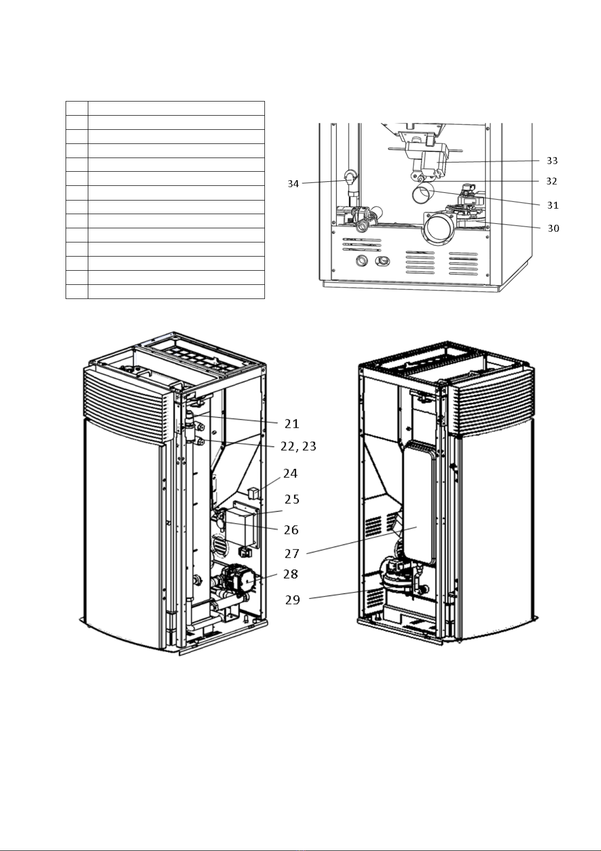
For installers / service staff:
21
Air discharge valve
22
Sensor pocket (boiler thermostat)
23
Sensor pocket (safety limiter)
24
Safety limiter
25
Control board
26
Air pressure switch
27
Expansion tank
28
Circulation pump
29
Flexible connection for exp tank
30
Suction fan
31
Combustion air entrance
32
İgnitor
33
Pellet feeding motor
34
Water pressure switch

5 BEFORE INSTALLATION
5.1. Fuels
Pellets must comply with Class A1 or A2 according to EN 14961-2
Diameter (mm)
6 ± 1
Length (mm)
Max 40
Moisture (w)
≤ 10%
Ash (w)
≤ 1,5%
Net Calorific Value (kWh/kg)
≥ 4.4
To guarantee combustion without problems, pellets must be kept in a dry place. Poor quality
pellets or others that do not comply with that specified previously compromises the operation
of your product and can therefore render the warranty and product liability null and void.
5.2. Room selection / operating environment
The product must be installed in a suitable place for regularly operation and routine
maintenance. The site must be:
Compliant for proper operation.
Equipped with an adequate smoke expulsion system. The product must be connected to
a chimney or an internal/external vertical duct that complies with the regulations in force.
The product must be positioned in such a way that the electrical socket is accessible.
Equipped with ventilation intake from outside.
Equipped with 230V 50 Hz power supply with an EC compliant earth system.
Operating environment must ensure the following regulations unless any local regulation
in force request different conditions
The volume of the room where the product is installed should be no less than 15 m3. Air
must enter through permanent openings made in the walls (near the product) that reach
outwards with a minimum section of 100 cm2for Vega 12/16, and 150 cm2for Vega 24
without the protective grille. In the case of ducting, up to 3.5 linear meters, increase the
cross-section by about 5%, whereas for longer ducts, increase it by 15%. These openings
(air inlets) must be made in such a way that it is impossible for them to be obstructed in
any way. The opening must be positioned in the lower part of an outer wall, preferably
opposite to that in which the smoke evacuation duct is located.
Air can also be drawn from adjacent rooms to the one that is to be ventilated, provided
they have an external air inlet and are not used as a bedroom or bathroom or where there
is a fire hazard, such as: garages, timber storerooms, warehouses of flammable
materials, observing under all circumstances the the provisions of all the applicable
standards in force.

The adjacent room from which air is
taken must not have a low pressure
compared to the exterior due to a
counter draught caused by the
presence in that room of another
appliance in use or of a suction
device.
NOTICE
The product cannot be installed (except for sealed operation appliances with external ducted
combustion air intake):
•in bedrooms or bathrooms;
•in rooms where there are liquid fuel appliances with continuous or intermittent operation
that draw the combustion air from the room they are installed in;
•in rooms where there are B-type gas heating appliances, with or without domestic hot
water production and interconnecting rooms;
•where another heating appliance is installed without an independent air flow.
It is recommended to install the stove detached from any walls and/or furniture, with a
minimum clearance to allow effective aeration of the appliance and a good distribution of heat
in the room. Observe the distances from flammable or heat-sensitive objects (sofas, furniture,
wood panelling, etc..) as specified below. If particularly delicate objects are present, such as
furniture, curtains or sofas, increase the stove clearance accordingly.
A
B
If the floor is made of combustible material, it is recommended to use protection made of non-
combustible material (steel, glass...) that also protects the front from falling combusted
material during cleaning operations.
The appliance must be installed on a floor with adequate load capacity. If the existing
construction does not meet this requirement, one must take appropriate measures (for
example a load distribution plate).
WARNING
Heat-sensitive or flammable objects cannot be placed near the product. Keep such objects
at a minimum distance of 80 cm from the outermost point of the product.
Leave minimum 80 cm free space in front of the stove for loading, and cleaning of
combustion unit.
REFERENCES
FLAMMABLE OBJECTS
NON-FLAMMABLE
A
200 mm
100 mm
B
200 mm
100 mm

5.3. Connection of the smoke exhaust duct
When making the hole for the passage of the
smoke discharge pipe, one must take into
account the possible presence of flammable
materials. If the hole must be made through a
wooden wall or thermolabile material, the
INSTALLER MUST first of all use the
appropriate wall fitting (minimum diameter 13
cm) and suitably insulate the pipe of the
product that passes through it using adequate
insulating materials (1.3 - 5 cm thick with
minimum thermal conductivity 0.07 W/m°K).
The same minimum distance must be applied
if the pipe of the product must pass through
vertical or horizontal sections near the
thermolabile wall. It is recommended to use an
insulated double-wall pipe in external sections
in order to prevent condensation from forming.
Note that the combustion chamber works in
negative pressure.
WARNING
Always use pipes and fittings with appropriate seals that guarantee tightness.
NOTICE
The following conditions must be complied with when connecting the appliance to the chimney:
The smoke duct must be at least category T200 (or higher if required by the smoke
temperature of the appliance) and P1-type (airtight).
All 90° angles (max. 3) in the smoke exhaust duct must be preferably fitted with the
relative T-fittings with inspection hole.
It is strictly forbidden to fit a mesh at the end of the exhaust pipe as it could cause the
product to malfunction (due to clogging).
It is forbidden to use counter-sloping pipes.
The horizontal section of the smoke duct must not be longer than 2-3 m.
It is also recommended not to exceed 6 metres in length with the pipe Ø 80 mm.
The smoke duct must not cross rooms in which it is forbidden to install combustion
appliances.
5.4. Connection to the chimney
The chimney must comply with the following requirements:
• Be waterproof and thermally insulated.
• Be made of suitable materials that resist mechanical stress over time, heat, the effects of the
combustion products and any possible condensation.
• Have a vertical set-up with deviations from the axis of no more than 45° and free of
bottlenecks.
• Must be suitable for the specific operating conditions of the product and have the CE marking
(EN1856-1, EN1443).
• Must be adequately sized for the draught/smoke expulsion requirements that are necessary for
the product to operate correctly (EN13384-1).
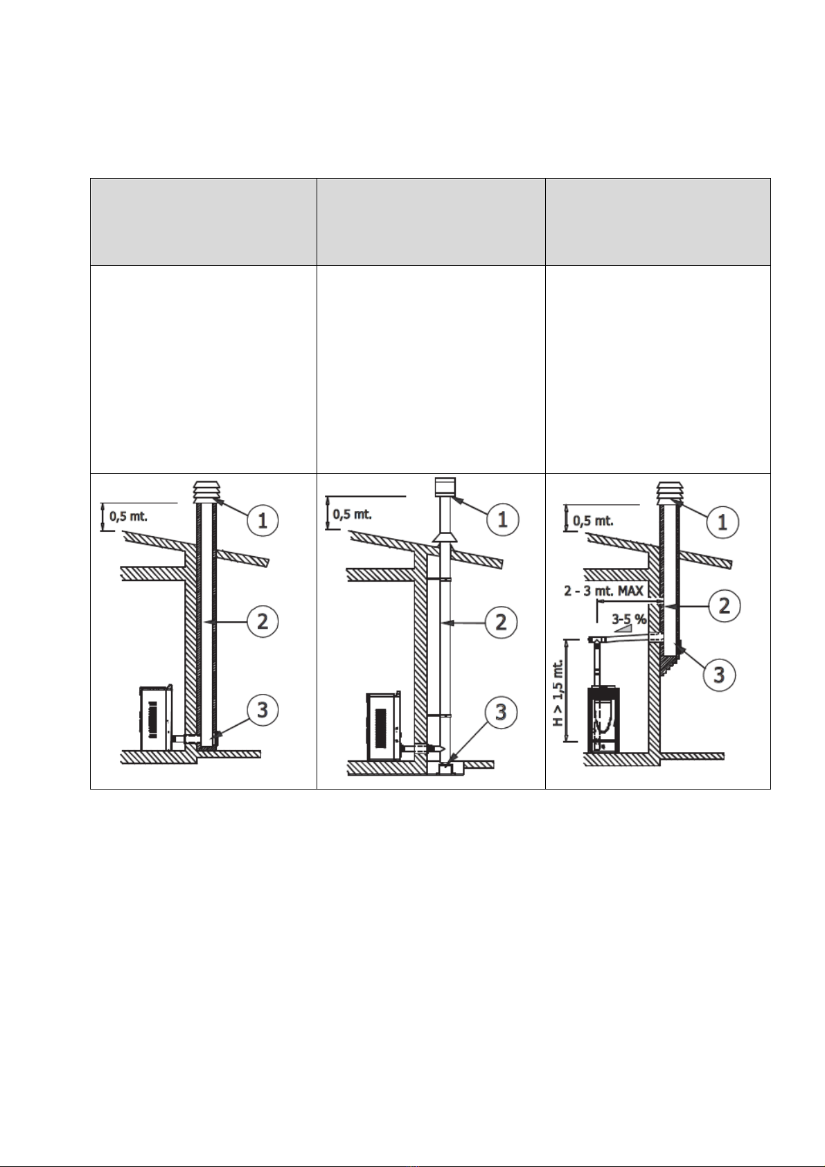
• The internal section is preferably circular.
• In the case of a pre-existing product that has been used, it must be cleaned.
• The chimney must not be shared with other appliances.
1) Windproof chimney pot, 2) Chimney 3) Inspection hole
CONNECTION TO THE
CHIMNEY
CONNECTION TO AN
EXTERNAL DUCT WITH AN
INSULATED OR DOUBLE-
WALL PIPE
CONNECTION TO THE
CHIMNEY
The chimney's internal
dimensions must not exceed
20x20 cm or 20 cm diameter;
in the event of bigger sizes or
bad chimney conditions (e.g.
cracks, poor insulation, etc.), it
is advisable to fit a stainless
steel pipe of suitable diameter
throughout the length of the
chimney right to the top.
The minimum internal
dimensions of the external duct
must be 10x10 cm or 10 cm
in diameter and must not
exceed 20x20 cm or 20 cm in
diameter. Only stainless steel
insulated (double-wall) pipes
must be used, which are
smooth on the inside and fixed
to the wall. Flexible stainless
steel pipes must not be used.
The connection between the
product and the chimney or the
smoke duct must not have an
inclination that is less than 3%
in the horizontal sections,
which must have a maximum
overall length of 2/3 m. The
vertical section between one
T-fitting and another (angle)
must not be less than 1.5 m.

5.4. Chimney stack
The chimney stack is a device fitted on the top of
the chimney that is designed to aid dispersion of
the products of combustion in the atmosphere.
Chimney stack must comply with the following
requirements:
it must have an internal section and shape the
same as the flue (A);
it must have a useful outlet section (B) of not
less than twice that of the flue (A);
the part of the chimney that emerges from
the roof or remains in contact with the outside
(e.g. in the case of a flat roof), must be
covered with brick or tile elements and in any
case well insulated;
it must be built in such a way as to prevent
the penetration of rain, snow and foreign
matter into the flue and to ensure that in the
event of winds from all directions and angle,
discharge of the combustion products is
assured (chimney stack with down-draught
cowl).

6 INSTALLATION AND PLUMBING
6.1. Unpacking
The stove is supplied complete with all its electrical and mechanical components and factory-
tested. Open the package and cut the strip that fastens the stove to the pallet.
If possible, unpack the stove near the chosen place of installation. Set the stove in the pre-
selected place, making sure this complies with the requirements. The stove body or unit must
always be kept in a vertical position when handled and moved by using carts only. Pay
particular attention that its door and its glass are protected from knocks that might
compromise their integrity. There are four rubber bases supplied with the stove. Screw them
into nuts fitted bottom level of the stove, and balance the stove by adjusting those rubber
bases up and down.
The materials that make up the packaging are neither toxic nor harmful, and so require no
particular disposal measures. After removing the packaging make sure that the stove is
complete and not damaged. If in doubt contact the dealer.
6.2. Hydraulic connections
This appliance has been designed to heat not only the immediate surrounding environment,
but also water for a hot-water type heating system. When the appliance is operating regularly
it produces hot water at a temperature that is necessarily below boiling point and a heating
system must therefore be designed that is suited to the characteristics of the appliance.
The installer must connect the appliance to the water system as shown in following diagram.
This set-up allows:
an instant check of filling or operating pressure of the system (MANOMETER WITH
SCALE 0 ÷ 6 BAR) (2)
the stove to be moved slightly for maintenance or cleaning purposes, without
disconnecting it from the water system (HOSES) (4)
The original system filling water and any topping-up water must always be filtered (using
synthetic or metal mesh filters with a filtration rating of no less than 50 microns) to prevent
sludge from forming and triggering deposit induced corrosion (STRAINER/FILTER) (5)

the stove to be disconnected from the water system without having to empty either the
stove boiler or the actual system (BALL VALVES) (3)
the appliance to be disconnected quickly without subjecting the connecting pipes to
stress (3-PIECE PIPE UNION) (1)
The safety valve must be connected using a hose without shut-off devices, which could
obstruct the free flow of fluid under pressure.Check that any kinks in the hoses will not allow
air locks or pockets to form or obstruct the free flow of water.
NOTICE
Before connecting the appliance, flush the heating system through to eliminate any residues (oil,
swarf, drops of weld material, hemp, rust) inside the pipework, which could otherwise damage
the appliance or cause malfunction. Insulate the connecting pipework adequately to prevent
heat loss and the formation of condensation. Under no circumstances light the appliance unless
the water circuit is completely filled with water.
The expansion tank installed inside the appliance is only sufficient to compensate the water in
the appliance and up to a MAX. of 20 lt of water in the system; the part of the system
corresponding to this quantity must be near the appliance and run relatively straight.
Installation of a suitably sized additional expansion tank is however recommended to
compensate for the quantity of water present in the heating system. The correct size of the
expansion tank must be calculated by a qualified heating plumber. As an example, the design
calculations for an expansion tank are given below, taking into consideration the following:
cold temperature of fluid 15°C
maximum working temperature of fluid 90°C
difference in level between additional expansion tank and relief valve (3 bar) equal to
or less than 1.5 m
pre-filling pressure of the expansion tank 2 bar.
The capacity of the closed expansion tank required by a heating system with such characteristics
can be calculated with the following formula:
Vv= Vox 0.16
Vv= volume of the expansion tank in l
Vo= water content of the system in l
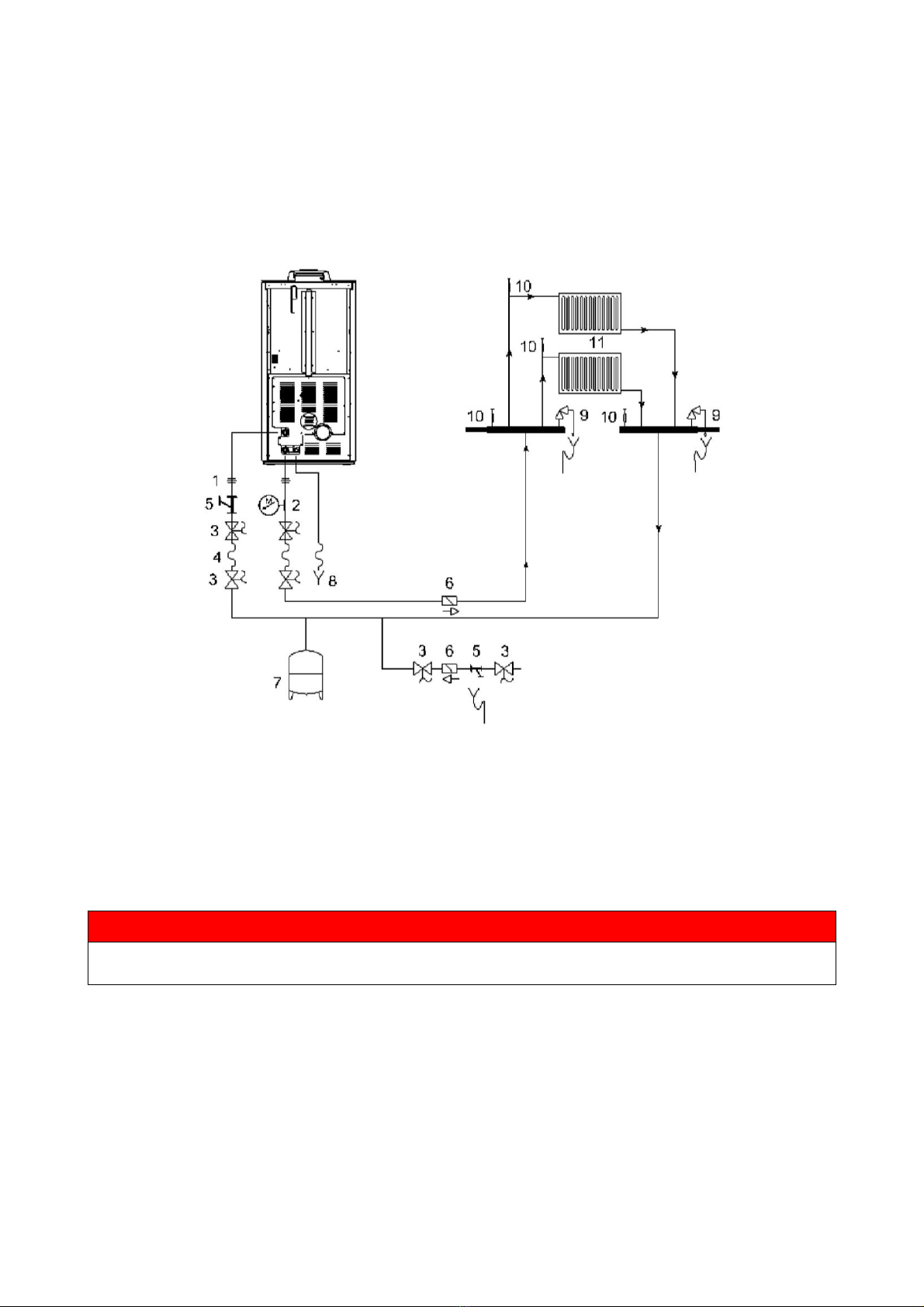
1
Three piece pipe union
7
Expansion tank
2
Manometer
8
Drain
3
Ball valve
9
Safety valve
4
Hose
10
Air relief valve
5
Strainer (filter)
11
Radiator
6
Check valve
6.3. System filling
Fill the water heating system when the appliance is shut down. Under no circumstances light
the appliance if the boiler is not full of water. Filling must be carried out slowly so that air
bubbles can get out via the purposely placed outlets on the heating system. In closed circuit
heating systems the loading pressure of the system when cold and the expansion tank
preloading pressure must be the same.
WARNING
Do not mix the heating water with antifreeze or anticorrosion substances in the wrong
concentrations! It can damage the seals and cause the onset of noise during operation.
To fill the system, the boiler is fitted with a tap, with a check valve, to load the heating system
manually. During this operation, any air in the system is released via the air valve located in
the upper part of the boiler.
Open the radiator, and boiler air discharge valves;
Gradually open the system filling tap making sure that any automatic air valves
installed on the system work properly;
Close the radiator air valves as soon as water starts to come out;
On the system pressure gauge check that the pressure reaches a value of
approximately 1 bar;

Close the system loading tap and then bleed air again via the radiator air valves; and
check tightness of all connections;
After having started the boiler for the first time and heated up the system, stop the
pumps and repeat the air bleeding operations;
Let the system cool down and if needed take the water pressure back to 1 bar. The
water pressure in the heating system - when the system is cold - must be no less than
1 bar; if under this value, act on the system filling tap. The operation must be carried
out when the system is cold. The system pressure gauge enables to monitor the
pressure in the circuit.
Auto air discharge valve of the stove is reached after removing top and of right hand
side panel:
6.4. Electrical connection
Electrical safety of the system is ensured only when it is properly connected to an efficient
earthing system made in compliance with the safety standards in force. Gas, water or heating
systems pipes are not suitable as earth connections. Check if the electrical system is suitable
for the maximum power absorbed by the heating system, ensuring in particular that the
diameter of cables is appropriate for the power absorbed by the loads. The use of any
component that is powered by electricity entails compliance with some basic rules such as:
• do not touch the appliance with wet and/or damp body parts and/or bare feet;
• do not pull the electric cables;
• do not leave the appliance exposed to weathering (rain, sun, etc.);
• do not allow the appliance to be used by children or inexperienced persons.
Installation of the boiler accessory electrical components requires electrical
connection to a 230 V –50 Hz mains.
NOTICE
Electrical installation must be carried out by a qualified technician only.
Before performing connections or any operation on the electrical parts, always disconnect the
power supply and make sure it cannot be accidentally reconnected.
Please note that the boiler electrical power line must be fitted with a bipolar switch with a
contact gap greater than 3 mm, easy to access, in order to make any maintenance
operations quick and safe.
The power cable must be replaced by authorised technical personnel.
If the supply cord is damaged, it must be replaced by a special cord or assembly available
from the manufacturer or its service agent.
First connect the power cable to the stove and then
to a wall socket. The main switch at the side must
only be activated to switch the stove on; otherwise,
it is advisable to keep it off.
WARNING
It is recommended to disconnect the power cable when the stove is not used.
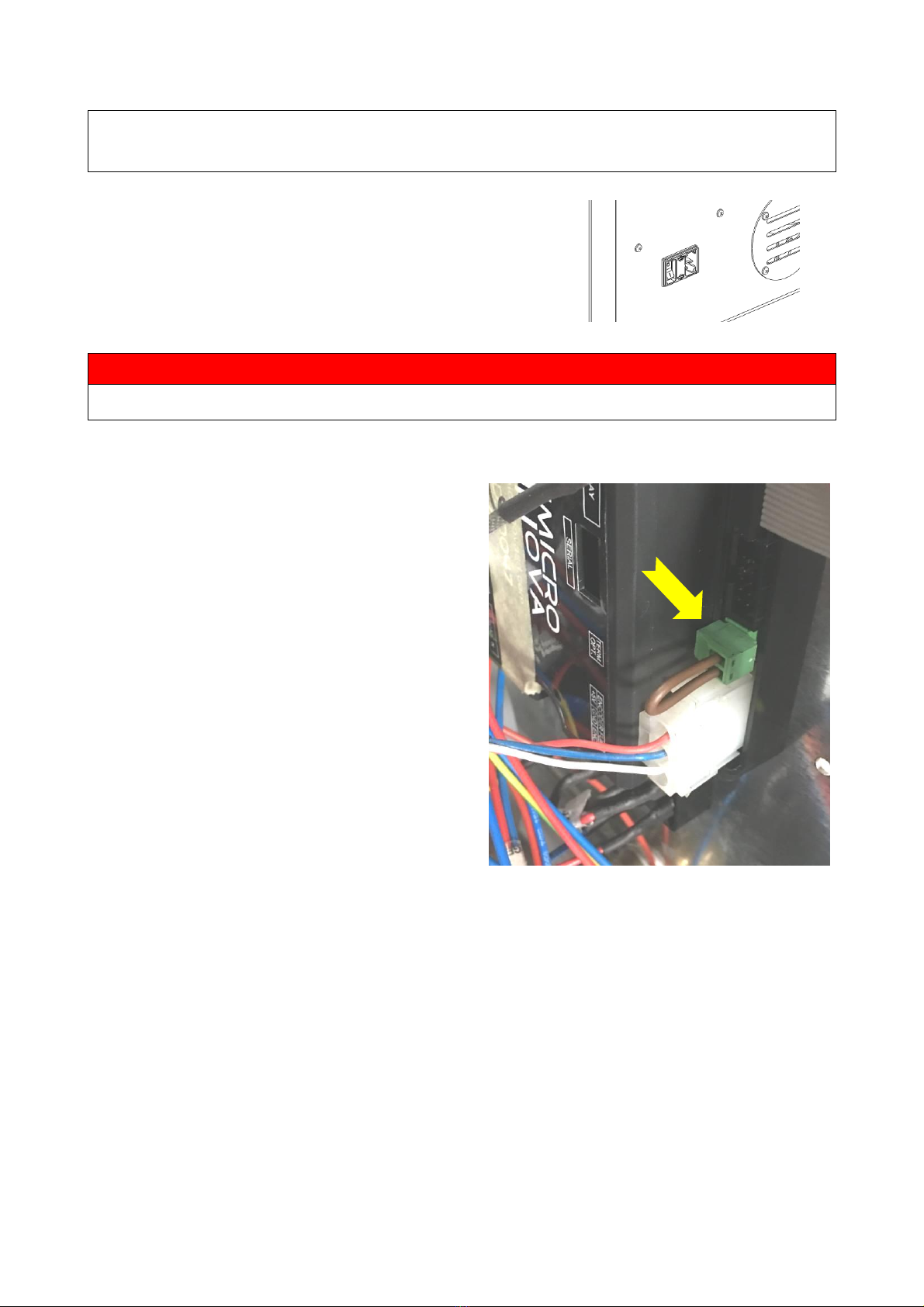
6.5. External room thermostat
The external thermostat can be used
to turn the combustion system on
and off. In this case the controller
ignores all internal temperature
thresholds and is operating
exclusively with the thermostat input.
To configure this option; connect
room thermostat wires into the ports
of green connector on board as seen
below

7 INITIAL START-UP
7.1. Before start-up
Check that the fire pot and its ring above are positioned correctly and rests properly on the
base. Fire pot ring fits into fire pot by its sides. Fire pot ring ensures all pellets will enter the
fire pot, protects burning pellets from moving out from the pot. So, it is very important to keep
that ring during stove operation.
Once the power cable is connected in the rear part of the stove, turn the switch to position (I).
To switch the stove on or off press ON/OFF button (4) on the control panel.
7.2. Loading the pellets
Fuel is loaded by lifting the cover on the upper part of the product. Slowly pour the pellets into
the hopper. Be careful as the cover could become very hot. No other type of fuel other than
pellets, in compliance with above-mentioned specifications, is to be inserted into the hopper.
WARNING
Do not allow sawdust to accumulate on the bottom of the hopper.
Do not leave leftover pellets on top of the stove –they could catch fire!
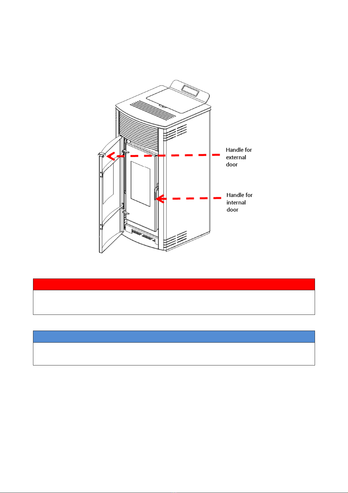
7.3. Opening and closing the door
First open external door via the handle on top right corner. Then, unhook the lock on the
internal door of the stove, as shown in the figure
WARNING
Internal door must be closed properly for the stove to work correctly.
Use suitable Personal Protective Equipment (e.g. gloves) to open the stove door.
NOTICE
Stove is equipped with a water pressure switch that protects the boiler from operation without
water inside. The minimum setting of pressure switch is 0,2 bars. That is why, your stove will
not be in operation, unless water pressure inside the hydraulic circuit is above 0,2 bars.
Table of contents
Popular Stove manuals by other brands

ROBENS
ROBENS FIREFLY instruction manual

Dean
Dean Hembury Slimline operating instructions

Harrie Leenders
Harrie Leenders HL2 Manual and installation instructions

EverHot
EverHot ElectricStove owner's manual

Harman Stove Company
Harman Stove Company P61A-2 owner's manual

Flame King
Flame King VT-505 Care, use and safety instructions


VARDE OVNE
VARDE OVNE Fuego 1 Installation and user guide

Brunton
Brunton Crux user manual

BRULA
BRULA CITY GRUNDI Maxi Assembly and operating instructions

Harman Stove Company
Harman Stove Company Accentra owner's guide

RIKA
RIKA LOOK Assembly manual

Vilpra Sauna
Vilpra Sauna Fornax VPR-14 Installation and operation manual