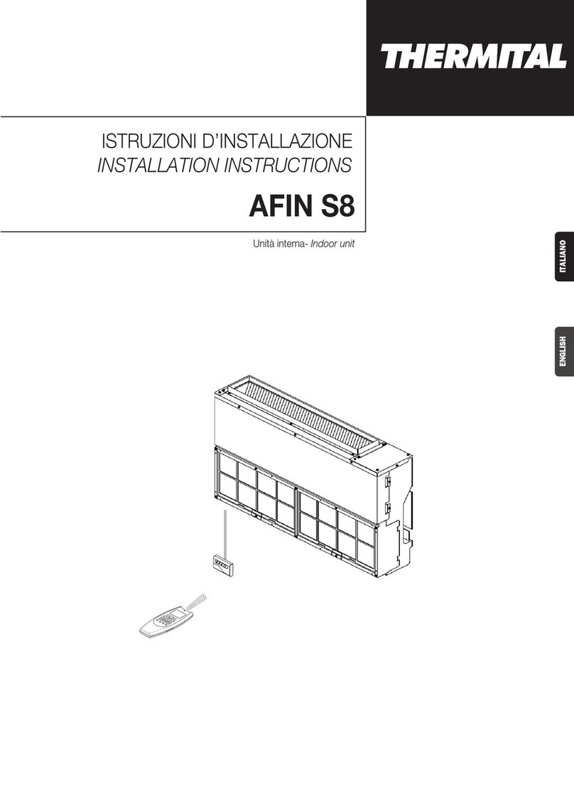
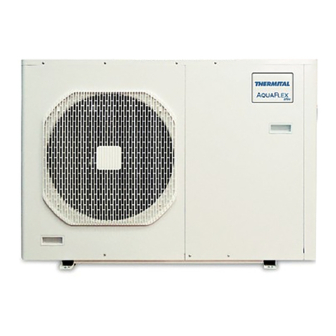
thermital AFIN AP S10 User manual

AFIN AP
ISTRUZIONI DI INSTALLAZIONE
IT
INSTALLATION INSTRUCTIONS
EN
Condizionatore d’aria Split System
Split system air conditioner
AFIN AP S10
AFIN AP S13

■Condizioni Massime in Raffreddamento
Temperatura esterna : 43°C B.S.
Temperatura interna: 32°C B.S. / 23°C B.U.
■Condizioni Minime in Raffreddamento
Temperatura esterna : –15°C B.S.
Temperatura interna: 10°C B.S. / 6°C B.U.
■Condizioni Massime in Riscaldamento
Temperatura esterna : 24°C B.S. / 18°C B.U.
Temperatura interna: 27°C B.S.
■Condizioni Minime in Riscaldamento
Temperatura esterna : –15°C B.S.
Temperatura interna: 5°C B.S.
LIMITI DI FUNZIONAMENTO
DICHIARAZIONE DI CONFORMITÀ
Questo prodotto è marcato in quanto conforme alle Direttive:
– Bassa Tensione n. 2014/35/UE (Standard: EN60335-2-40:2003 (incl. Corr.:2006) + A11:2004 + A12:2005 + A13:2012
+ A1:2006 + A2:2009 with EN 60335-1:2002 + A11:2004 + A1:2004 + A12:2006 + A2:2006 + A13:2008 + A14:2010
+ A15:2011).
– Compatibilità Elettromagnetica n. 2014/30/UE, 92/31 CEE e 93/68 CEE. (Standard: EN55014-1 (2006) + A1(2009) +
A2(2011), EN 55014-2 (1997) + A1(2001) + A2 (2008), EN 61000-3-2 (2006) + A1(2009) + A2(2009),
EN 61000-3-3 (2008)
– RoHS2 n.2011/65/UE.
– Regolamento (UE) n. 206/2012, del 6 marzo 2012, relativo alle specifiche per la progettazione ecocompatibile dei
condizionatori d’aria e dei ventilatori.
– Regolamento (UE) n. 626/2011, del 4 maggio 2011, relativo all’etichettatura indicante il consumo d’energia dei
condizionatori d’aria.
Questa dichiarazione sarà nulla nel caso di impiego diverso da quello dichiarato dal Fabbricante e/o di mancata
osservanza, anche solo parziale, delle istruzioni d’installazione e/o d’uso.
Combinazione Modelli:
VEDI CATALOGO
1.Cacciavite a lama
2.Cacciavite medio a
stella
3.Forbici spelafili
4.Metro
5.Livella
6.Punta fresa a tazza
7.Seghetto
8.Punta da trapano ø 8
19.Martello
10.Trapano
11.Tagliatubi a coltello
rotante
12.Flangiatubi a giogo per
attacco a cartella
13.Chiave dinamometrica
14.Chiavi fisse o a rullino
15.Sbavatore
16.Chiave esagonale
Attrezzi necessari per l’installazione (non forniti)
Alimentazione elettrica:
220 - 240 V ~ 50 Hz
REGOLAMENTO (UE) N. 517/2014 - F-GAS
L’unità contiene R410A, un gas fluorurato a effetto serra,
con potenziale di riscaldamento globale (GWP) = 2087,50.
Non disperdere R410A nell’ambiente.
GARANZIA
Il prodotto Tgode di una
garanzia convenzionale
(valida per Italia, Repubblica di San Marino, Città del
Vaticano), a partire dalla data di acquisto del prodotto stesso.
b
Conservare la documentazione di acquisto scalmente valida del prodotto da presentare all'Assistenza
Autorizzata al momento della richiesta dell'intervento in garanzia.
Trova l'Assistenza Autorizzata più vicina visitando il sito
www.thermital.it
Gentile tecnico,
ci complimentiamo con Lei per aver proposto un condizionatore d’aria split system AFIN AP, un prodotto moderno,
in grado di assicurarLe il massimo benessere per lungo tempo con elevata afdabilità, efcienza, qualità e sicurezza.
Con questo libretto desideriamo fornirLe le informazioni che riteniamo necessarie per una corretta e più facile
installazione dell'apparecchio senza voler togliere nulla alla Sua competenza e capacità tecnica.
Buon lavoro e rinnovati ringraziamenti.
T
2
ITALIANO

IMPORTANTE!
Leggere prima di iniziare l’installazione
Questo sistema di condizionamento deve seguire rigidi
standard di sicurezza e di funzionamento.
Per l’installatore o il personale di assistenza è molto
importante installare o riparare il sistema di modo che
quest’ultimo operi con sicurezza ed efficienza.
Per un’installazione sicura e un buon
funzionamento è necessario:
• Leggere attentamente questo manuale di istruzioni prima
di iniziare.
• Seguire tutte le istruzioni di installazione o riparazione
esattamente come mostrato.
• Osservare tutte le norme elettriche locali, statali e
nazionali.
• Fare molta attenzione a tutte le note di avvertimento e di
precauzione indicate in questo manuale.
• Per l’alimentazione dell’unità utilizzare una linea elettrica
dedicata.
AVVERTIMENTO
Questo simbolo si riferisce a pericolo o utilizzo improprio
che possono provocare lesioni o morte.
PRECAUZIONE
Questo simbolo si riferisce a pericolo o utilizzo improprio
che possono provocare lesioni, danni all’apparecchio o
all’abitazione.
Se necessario, chiedi aiuto
Queste istruzioni sono tutto quello che necessita
per la maggior parte delle tipologie di installazione e
manutenzione.
Nel caso in cui servisse aiuto per un particolare problema,
contattare i nostri punti di vendita/assistenza o il vostro
negoziante per ulteriori informazioni.
In caso di installazione errata
La ditta non è responsabile di un’errata installazione o
manutenzione qualora non vengano rispettate le istruzioni
di questo manuale.
PARTICOLARI PRECAUZIONI
• Durante l’installazione eseguire prima il collegamento
del circuito frigorifero e poi quello elettrico, procedere
in modo inverso nel caso di rimozione delle unità.
Quando è elettrico
LA SCARICA ELETTRICA PUÒ CAUSARE
LESIONI MOLTO GRAVI O LA MORTE. SOLO
ELETTRICISTI QUALIFICATI ED ESPERTI
POSSONO MANIPOLARE IL SISTEMA
ELETTRICO.
• Non alimentare l’unità finché tutti i cavi e i tubi non siano
completati o ricollegati e controllati, per assicurare le
messa a terra.
• In questo circuito elettrico vengono utilizzati voltaggi
elettrici altamente pericolosi. Fare riferimento allo schema
elettrico e a queste istruzioni durante il collegamento.
Collegamenti impropri e inadeguata messa a terra
possono causare lesioni accidentali o la morte.
• Eseguire la messa a terra dell’unità secondo le norme
elettriche locali.
• Il conduttore giallo/verde non può essere utilizzato per
collegamenti diversi dalla messa a terra.
• Fissare bene i cavi. Collegamenti inadeguati possono
causare surriscaldamento e un possibile incendio.
• I cavi elettrici non devono venire a contatto con i tubi
refrigeranti, il compressore o le parti mobili del ventilatore.
• Nel collegare l’alimentazione e le linee di controllo, non
usare cavi a più conduttori. Usare cavi separati per
ciascun tipo di linea.
Durante il trasporto
Fare attenzione nel sollevare e nello spostare le unità
interna ed esterna. È consigliabile farsi aiutare da qualcuno
e piegare le ginocchia quando si solleva per evitare strappi
alla schiena. Bordi affilati o sottili fogli di alluminio del
condizionatore potrebbero procurarvi dei tagli alle dita.
Durante l’installazione...
... A soffitto, a muro o a pavimento
Assicurarsi che siano abbastanza resistenti da reggere il
peso dell’unità. Potrebbe essere necessario costruire un
telaio in legno o metallo per provvedere a un supporto
maggiore.
... In un locale
Isolare accuratamente ogni tubazione nel locale per
prevenire formazione di condensa che potrebbe causare
gocciolamento e, di conseguenza, arrecare danni a muri
e pavimenti.
... In luoghi umidi o irregolari
Usare una base solida e rialzata dal terreno per predisporre
l’Unità Esterna.
Questo eviterà danni e vibrazioni anormali.
... In luoghi altamente ventilati
Ancorare saldamente l’unità esterna con bulloni e un telaio
in metallo. Provvedere a un adatto deflettore per l’aria.
... In luoghi soggetti a nevicate (per i condizionatori
pompa calore)
Installare l’Unità Esterna su una piattaforma più alta del
livello di accumulo della neve. Provvedere a un’apertura
di sfogo per la neve.
Collegando il circuito frigorifero
• Tenere le tubazioni più corte possibili.
• Usare il metodo di cartellatura per collegare i tubi.
• Oliare con olio anticongelante le superfici di contatto
della cartellatura e avvitare con le mani, quindi stringere
le connessioni utilizzando una chiave dinamometrica in
modo da ottenere un collegamento a buona tenuta.
• Verificare attentamente l’esistenza di eventuali perdite
prima della prova di funzionamento (test run).
NOTA:
A secondo del tipo di sistema, le tubazioni per liquidi o
gas possono essere sia piccole che grandi. Per evitare
confusione, parlando di tubazione refrigerante, sarà
specificato: tubo piccolo per liquido, grande per gas.
Durante le riparazioni
• Togliere tensione (dall’interruttore generale) prima di
aprire l’unità per controllare o riparare parti elettriche.
• Tenere lontano mani e vestiti da ogni parte mobile.
• Pulire dopo aver terminato il lavoro, controllando di non
aver lasciato scarti metallici o pezzi di cavo all’interno
dell’unità.
• Areare il locale durante l’installazione e la prova del
circuito refrigerante; assicurarsi inoltre che, una volta
completata l’installazione, non si verifichino perdite di
gas refrigerante poiché il contatto con fiamme o fonti di
calore può essere tossico e molto pericoloso.
AVVERTIMENTO
3ITALIANO

Scelta del luogo di installazione unità interna
EVITARE
• L’esposizione diretta al sole.
• La vicinanza a fonti di calore che possono danneggiare
la struttura dell’unità.
• La presenza di perdite di gas.
• La presenza di vapori d’olio (come in una cucina o vicino
a macchinari industriali) perché la contaminazione d’olio
può provocare malfunzionamento e può deformare
superfici e particolari in plastica dell’unità.
• Locali con piani di appoggio malfermi che possono
causare vibrazione, rumore o possibili perdite d’acqua.
• Luoghi dove l’unità e il telecomando possano essere
soggetti a spruzzi d’acqua o umidità eccessiva (es.
lavanderia).
• Di eseguire fori nelle zone dove si trovano parti elettriche
o impianti.
È PREFERIBILE
• Scegliere la posizione appropriata dalla quale ogni angolo
del locale possa essere uniformemente climatizzato.
• Verificare che il piano di appoggio sia sufficientemente
resistente da sostenere il peso dell’unità.
• Scegliere una posizione in modo che la distanza tra le
due unità sia la minore possibile.
• Scegliere la posizione più appropriata per assicurare
una buona ventilazione e spazi minimi di manutenzione
intorno all’unità.
Scelta del luogo di installazione unità esterna
EVITARE
• La vicinanza a fonti di calore o ad aree interessate da
espulsioni di aria calda.
• L’esposizione diretta al sole.
• Zone umide o soggette ad allagamenti e piano di
appoggio non livellato.
• Di eseguire fori nelle zone dove si trovano parti elettriche
o impianti.
È PREFERIBILE
• Scegliere aree possibilmente in ombra e leggermente
ventilate.
• Fissare l’unità alla base di appoggio per evitare vibrazioni.
(continua a pag. 8)
LIMITI SU LUNGHEZZA TUBI DI COLLEGAMENTO E DISLIVELLO
V. ISTRUZIONI DI INSTALLAZIONE UNITA’ ESTERNA
GAMMA E CONFORMITÀ
MODELLO CODICE
AFIN AP S13 20145478
AFIN AP S10 20145480
MATERIALE ADDIZIONALE PER L’INSTALLAZIONE (NON FORNITO)
• Tubo in rame ricotto e disossidato per refrigerazione per il collegamento tra le unità, ed isolato con polietilene espanso di spessore
min. 8 mm.
•
Tubo in PVC per scarico condensa (ø int. 18 mm) di lunghezza sufficiente a convogliare la condensa ad uno scarico esterno.
•
Olio refrigerante per connessioni a cartella (circa 30 g.)
•
Cavo elettrico: utilizzare cavi di rame isolato del tipo, sezione e lunghezza indicati nel paragrafo “COLLEGAMENTI ELETTRICI”
.
Modello Tubo piccolo Tubo grande
Diametro esterno Spessore minimo Diametro esterno Spessore minimo
AFIN AP S10 6,35 0,8 12,7 0,8 mm
AFIN AP S13 6,35 0,8 12,7 0,8 mm
CONTATTO IN INGRESSO ON/OFF (J11 - verde)
Lo stato di questo ingresso provoca le seguenti modalità
di funzionamento del sistema del sistema:
lContatto APERTO: sistema non in funzione (sempre
OFF) - I comandi provenienti dal controllo remoto
wireless sono ignorati.
lContatto CHIUSO: il sistema funziona secondo la
logica normale e in accordo con i comando provenienti
dal controllo remoto wireless.
CONTATTO DI ALLARME IN USCITA (J20 - rosso)
Questo connettore è collegato ad un contatto normalmente
aperto di un relè. Tale contatto si chiude ogni qualvolta
interviene una delle seguenti condizioni di allarme del
sistema:
lRAT danneggiato
lICT danneggiato
lCommunication error
lFault on outdoor unit
Nel caso si intervento di un allarme sui poli 1 e 3 del
connettore J20 sarà presente una tensione pari a 220
VAC-50Hz.
Carico elettrico massimo: 1 A - 240 V CA.
MATERIALE ADDIZIONALE PER L’INSTALLAZIONE (A CORREDO)
ALLARME
ON/OFF
4
ITALIANO

■Cooling Maximum conditions
Outdoor temperature : 43°C D.B.
Room temperature : 32°C D.B. / 23°C W.B.
■Cooling Minimum conditions
Outdoor temperature : –15°C D.B.
Room temperature : 10°C D.B. / 6°C W.B.
■Heating Maximum conditions
Outdoor temperature : 24°C D.B. / 18°C W.B.
Room temperature : 27°C D.B.
■Heating Minimum conditions
Outdoor temperature : –15°C D.B.
Room temperature : 5°C D.B.
OPERATING LIMITS
DECLARATION OF CONFORMITY
This product is marked as it satisfies Directives:
– Low voltage no. 2014/35/UE. (Standard: EN60335-2-40:2003 (incl. Corr.:2006) + A11:2004 + A12:2005 + A13:2012
+ A1:2006 + A2:2009 con EN 60335-1:2002 + A11:2004 + A1:2004 + A12:2006 + A2:2006 + A13:2008 + A14:2010
+ A15:2011).
– Electromagnetic compatibility no. 2014/30/UE, 92/31 EEC and 93/68 EEC. (Standard: EN55014-1 (2006) + A1(2009)
+ A2(2011), EN 55014-2 (1997) + A1(2001) + A2 (2008), EN 61000-3-2 (2006) + A1(2009) + A2(2009),
EN 61000-3-3 (2008)
– RoHS2 no.2011/65/EU.
– Regulation (EU) no. 206/2012, of 6 march 2012, concerning the specifications for ecodesign requirements of air
conditioners and fans.
– Regulation (EU) no. 626/2011, of 4 may 2011, concerning the labeling indicating the energy consumption of air
conditioners.
This declaration will become void in case of misuse and/or non observance though partial of manufacturer’s installation
and/or operating instructions.
Power Supply:
220 - 240 V ~ 50 Hz
1.Standard screwdriver
2.Phillips head screwdriver
3.Knife or wire stripper
4.Tape measure
5.Level
6.Sabre saw or key hole saw
7.Hacksaw
8. Core bits ø 8
19.Hammer
10.Drill
11.Tube cutter
12.Tube flaring tool
13.Torque wrench
14.Adjustable wrench
15.Reamer (for reburring)
16.Hex. key
Tools required for installation (not supplied) Model Combinations:
SEE
CATALOGUE
REGULATION (EU) No. 517/2014 - F-GAS
The unit contains R410A, a fluorinated greenhouse gas
with a global warming potential (GWP) of 2087.50. Do not
release R410A into the atmosphere.
Dear heating engineer,
we would like to congratulate you on having recommended a split system air conditioner AFIN AP: a modern product
that's capable of ensuring maximum comfort over time with a high degree of reliability, efciency, quality and safety.
While your technical skills and knowledge will certainly be more than sufcient, this booklet contains all the
information that we have deemed necessary for the device's correct and easy installation.
Please accept our thanks and our congratulations on your choice of product.
T
5ENGLISH

IMPORTANT!
Please read before installation
This air conditioning system meets strict safety and
operating standards.
For the installer or service person, it is important to
install or service the system so that it operates safely and
efficiently.
For safe installation and trouble-free
operation, you must:
• Carefully read this instruction booklet before beginning.
• Follow each installation or repair step exactly as shown.
• Observe all local, state and national electrical codes.
• Pay close attention to all warning and caution notices
given in this manual.
•The unit must be supplied with a dedicated electrical line.
WARNING
This symbol refers to a hazard or unsafe practice which
can result in severe personal injury or death.
CAUTION
This symbol refers to a hazard or unsafe practice which can
result in personal injury or product or property damage.
If necessary, get help
These instructions are all you need for most installation
sites and maintenance conditions.
If you require help for a special problem, contact our
sale/service outlet or your certified dealer for additional
instructions.
In case of improper installation
The manufacturer shall in no way be responsible for
improper installation or maintenance service, including
failure to follow the instructions in this document.
SPECIAL PRECAUTIONS
• During installation, connect before the refrigerant system
and then the wiring one; proceed in the reverse orden
when removing the units.
When wiring
ELECTRICAL SHOCK CAN CAUSE SEVERE
PERSONAL INJURY OR DEATH. ONLY A
QUALIFIED, EXPERIENCED ELECTRICIANS
SHOULD ATTEMPT TO WIRE THIS SYSTEM.
• Do not supply power to the unit until all wiring and tubing
are completed or reconnected and checked, to ensure
the grounding.
• Highly dangerous electrical voltages are used in this
system. Carefully refer to the wiring diagram and these
instructions when wiring.
Improper connections and inadequate grounding can
cause accidental injury and death.
• Ground the unit following local electrical codes.
• The Yellow/Green wire cannot be used for any connection
different from the ground connection.
• Connect all wiring tightly. Loose wiring may cause
overheating at connection points and a possible fire
hazard.
• Do not allow wiring to touch the refrigerant tubing,
compressor, or any moving parts of the fan.
• Do not use multi-core cable when wiring the power
supply and control lines. Use separate cables for each
type of line.
When transporting
Be careful when picking up and moving the indoor and
outdoor units. Get a partner to help, and bend your knees
when lifting to reduce strain on your back. Sharp edges
or thin aluminium fins on the air conditioner can cut your
fingers.
When installing...
... In a ceiling or wall
Make sure the ceiling/wall is strong enough to hold the
unit-weight. It may be necessary to build a strong wooden
or metal frame to provide added support.
... In a room
Properly insulate any tubing run inside a room to prevent
“sweating”, which can cause dripping and water damage
to walls and floors.
... In moist or uneven locations
Use a raised concrete base to provide a solid level
foundation for the outdoor unit.
This prevents damage and abnormal vibrations.
... In area with strong winds
Securely anchor the outdoor unit down with bolts and a
metal frame. Provide a suitable air baffle.
... In a snowy area (for heat pump-type systems)
Install the outdoor unit on a raised platform that is higher
than drifting snow. Provide snow vents.
When connecting refrigerant tubing
• Keep all tubing runs as short as possible.
• Use the flare method for connecting tubing.
• Apply refrigerant lubricant to the matching surfaces of
the flare and union tubes before connecting them; screw
by hand and then tighten the nut with a torque wrench
for a leak-free connection.
• Check carefully for leaks before starting the test run.
NOTE:
Depending on the system type, liquid and gas lines may
be either narrow or wide. Therefore, to avoid confusion,
the refrigerant tubing for your particular model is specified
as narrow tube for liquid, wide tube for gas.
When servicing
• Turn the power OFF at the main power board before
opening the unit to check or repair electrical parts and
wiring.
• Keep your fingers and clothing away from any moving
parts.
• Clean up the site after the work, remembering to check
that no metal scraps or bits of wiring have been left
inside the unit being serviced.
• Ventilate the room during the installation or testing the
refrigeration system; make sure that, after the installation,
no gas leaks are present, because this could produce
toxic gas and dangerous if in contact with flames or
heat-sources.
WARNING
6
ENGLISH

Installation site selection - Indoor unit
AVOID
• Direct sunlight.
• Nearby heat sources that may affect unit performance.
• Areas where leakage of flammable gas may be expected.
• Locations where large amounts of oil mist may occur
(such as in kitchen or near factory equipment) because
oil contamination can cause operation problems and may
deform plastic surfaces and parts of the unit.
• Unsteady locations that will cause noise or possible water
leakage.
• Locations where the indoor unit and the remote control
unit will be splashed with water or affected by dampness
or humidity (i.e. in laundries).
• To make holes in areas where electrical wiring or conduits
are located.
DO
• Select an appropriate position from which every corner of
the room can be uniformily cooled.
• Select a sufficiently strong location to support the weight
of the unit.
• Select a location where tubing and drain hose have the
shortest run to the outside.
• Allow access for operation and maintenance as well as
unrestricted air flow around the unit.
Installation site selection - Outdoor unit
AVOID
• Heat sources, exhaust fans.
• Direct sunlight.
• Damp, humid or uneven locations.
• To make holes in areas where electrical wiring or conduits
are located.
DO
• Choose places as cool as possible and well ventilated.
• use lug bolts or equal to bolt down the unit, reducing
vibration and noise.
(go on page 8)
TUBING LENGTH AND ELEVATION DIFFERENCE LIMITS
SEE INSTALLATION INSTRUCTIONS OF OUTDOOR UNIT
RANGE AND CONFORMITY
MODEL CODE
AFIN AP S13 20145478
AFIN AP S10 20145480
ADDITIONAL MATERIAL REQUIRED FOR INSTALLATION (NOT SUPPLIED)
• Deoxidized annealed copper tube for refrigerant tubing connecting the units of the system; it has to be insulated with
foamed polyethylene (min. thickness 8mm).
•
PVC pipe for condensate drain pipe (ø int.18mm) in length suitable to let the condensate flow into the outside drainage.
•
Anti-freeze oil for flare connections (about 30g.).
•
Electric wire: use insulated copper wires of size and length as shown at paragraph “WIRING DIAGRAMS”.
Model Narrow Tube Large Tube
Outer diameter Min. thickness Outer diameter Min. thickness
AFIN AP S10 6,35 0,8 12,7 0,8 mm
AFIN AP S13 6,35 0,8 12,7 0,8 mm
INPUT CONTACT ON/OFF (J11 - green)
The status of this input affects system operation according
to the following:
• Contact OPEN: system does not operate (always
OFF) – inputs from wireless remote controller are not
processed
• Contact CLOSED: system operates in the normal way
according to the inputs coming from wireless remote
controller
OUTPUT CONTACT ALLARM (J20 - red)
This connector is directly tied to the contact (normally
open) of a power relay which activates every
every time the following alarm condition occur:
• RAT damaged
• ICT damaged
• Communication error
• Fault on outdoor unit
In this case when alarm happens, on poles 1 and 3 of J20
connector, 220 VAC-50Hz are available.
Max electrical load: 1A- 240VAC
HOME AUTOMATION KIT (SUPPLIED WITH)
ALARM
ON/OFF
7ENGLISH

DIMENSIONS (mm)
REFRIGERANT
0 . D. 12. 7mm ( 1/2” ) - 18000Btu/h
0 . D. 6. 35mm ( 1/4” )
0 . D. 15. 88mm ( 5/8” ) - 22000 Btu/h
WIDE TUBE
TUBING JOINT
REFRIGERANT
I. D. 18mm 25 25
CONDENSATE
DRAIN PIPING
TUBING JOINT
NARROW TUBE
(*)AUXILIARY
CONDENSATE
DRAIN PIPING
RECEIVER
WIRE LENGTH: 5 m
105
70
25
I
EG
(*) If there is an anomaly in the condensate discharge
pump, this drain can be used.
(*) In caso di anomalia della pompa per lo scarico della
condensa è possibile usare questo scarico
8
ENGLISH / ITALIANO

A
Minimum operation and maintenance area.
Area minima di esercizio e manutenzione.
I
EG
300
�
�
300
�
�
I
EG
B
Find the space for the installation of the return air grille and mark the opening
to do. Cut the falseceiling.
Individuare la posizione di installazione della griglia di aspirazione ed evidenziare
l’apertura da eseguire. Tagliare il controsoffitto.
C
I
EG
Use rawl plug suitable to the ceiling consistence and four M10 threaded bars
of suitable lenght (not supplied).
Reperire sul mercato dei tasselli adatti alla consistenza del soffitto e quattro
spezzoni di barre filettate M10 di lunghezza appropriata.
1700 1100
A B
D
I
EG
Mark on the ceiling the holes for the hanging rods, verify the distance of the
centres.
Evidenziare sul soffitto i fori per le barre di sospensione, verificare gli interassi.
INDOOR UNIT • UNITÀ INTERNA • UNITE INTERIEURE
9ENGLISH / ITALIANO

E
F
G
Drill a 80 mm diameter hole, for the passage of refrigeration pipework,
condensate pipework and electrical cable. Insert a PVC pipe in the wall.
Eseguire un foro da 80 mm per il passaggio dei tubi del refrigerante, scarico
condensa e cavo elettrico. Inserire ed adattare un tubo in plastica nel muro.
Secure the unit in position with locknuts and washers, level the unit, keeping
the right distance from the falseceiling for the installation of return air grille.
Installare l’unità usando i dadi autobloccanti e delle rondelle, livellare l’unità tenendola
alla giusta distanza dal controsoffitto per l’installazione della griglia di aspirazione.
Predispose a removable panel of the falseceiling for servicing.
Predisporre un pannello amovibile del controsoffitto per la manutenzione.
HThe unit is supplied of PVC hose from the condensate pump. Maximum pump
lift is 250 mm over the unit. Convoy the condensate with a positive slop (min.
1:100) to the outside. The highest point in the condensate pipework should be
as close to the unit as possible. This prevents a large volume of water draining
back into the unit when it is switched off.
L’unità è provvista di tubo in PVC dalla pompa scarico condensa. La pompa ha
una prevalenza di 250 mm oltre l’unità. Scaricare la condensa per caduta con
una pendenza di almeno 1:100. La massima altezza necessaria sul tubo scarico
condensa va raggiunta nel primo tratto vicino all’unità per evitare grossi riflussi
d’acqua allo spegnimento del sistema.
I
EG
I
EG
I
EG
I
EG
10
ENGLISH / ITALIANO

J
IConvoy the condensate to the outside with a positive slope, from a trap at the
end if necessary.
Convogliare la condensa verso l’esterno assicurando una buona pendenza.
Sifonare se necessario.
I
EG
Predispose the terminals of the wire to connect to the terminal strip and connect
them. (See electric wiring to connect).
Secure inter-unit wire using the supplied clamp.
WARNING
Loose wiring may cause the terminal to overheat or result in unit
malfunction.
A fire hazard may also exist. Therefore, be sure all wiring is tightly
connected.
When closing the electrical component box, take care not to leave part of
the wires out or let them get caught between the lid and the unit. Check
to see that the tab is aligned, then tighten the screw.
Predisporre il cavo elettrico per il collegamento alla morsettiera e collegarlo.
(Vedere schema per l’allacciamento).
Bloccare il cavo al fissacavo.
AVVERTIMENTO
Accertarsi che i terminali dei cavi elettrici siano ben stretti sulla morsettiera.
Terminali non stretti causano surriscaldamento alla morsettiera, problemi
al funzionamento del condizionatore d’aria con pericolo di inizio d’incendio.
Nel chiudere la scatola componenti elettrici, controllare che i fili non
fuoriescano o non rimangano bloccati fra il coperchio e l’unità. Controllare
che la linguetta sia allineata e stringere le viti.
I
EG
K
Intake coduct
Canale ripresa
False ceiling
Controsoffitto
Air intake
Griglia ripresa
Outlet conduct
Canale mandata
On the front and rear side of the unit a rectangular port (with flange) helps
during duct mounting.
Sulla mandata e sull’ingresso dell’aria sono presenti due aperture rettangolari
(anteriore e posteriore) dotate di flange per collegamento canale.
I
EG
11 ENGLISH / ITALIANO

NRemove the filter and pour, inside the condensate drain pan, 0.5 liter of water.
Start the unit checking for proper drain pump operation.
Rimuovere il filtro aria, e versare, all’interno della vaschetta raccogli-condensa,
0.5 litri d’acqua. Avviare l’unità verificando il corretto funzionamento della
pompa smaltimento condensa.
I
EG
MDiscarge air duct (optional accessory).
Kit convogliatore aria (accessorio a richiesta).
I
EG
Rear and front flange for the air intake.
Flangia anteriore e posteriore per la ripresa dell’aria.
I
EG
L
12
ENGLISH / ITALIANO

I
EG
DUCT FOR FRESH AIR • CONDOTTO PER ARIA ESTERNA DI RINNOVO
There is a duct connection port ⑯for drawing in fresh air.
The supplementary fan motor for outside air intake has to be supplied separately and controlled by a bipolar ON-OFF switch with
safety fuses.
Fresh air flow must be about 10% of the total air flow to avoid operating problems and noise.
•
Open the knock-out hole ⑰, fix a Ø120 mm flange on the unit and connect the thermically insulated duct.
•
Install an outside grille with filter inspection port to prevent dust and leaves from entering and fouling the indoor unit heat
exchanger.
L’unità é predisposta per il collegamento di un condotto ⑯per l’aria di rinnovo.
Il ventilatore ausiliario per l’aspirazione dell’aria esterna deve essere alimentato separatamente e comandato tramite un interruttore
bipolare ON-OFF con fusibili di protezione.
La portata d’aria esterna deve essere circa il 10% della portata d’aria totale, al fine di evitare malfunzionamento e rumorosità.
•
Rimuovere il fondello pretranciato ⑰, fissare una flangia Ø120 mm sull’unità e collegare il condotto isolato termicamente.
•
Installare all’esterno una griglia con filtro ispezionabile per impedire l’aspirazione di polvere e foglie che possono ostruire la batteria
di scambio termico dell’unità interna.
13 ENGLISH / ITALIANO

LENGTH, SIZE WIRES AND DELAYED FUSE • LUNGHEZZA, SEZIONE CAVI E FUSIBILI RITARDATI
C
B
TP1
TP2
TO OUTDOOR UNIT
SEE INSTALLATION INSTRUCTIONS OF OUTDOOR UNIT
V. ISTRUZIONI DI INSTALLAZIONE UNITA’ ESTERNA
EG
I
WIRING DIAGRAM • COLLEGAMENTI ELETTRICI
EG
Connecting wire B (SHIELDED):
Bipolar electric shielded wire; size and length of the suggested electric wire are showed in the installation
instructions of outdoor unit. The wires have not to be lighter than Mod. H05VVC4V5-K (according to CEI 20-20
CENELEC HD21).
Connecting wire C (with ground conductor):
Multipolar electric wire; size and length of the suggested electric wire are showed in the installation instructions
of outdoor unit. The wires have not to be lighter than Mod. H07RN-F (according to CEI 20-19 CENELEC HD22).
Make sure the length of the conductors between the fixing point and the terminals allows the straining of the
conductors L, N before that of the grounding.
Cavo di collegamento B (SCHERMATO):
Cavo elettrico bipolare schermato; la sezione e la lunghezza del cavo elettrico consigliato sono indicate nelle
istruzioni di installazione dell’unità esterna. Il cavo non deve essere più leggero del tipo H05VVC4V5-K (secondo
CEI 20-20 CENELEC HD21).
Cavo di collegamento C (con conduttore di terra):
Cavo elettrico multipolare; la sezione e la lunghezza del cavo elettrico consigliato sono indicate nelle istruzioni
di installazione dell’unità esterna. Il cavo non deve essere più leggero del tipo H07RN-F (secondo CEI 20-19
CENELEC HD22). Assicurarsi che la lunghezza dei conduttori fra il punto di fissaggio del cavo ed i morsetti sia
tale che i conduttori attivi si tendano prima del conduttore di messa a terra.
I
14
ENGLISH / ITALIANO

HOME AUTOMATION WIRING • COLLEGAMENTI HOME AUTOMATION
I
EG
It is possible to connect the unit to a Home Automation system, according to the following instructions:
E’ possibile collegare l’unità a un sistema di Home Automation, secondo le seguenti istruzioni:
I
EG
ON/OFF (Terminals O O) - DEFAULT FACTORY STATE: CLOSED
Contact open: the unit does not operate (always OFF) - inputs from the remote control unit are not processed.
Contact closed: the unit operates in the normal way, according to the inputs coming from the remote control unit.
ALARM (Terminals L N) :
These terminals are connected to the contact (normally open) of a power relay (220 VAC, MAX 3A) that is activated
every time any alarm occurs on the unit.
When an alarm occurs, the poles of the terminal block will have a voltage of 220V - 50Hz Max. electric load: 3A - 240V
ON/OFF (Morsetti O O) - STATO DI FABBRICA: CHIUSO
Contatto aperto: l’unità non funziona (sempre OFF) - i segnali del telecomando non vengono processati.
Contatto chiuso: l’unità funziona normalmente, ricevendo segnali di funzionamento dal telecomando.
ALLARME (Morsetti L N) :
Questi morsetti sono collegati al contatto (normalmente aperto) di un relè di potenza (220 VAC, MAX 3A) che si attiva
ogni volta che qualsiasi allarme interviene sull’unità:
Quando interviene un allarme, i poli della morsettiera avranno una tensione di 220V - 50Hz Massimo carico elettrico:
3A - 240V
15 ENGLISH / ITALIANO

REMOTE CONTROL UNIT INSTALLATION • POSIZIONE DI INSTALLAZIONE TELECOMANDO
REMOTE CONTROL UNIT INSTALLATION
To ensure that the air conditioner operates correctly, DO NOT install the remote control unit in the following places:
• In direct sunlight.
• Behind a curtain or other places where it is covered.
• More than 8 m away from the air conditioner.
• In the path of the air conditioner’s airstream.
• Where it may become extremely hot or cold.
• Where it may be subject to electrical or magnetic noise.
• Where there is an obstacle between the remote control unit and the air conditioner.
POSIZIONE DEL TELECOMANDO
Per assicurare il buon funzionamento dell’unità evitare di installare il telecomando nelle seguenti condizioni:
• Esposto direttamente ai raggi del sole.
• Dietro una tenda o in altri luoghi coperti.
• A una distanza superiore a 8 metri dal condizionatore.
• Dove può essere investito dall’aria in uscita dal condizionatore.
• In luoghi eccessivamente caldi o troppo freddi.
• Dove può essere soggetto a interferenze elettriche o magnetiche.
• Dove ci sono ostacoli tra il telecomando e il condizionatore.
I
EG
WALL-MOUNTED POSITION
• Momentarily place the remote control unit in the desired mounting position.
• Verify that the remote control unit can operate from this position.
• Fix the support at the wall with two screws and hang the remote control unit.
POSIZIONE A PARETE
• Momentaneamente sistemare il telecomando nella posizione desiderata.
• Verificare che da questa posizione prescelta il telecomando dialoghi con il condizionatore.
• Fissare il supporto al muro con due viti e appendere il telecomando.
I
EG
16
ENGLISH / ITALIANO

ADICS10: INFRARED RECEIVER INSTALLATION • INSTALLAZIONE RICEVITORE
ASlot a screwdriver by the 2 slits on the cover sides, and separate the
cover from the base.
Do not lay the receiver cable near any power lines, and do not put it into
any raceways or metal tubes together with other power lines. Install the
receiver far from electromagnetic interferences. Always provide for an
earth connection near the receiver location, where possible.
Separare il coperchio dalla base inserendo un cacciavite, in
corrispondenza delle due feritoie laterali presenti sul coperchio.
Non far passare il cavo del ricevitore vicino a linee di potenza, ne
inserirlo, insieme ad altre linee elettriche all’interno di una canalina o
tubo metallico. Installare il ricevitore lontano da disturbi elettromagnetici.
Prevedere sempre, qualora possibile,un collegamento di messa a terra
vicino al punto di installazione del ricevitore.
BIf allowed by the local electric-power standards, standard electric-
component boxes can be used for assembling the receiver.
Se consentito dalle norme elettriche locali, il ricevitore può essere
montato sfruttando le scatole per l’incasso di componenti elettrici
standard.
I
EG
I
EG
17 ENGLISH / ITALIANO

Perform the earth connection with the terminal on the base, as provided.
Complete earth connection and fasten the other end of the cable to the
terminal 3 (COM) TP1 in the electric panel.
Do not power the system up, and do not start the unit before having
completed the refrigerant piping and the electric installation.
Effettuare, se previsto, il collegamento di terra utilizzando il morsetto
presente sulla base. Completare il collegamento di terra assicurando
l’altra estremità del cavo al morsetto 3 (COM) TP1 presente all’interno
del quadro elettrico.
Non fornire energia elettrica al sistema, ne tentare di mettere in funzione
l’unità prima che le tubazioni frigorifere e l’impianto elettrico siano stati
completati.
C
I
EG
D
I
EG
L N N 1 2 3 4
WHT
WHT
PINK
BLK
YEL
BLU
G/Y
TP1
POWER
SUPPLY
230V / 1 / 50 HZ
WHT
COM
G/Y
WHT
BLK
End of installation
Termine installazione
18
ENGLISH / ITALIANO

DEFAULT SETTING RESET - RESET IMPOSTAZIONI DI DEFAULT
To operate the unit again with the default setting it is necessary to set the remote control as follows:
Filter: ON
Night Mode / High Power Mode: OFF
Operation mode: AUTO
Flap: AUTO
Set-point: 10°C
At this point, press contemporary the FAN and IFEEL keys of the remote control for more than 5
seconds and release them by pointing the remote control towards the indoor unit.
If the setting is correct you will hear an acoustic signal as confirmation (4 beep).
After the acoustic signal it is necessary to switch OFF and ON the air conditioner to enable the real
reset of the setting. Now the unit starts again operating with the factory setting.
Per riportare l’unità interna a funzionare con le impostazioni di default bisogna impostare il
telecomando come segue:
Filter: ON
Night Mode / High Power Mode: OFF
Modo di funzionamento: AUTO
Flap: AUTO
Temperatura impostata: 10°C
A questo punto, tenere premuto contemporaneamente i tasti FAN e IFEEL del telecomando per
più di 5 secondi e rilasciarli puntando il telecomando verso l’unità interna.
Se le impostazioni sono corrette l’unità interna emette un segnale acustico come conferma (4 beep).
Dopo il segnale acustico è necessario spegnere e riaccendere il climatizzatore per abilitare il
ripristino effettivo delle impostazioni iniziali. Al riavvio l’unità interna ricomincia a funzionare con le
impostazioni di fabbrica.
I
EG
C
Pump down means collecting all refrigerant gas in the system back into the outdoor unit without losing gas. Pump
down is used when the unit is to be moved of before servicing the refrigerant circuit.
Pump down significa recuperare tutto il gas refrigerante nell’Unità Esterna senza perdere la carica del sistema. Serve
quando si deve riposizionare il condizionatore e per interventi di riparazione sul circuito frigorifero.
I
EG
PUMP DOWN (See Installation Instruction of Outdoor Unit)
19 ENGLISH / ITALIANO

TEST OF THE SYSTEM AND CONTROL OF THE AIR VOLUME TO THE OUTLET GRILLES • COLLAUDO DELL’IMPIANTO CON VERIFICA DELLA
PORTATA D’ARIA ALLE GRIGLIE DI MANDATA
THE UNIT IS PREARRANGED TO SUPPLY AN EXTERNAL STATIC PRESSURE OF ABOUT 5 mm. TOO HIGH RESISTANCES IN THE AIR DISTRIBUTION SYSTEM CAN
CAUSE AN EXCEEDINGLY SMALL AIR VOLUME TO THE OUTLET GRILLES.
THIS TROUBLE CAN BE SOLVED BY INCREASING THE FAN SPEED AS FOLLOWS:
L’UNITÀ È PREDISPOSTA PER DARE UNA PRESSIONE STATICA UTILE ESTERNA DI CIRCA 5 mm.
SE LE RESISTENZE NEL SISTEMA DI DISTRIBUZIONE ARIA SONO TROPPO ELEVATE, LA PORTATA D’ARIA ALLE GRIGLIE DI MANDATA PUÒ RISULTARE ECCESSIVAMENTE
RIDOTTA. IL PROBLEMA PUÒ ESSERE RISOLTO AUMENTANDO LA VELOCITÀ DEL VENTILATORE COME SEGUE:
I
EG
A
Open the cover of the electrical junction box. Take out JP2.
Rimuovere il coperchio scatola componenti elettrici. Estrarre JP2.
I
EG
With the contact JP2 open, the external static pressure will increase to about 7 mm. Check static pressure and air flow rate on the fan performance graph.
Con il contatto JP2 aperto la pressione statica utile esterna dell’unità salirà a 7 mm c.a. Verificare pressione statica utile e portata d’aria sul diagramma
ventilatore.
I
EG
B
L = Low fan speed
Bassa velocità ventilatore
H = High fan speed
Alta velocità ventilatore
H: Standard supplied unit. Available fan speeds: Low-Middle-High
(L - M - H). Max. static pressure: about 50 Pa
HH: JP2 disconnected. Available fan speeds: Middle-High-Very high
(M - H - HH). Max. static pressure: about 62 Pa
H: Unità standard come da spedizione. Velocità ventilatore disponibili:
Bassa - Media - Alta (L - M - H). Max. pressione statica: 50 Pa c.a.
HH: JP2 disinserito. Velocità ventilatore disponibili: Media - alta - Super
alta (M - H - HH). Max pressione statica: 62 Pa c.a.
●
●
I
EG
C
M = Middle fan speed
Media velocità ventilatore
HH = Very high fan speed
Super alta velocità ventilatore
0
2
4
6
8
10
300 500 700 900 1100 1300 1500
H
HH
M
L
m3/h
EXTERNAL STATIC PRESSURE (mmW.G.)
20
ENGLISH / ITALIANO
This manual suits for next models
3
Table of contents
Other thermital Air Conditioner manuals