thermital TSOL 25/4 FLEX User guide

TSOL 25/4 FLEX
INSTALLER, TECHNICAL ASSISTANCE
CENTRE AND USER MANUAL

This manual, Code 20134610 - Rev. 1 (10/17) comprises 16 pages.
2
ENGLISH GENERAL INFORMATION
GENERAL INFORMATION
RANGE
MODEL CODE
TSOL 25/4 FLEX 20127159
TSOL 25/4 FLEX (2 pcs. pack.) 20127160
TSOL 25/4 FLEX (5 pcs. pack.) 20127161
ACCESSORIES
For a complete list of accessories and details of their compati-
bility, refer to the Catalogue.
Dear heating engineer,
We would like to congratulate you on having recommended a
TSolar collector unit: a modern product that's ca-
pable of ensuring a high degree of reliability, efficiency, quality
and safety.
This booklet provides the information necessary for a correct
and simple installation of the system, whatever your expertise
and technical competence.
Thank you again, and keep up the good work,
Thermital
CONTENTS
The following symbols are used in this manual:
b
CAUTION! =
Identifies actions that require caution and
adequate preparation.
a
STOP! =
Identifies actions that you MUST NOT do.
CONFORMITY
Solar collectors comply with EN 12975-1, ISO 9806 and Solar
Keymark certification.
GENERAL SAFETY INFORMATION
b
Check that the product is complete, undamaged and as
ordered as soon as you receive it. Report any discrepan-
cies or damage to the Tdealer who sold it.
b
This product must be installed by a legally qualified heat-
ing engineer. On completion of the installation, the install-
er must issue the owner with a declaration of conformity
confirming that the installation has been completed to
the highest standards in compliance with the instructions
provided by Tin this instruction manual, and
that it conforms to all applicable laws and standards.
b
This product must only be used for the purpose for which
it is designed and made, as specified by T.
Tdeclines all responsibility, contractual or
other, for damage to property or injury to persons or ani-
mals caused by improper installation, adjustment, main-
tenance or use.
b
All servicing and repairs must be performed by a quali-
fied heating engineer.
b
Solar collectors must be installed with the correct mount-
ing kit (which includes all necessary rails and brackets)
as listed in the Catalogue.
b
A protective film is applied to the glass of the solar col-
lector to protect the absorber against solar irradiation
and prevent the solar collector from becoming too hot if
it is not going to be put into service immediately. Fill the
system, but do not remove the film until you are ready to
put the system into service. Take care when removing the
film as it may be electrostatically charged. Do not leave
the protective film in place for longer than 12 months.
Once removed, the protective film cannot be re-used.
Dispose of the protective film in compliance with legisla-
tion governing the disposal of PVC.
Thismanual,Code
-Rev.
comprises
pages.
ENGLISH
Generalinformation
GENERAL INFORMATION . . . . . . . . . . . . . . . . . . . . 2
General Safety Information. . . . . . . . . . . . . . . . . . . . . . . . . . 2
Precautions. . . . . . . . . . . . . . . . . . . . . . . . . . . . . . . . . . . . . . 3
Description of the appliance . . . . . . . . . . . . . . . . . . . . . . . . 4
Identification. . . . . . . . . . . . . . . . . . . . . . . . . . . . . . . . . . . . . 4
System layout . . . . . . . . . . . . . . . . . . . . . . . . . . . . . . . . . . . . 5
Technical specifications . . . . . . . . . . . . . . . . . . . . . . . . . . . . 5
INSTALLATION . . . . . . . . . . . . . . . . . . . . . . . . . . . . . 7
Unpacking the product . . . . . . . . . . . . . . . . . . . . . . . . . . . . 7
Handling. . . . . . . . . . . . . . . . . . . . . . . . . . . . . . . . . . . . . . . . 7
Installation area . . . . . . . . . . . . . . . . . . . . . . . . . . . . . . . . . . 8
Installation on flat roofs with ballast . . . . . . . . . . . . . . . . . . . 9
Water connections . . . . . . . . . . . . . . . . . . . . . . . . . . . . . . . 10
Source water system . . . . . . . . . . . . . . . . . . . . . . . . . . . . . 12
Filling and emptying. . . . . . . . . . . . . . . . . . . . . . . . . . . . . . 13
Device cleaning and maintenance. . . . . . . . . . . . . . . . . . . 13
Recycling and disposal . . . . . . . . . . . . . . . . . . . . . . . . . . . 13
END USER. . . . . . . . . . . . . . . . . . . . . . . . . . . . . . . . 14
External maintenance. . . . . . . . . . . . . . . . . . . . . . . . . . . . . 14

3ENGLISH
GENERAL INFORMATION
GENERAL INFORMATION
b
The system must be installed by specialist personnel.
Use only the assembly material supplied with the solar
collector. The supporting framework and all masonry or
brickwork fixing points must be checked by a person ex-
pert in static loading, and must be suitable for the nature
of the installation site.
b
The solar collector must only be installed on roofs or
frames that are strong enough to support its weight. The
strength of the roof or frame must be verified on site by a
person expert in static loading before the solar collector
is installed. During this process, it is important to verify
the suitability of the supporting frame to hold the screw
fasteners that fix the solar collector in place. An expert
in static loading must verify that the entire frame com-
plies with relevant standards, especially in areas liable
to snow and areas exposed to high winds. Conditions
(gusts of wind, formation of wind vortices, etc.) at the
point where the solar collector is to be installed must be
carefully considered since these can increase the loads
on the supporting structure.
b
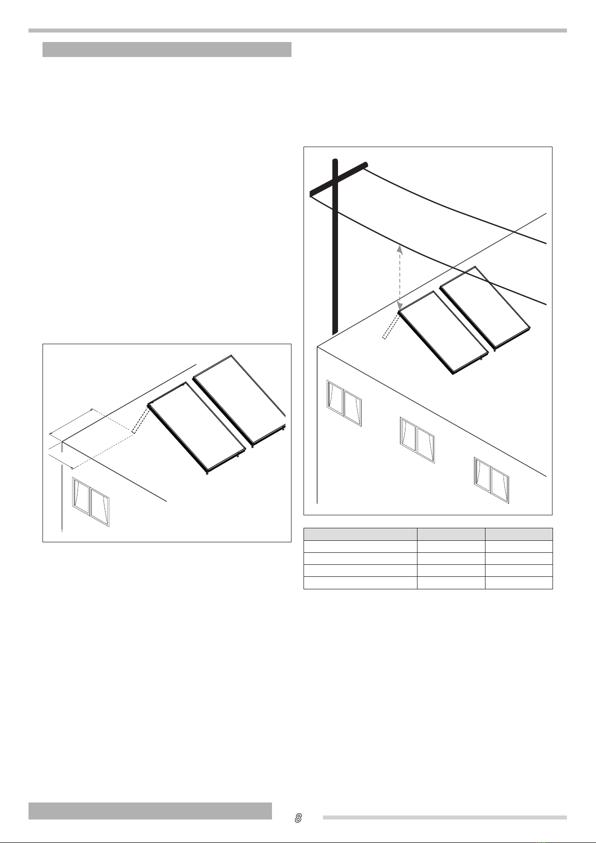
Solar collector pipes must be connected through a (yel-
low-green) connector of at least 16 mm2Cu (H07 V-U o
R) to the potential compensation main bar. If a lighting
rod is already installed, collectors can be integrated in
the existing system. If this is not the case, it is possible
to carry out earthing with a buried earth cable. The earth
duct must be laid outside the house. Furthermore, the
earth cable must be connected to the compensation bar
through a duct having the same diameter.
b
All pipes in the water circuit must be insulated in con-
formity to relevant standards. Lagging and insulation
must be protected against damage by the weather and
birds and animals.
b
The collector is suitable for a minimum inclination of 15°,
up to a maximum of 75°.
b
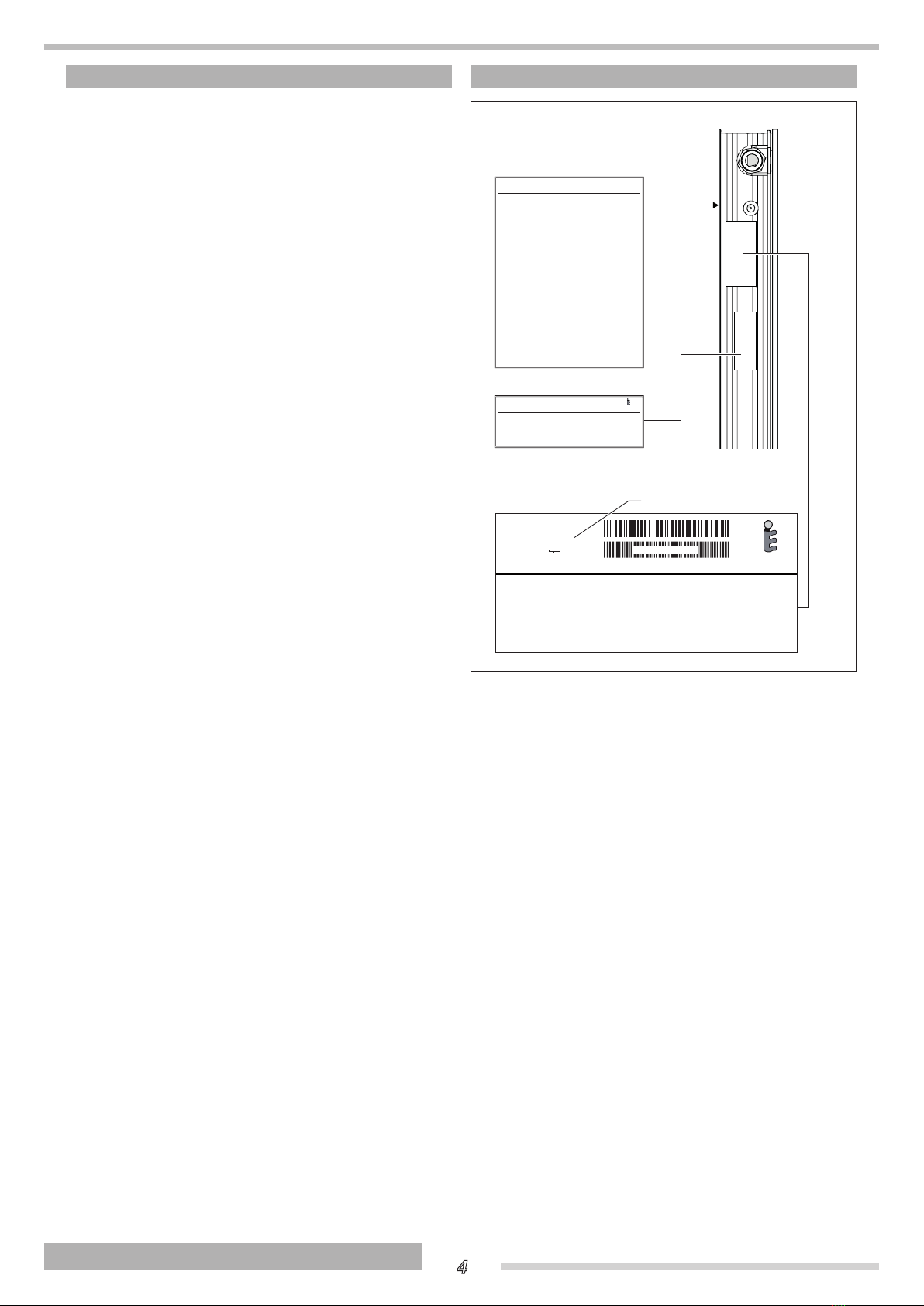
This instruction manual is an integral part of the prod-
uct. It must be kept safe and must ALWAYS accompany
the product, even if it is sold to another owner or trans-
ferred to another user or to another installation. If you
lose this manual, order a replacement immediately. Keep
the product purchase documents to be presented to the
Tauthorised Technical Assistance Centre to
request a service call under warranty.
b
Size the solar expansion tank so as to ensure complete
absorption of the expansion of the fluid contained within
the system, with reference to the prevailing regulations
on the matter. In particular, consider fluid characteris-
tics, considerable fluctuation of service temperature and
vapour that might be generated during solar collector
stagnation stage. Proper size of expansion tank ensures
setting off of all volume changes of the heat transfer fluid,
avoiding excessive pressure increase. Limited pressure
changes avoid reaching safety valve opening pressure
and the consequent fluid drainage.
PRECAUTIONS
b
Always wear safety goggles when drilling. Always wear
safety shoes, cut-proof protective gloves and a safety
helmet when performing installation work.
b
Before beginning installation work on roofs, install the
necessary fall prevention and fall arrest devices and en-
sure that all applicable safety standards are applied. Use
only tools and materials that conform to the safety stand-
ards that are applicable in the place of work.
b
Use only overalls with harness (with lacing or restraining
belt, connection ropes or bands, fall dampeners, heat
sinks) certified for the risk detected according to the type
of covering and allowing operating in complete safety.
b
The use of ladders leaned against walls can lead to se-
rious falls if the ladder slips, slides of falls. When using
ladders, always ensure that they are stable, and that suit-
able ladder stops are present. If possible secure the lad-
der with hooks. Make sure that there are no live electrical
wires near the ladder.
a
Never attempt to install the system without using suitable
personal protection equipment and without following all
applicable occupational safety standards.
a
Do not touch the product when barefoot or wet if it has
any electrical accessories installed in it.
a
Never clean or service the storage cylinder without first
turning the mains power switch OFF to disconnect all
electrical accessories (if fitted) from the mains electricity
supply.
a
If solar plant pressure decreases, it is forbidden to top
up with only water as there is a danger of freezing and
overheating.
a
Do not dispose of packaging material into the environ-
ment, or leave it within the reach of children, since it can
become a potential hazard. Dispose of packaging mate-
rial in compliance with applicable legislation.

4
ENGLISH GENERAL INFORMATION
GENERAL INFORMATION
DESCRIPTION OF THE APPLIANCE
The solar collector is a device able to intercept solar radiation
and convert it into thermal energy used to heat up a heat trans-
fer fluid, composed of a mix of water and glycol.
Solar collectors can be used in systems for domestic hot water
production or as a supplement to the heating system.
The main technical elements in the design of the solar collector
are:
- the intercepting plate (called absorber) that allows a
high energy absorption and limits its emission.
- the rock wool insulation
- the easy and flexible installation
- the integrability of the element with various covering
technologies
- the long lifespan.
IDENTIFICATION
Year of production
Data label
To be applied to the back of
the solar collector on installation
Serial number plate
Data plate
20127468CODICE :
TIPO : CP25TSS
S/N :
FABBRICATO IN ITALIA
da Riello S.p.A.
13000000 BAR CODE 128B
Anno di produzione
SERIALE PROGRESSIVO
EN 12975-1, ISO 9806
Certif.
Serial N°
Model
Codice . . . . . . . .
Modello . . . . . . .
Matricola . . . . . .
Codice . . . . . . . . . . . . . . . . . . . . .
Tipo . . . . . . . . . . . . . . . . . . . . . . .
Dimensioni. . . . . . . . . . . . . . . . . .
Superficie lorda . . . . . . . . . . . . . .
Superficie di apertura . . . . . . . . .
Superficie assorbitore . . . . . . . . .
Peso a vuoto . . . . . . . . . . . . . . . .
Massima pressione di esercizio .
Contenuto liquido . . . . . . . . . . . .
Massima concentrazione glicole .
Liquido termovettore . . . . . . . . . .
COLLETTORE SOLARE (neutro)
FABBRICATO IN ITALIA da Riello S.p.A.
Code
Temperatura di stagnazione . . . . °C
TCOLL_NEUTRO2
EN 12975-1, ISO 9806
Certif.
COLLETTORE SOLARE PIANO
DIMENSIONI: 2004X1148X85 mm
SUPERFICIE LORDA: 2,301m
2
TEMPERATURA DI STAGNAZIONE: 200°C
SUPERFICIE DI APERTURA:2,152m
2
CONTENUTO LIQUIDO: 1,7 l
SUPERFICIE ASSORBITORE: 2,140m
2
PESO A VUOTO: 44,0 kg LIQUIDO TERMOVETTORE:
ACQUA+GLICOLE PROPILENICO
MAX CONCENTRAZIONE GLICOLE: 50%
MAX PRESSIONE ESERCIZIO: 10 bar
b
If these plates or any other means of clearly identifying
the product are defaced, removed or lost, proper instal-
lation and servicing may be rendered difficult.

5ENGLISH
GENERAL INFORMATION
GENERAL INFORMATION
SYSTEM LAYOUT
Ventilation holes
(*) Alternative collector
return
(**) Alternative collector
outlet
The outlet and the
return must be connected
to opposite sides.
Direction of flow of
heat transfer liquid
Connector Ø 22 mm
Sealing elements
of connections
Glass
3,2 mm
Connection
ring nut,1"
85
Collector
outlet
Collector
return
Collector
probe socket
(**)
(*)
1195
1148
2004
46,5
TECHNICAL SPECIFICATIONS
DESCRIPTION TSOL 25/4 FLEX
Total area 2,301 m2
Exposed area 2,152 m2
Effective absorption area 2,140 m2
Water connections 2x 1”M / 2x 1”F Ø
Empty weight 44,0 kg
Liquid content 1,7 l
Recommended flow rate for each line per m2of collec-
tor 30 l
(h x m2)
Minimum flow rate for each line per m2of collector 20 l
(h x m2)
Maximum flow rate for each line per m2of collector 200 l
(h x m2)
Glass thickness 3,2 mm
Thickness of glass wool insulation 40 mm
Absorption (α)95 %
Emissivity (ε)4 %
Maximum permitted pressure 10 bar
Stagnation temperature 200 °C
Maximum number of collectors in a line 10 Vertical / 6 Horizontal n°
Installation Vertical/Horizontal -
Glass class U1 -

6
ENGLISH GENERAL INFORMATION
GENERAL INFORMATION
Efciency curve
0,80
0,85
0,70
0,75
0,60
0,65
0,50
0,55
0,45
0,40 0 0,01 0,02 0,03 0,04 0,05 0,06 0,07 0,08
Tm[m
2
K/W]
*
Description TSOL 25/4
FLEX
Optical efficiency (ηο) (*) 0,802 -
Thermal dispersion factor (a1)
(*) 4,28 W/(m2K)
Thermal dispersion tempera-
ture dependence factor (a2) (*) 0,0064 W/(m2K2)
IAM (50°) (*) 0,95 -
Efficiency (ηcol) (**) 62,0 %
(*)
Value referred to the opening area. Test according to ISO
9806 referred to mix of water and 33.3% glycol, flow rate
160 l/h and direct exposure G = 800W/m2.
Tm = (Coll._inlet _temp.+Coll._outlet_temp.)/2
T*m =
(Tm-T_ambient)/G
(**)
Calculated with a temperature difference of 40K between
the solar collector and the surrounding air, and with total
solar radiation of 1000 W/m2referred to the exposed area.
Pressure drop in solar collectors (*)
PRESSURE DROP (mbar)
10
0
20
30
40
50
0
100 200 300 400 500 600 700 800 900 1000
15
10
5
0
0 50 100 150 200 250 300 350 400
FLOW RATE (l/h)
(*) With antifreeze-water mix of 33,3% / 66,7% and heat transfer medium temperature = 20°C.
WIND AND SNOW LOADS ON COLLECTORS
The maximum allowable load for wind and snow (possibly combined) on the collector surface is 1500 Pa (corresponding to the
wind speed of 175 km/h).
To determine the maximum wind speed consider:
- building height
- solar system site
- exposure and topography (area/buildings)
The maximum snow load depends on the region and the altitude of the area.
b
Prevent the accumulation of snow on collectors by installing a snow-guard grille over collectors, or remove snow on a
regular basis

7ENGLISH
INSTALLATION
INSTALLATION
UNPACKING THE PRODUCT
Solar collectors are supplied in packages containing 1, 2 or 5
panels
Pallet contents:
- collector
- document envelopes containing instruction manual,
bar code labels and data label.
2
2
1
b
Be careful not to lose the two flat gaskets (1) in the corner
(2) of each collector.
b
The instruction manual is an integral part of the solar con-
nector. Once located, read it thoroughly and keep it safe.
b
STORE IN A DRY PLACE AND DO NOT EXPOSE TO DIRECT
SUNLIGHT UNTIL THE TIME OF INSTALLATION!
The pack-
aging is not designed to protect the product against rain
or humidity. It can also degrade if exposed to direct sun-
light. Failure to comply with these precautions could lead
to irreparable damage to the product.
b
A protective lm is applied on the collector glass, gener-
al and handling information is written on it. It must be re-
moved after the installation of the solar collector, only when
the operation of the system is required.
Installation
HANDLING
- Separate the solar collector from the wooden pallet by
removing the film wrapping
- Apply the data label (provided in the document enve-
lope) to the back of the solar collector
Once you have removed the outer packaging, proceed as fol-
lows to unpack and handle the solar collector:
- Tilt the solar collector slightly and grip it at the four
points shown (A) to lift it.
- Use a hoist or other suitable lifting equipment to hoist
the solar collector on to the roof.
Data label
A
A
A
A
Codice . . . . . . . .
Modello . . . . . . .
Matricola . . . . . .
Codice . . . . . . . . . . . . . . . . . . . . .
Tipo . . . . . . . . . . . . . . . . . . . . . . .
Dimensioni. . . . . . . . . . . . . . . . . .
Superficie lorda . . . . . . . . . . . . . .
Superficie di apertura . . . . . . . . .
Superficie assorbitore . . . . . . . . .
Peso a vuoto . . . . . . . . . . . . . . . .
Massima pressione di esercizio .
Contenuto liquido . . . . . . . . . . . .
Massima concentrazione glicole .
Liquido termovettore . . . . . . . . . .
COLLETTORE SOLARE (neutro)
FABBRICATO IN ITALIA da Riello S.p.A.
Temperatura di stagnazione . . . . °C
TCOLL_NEUTRO2
b
Wear suitable personal protective equipment and use
suitable safety devices.
a
Do not dispose of packaging material into the environ-
ment, or leave it within the reach of children, since it can
become a potential hazard. Dispose of packaging mate-
rial in compliance with applicable legislation.
a
Do not lift the solar collector by its water fittings.

8
ENGLISH INSTALLATION
INSTALLATION
INSTALLATION AREA
Select the best possible orientation for the solar collectors (ide-
ally facing south). Avoid positions that are shaded by plants,
trees, buildings or hills, etc. during the day.
In systems in which the summer load is predominant (produc-
tion of domestic hot water) aim the collector from east to west
with a variable inclination from 20° to 60°. The ideal direction is
southwards, with inclination equal to the latitude of the location
-10°. If the system sustains the greatest thermal load in the
winter (as in systems that combine domestic hot water pro-
duction with central heating), install the collectors facing south
(or south-east or south-west) at an angle greater than 35°. The
ideal orientation is southwards, at an angle equal to the latitude
of the location plus 10°.
Remove all gravel and detritus from the surface on which the
system is to be installed.
Do not use flat roof or sloping roof mounting frames to install
any other equipment. They are designed only for use with
Tsolar water heating systems.
The installation of the solar field changes the pre-existing
structure of the roof. It is necessary to check and possibly
adapt all the roof elements to prevent any seepages or dam-
ages caused by wind and/or snow.
>1,5 m
>1,5 m
b
Collectors must be installed at a safety distance from
active parts of electric lines and electric systems as re-
quired by the laws and regulations in force in the country
of installation.
In the absence of specific rules, the minimum installation dis-
tance required minus the side movements of conductors due
to the action of the wind and of the lowering in height due to
thermal conditions is as follows:
H
Voltage range H
< 1 kV 3 m
1 ÷ 30 kV 3,5 m
30 ÷ 132 kV 5 m
< 132 kV 7 m
b
Contact with open, live electrical wires may lead to elec-
trocution and may even be fatal.
b
Non-electrical works near live unprotected electric ducts
with which a contact is possible must be carried out in
accordance with laws and regulations in force in the
country of installation.

9ENGLISH
INSTALLATION
INSTALLATION
INSTALLATION ON FLAT ROOFS WITH BALLAST
For checks of allowable loads contact a specialised technician.
In case of installations on flat roofs that cannot be drilled use ballasts (not supplied) fairly distributed on all the bearing points,
as shown in the figure.
kg
Wind speed, km/h Inclination angle of solar col-
lectors
Mass in kg, distributed on the various bearing
points, to secure a collector from wind lifting
100 30°-45° 135
130 30°-45° 255
150 30°-45° 355
The indicated values are valid both for vertical and horizontal installation.

10
ENGLISH INSTALLATION
INSTALLATION
WATER CONNECTIONS
b
During installation, pay attention to the position of the probe with respect to the collector. The collector probe must always
be in the upper section of the panel as indicated in the figures below.
Union
sensor
pocket
seal ring
toward the
heat transfer
circuit
seal ring
from the
heat transfer
circuit
When tightening a fitting,
HOLD THE OPPOSITE
FITTING STEADY WITH
A SECOND TOOL
to avoid damage
seal ring
Plug
captive nut
captive nut
seal ring
seal ring
Plug
captive nut
seal ring
Union
captive nut
When tightening a fitting,
HOLD THE OPPOSITE
FITTING STEADY WITH
A SECOND TOOL
to avoid damage
sensor
pocket
toward the
heat transfer
circuit
from the
heat transfer
circuit
captive nut
Ring
nut
seal ring
captive nut
Ring
nut
seal ring
captive nut
Ring nut
seal ring
insulated connector
pipe
seal ring
Plug
HORIZONTAL CONFIGURATION
VERTICAL CONFIGURATION

11 ENGLISH
INSTALLATION
INSTALLATION
Vertical conguration
Collectors are connected with each other so that the heat
transfer fluid crosses them in parallel. Connection with the heat
exchange circuit towards the exchanger must be made on the
side of probe socket (T) of the last collector of the series (see
figure). The positioning of the socket on the collector allows the
maximum transfer of heat accumulated in the panels.
It is also possible to connect more than one line of solar collec-
tors, both in series (provided that the number of solar collec-
tors does not exceed 10 units per each series) and in parallel.
In any case the circuit must be hydraulically balanced (see the
following example diagrams).
Horizontal conguration
Collectors in the same line must be connected so that the heat
transfer fluid flows through them in series. Connection with the
heat exchange circuit towards the exchanger must be made
on the side of probe socket (T) of the last collector of the series
(see figure).
Lines of solar collectors can be connected either in series
(provided each line contains no more than 6 collectors) or in
parallel. The complete circuit must always be hydraulically bal-
anced. See the following sample layouts.
Connection between collectors must be carried out only using
the junction connector (including the proper insulation) sup-
plied separately. This connector is used as expansion joint be-
tween collectors.
Two lines in series
Vertical conguration
Two lines in parallel
Vertical conguration
T T
Horizontal conguration Horizontal conguration
T
T
T
Diameter of connection pipes for a specic ow rate of 30 lt/m2h
Total surface area (m2) 2 - 4 6 - 12 14 - 20
Diameter of copper pipe (mm) 10 - 12 14 18
Diameter of steel pipe (inch) 3/8" - 1/2" 1/2" 3/4"
b
Do not fix the ends of lines of solar collectors rigidly: leave them free to absorb thermal expansion. If this is not possible, fit
an expansion joint at each end.

12
ENGLISH INSTALLATION
INSTALLATION
SOURCE WATER SYSTEM
1
Solar collector
2
Storage cylinder
3
Collector probe
4
Disconnect valves
5
Non-return valve
6
Temperature gauge
7
Vent valve
8
Safety valve
9
Pressure gauge
10
Drain
11
Expansion vessel
12
Pump
13
Flow regulator
14
Flow meter
15
Vent cock
16
Manual bleed valve (accessory)
17
Heat transfer fluid recovery
M
Collector outlet
R
Collector return
3
11
R
M
°C
M
4
4
4
9
8
11
17
10
13
14
2
6
12
Valve group
5
7
15
16
T
b
If copper pipes are used, joints must be hot brazed.
b
We recommend the use of stainless steel pipes specially made for solar collectors for the outlet, return and probe pipes.
The probe cable should be of the shielded type.
b
Do not use plastic or multistrate pipes. Operating temperature can exceed 180°C.
b
Pipe lagging must be able to resist high temperatures (180°C).

13 ENGLISH
INSTALLATION
INSTALLATION
FILLING AND EMPTYING
Before system commissioning it is necessary to wash and fill it.
Solar collectors are exposed to the risk of frost during winter,
as they are installed outdoor. Moreover, they can reach high
temperatures in stagnation conditions, consider these things
when choosing the heat transfer fluid.
b
If copper piping has been used and joints have been hot
brazed, flush out the system to remove any brazing res-
idues. Seal test the system after you have flushed it out.
Fill the solar collector with glycol/water mix immediately
after flushing it out, because flushing water may remain
trapped in the circuit (with a consequent risk of freezing).
b
For system washing, filling and emptying, follow the in-
structions contained in the manual of the matched solar
station.
b
Filling, emptying and venting must be carried out with
collectors at ambient temperature and protected from
solar radiation.
A
7
°C
Manual
bleed valve
(accessory)
Anti-freez mix
Heat exchanger
of solar
Solar collector
Heat
transfer fluid
filling pump
Water control system
R
M
M
T
DEVICE CLEANING AND MAINTENANCE
b
The following operations must be exclusively performed
by Technical Assistance Centre
It is recommended to clean the glass once a year, as the de-
posit of dust and leaves reduces system efficiency.
The collector must be cleaned with water or water and soap.
Dry the collector at the end of cleaning operations.
a
Do not use abrasive products, petrol or triethylene.
The heat transfer fluid must be checked every 2 years to ver-
ify the effectiveness of water and glycol mix, including its pH
value.
- Check the antifreeze with the suitable instrument - re-
fractometer or hydrometer- (nominal value approx.
-30°C): if the limit value of -26°C is exceeded, replace
or top-up the antifreeze.
- Use litmus paper to check the pH (nominal value ap-
prox. 7.5). If the measured value is below 7, change the
heat transfer liquid.
Check the integrity of insulation and expansion joints.
RECYCLING AND DISPOSAL
The device is primarily composed of:
At the end of the device's useful life, these components must
be separated and disposed of according to current regulations
in the country of installation.
Material Component
Glass Cover
Brass - Copper - Aluminium Absorber
Rock wool Insulation
Aluminium - Steel External frame
Silicone - PA66 Sealing elements of connec-
tions

14
ENGLISH END USER
END USER
END USER INSTRUCTIONS
Refer to the GENERAL SAFETY INFORMATION and PRE-
CAUTIONS section for safety-related information.
EXTERNAL MAINTENANCE
It is recommended:
- To clean the glass once a year, as the deposit of dust
and leaves reduces system efficiency
- To check the heat transfer fluid to verify its effectiveness
every two years
- To check the integrity of solar collector insulations and
any expansion joints, every two years.
For cleaning operations and solar collector efciency
check, contact the nearest Technical Assistance Centre.
Enduser

15 ENGLISH
END USER
END USER

20134610 - Rev. 1 (10/17)
RIELLO S.p.A.
Via Ing. Pilade Riello, 7
37045 - Legnago (VR)
www.thermital.it
The manufacturer strives to continuously improve all products. Appearance, dimensions, technical
specications, standard equipment and accessories are therefore liable to modication without
notice.
Table of contents