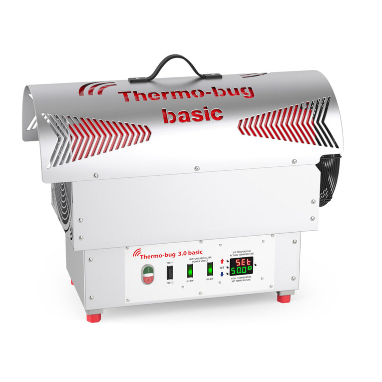
Thermo-bug 2.0 basic User manual

Operating Manual
Thermo-bug® 2.0

2 | Thermo-bug 2.0 basic Operating manual 0218
Preface
Thermo-bug® 2.0 basic
Before taking this high-temperature
radiator into operation, please read
this operation manual with care and
familiarise yourself with the operating
elements.
In particular the danger notes should be
given increased attention.
We assume no liability for damage from
improper handling and application; the
warranty claim lapses.
The practical
thermal exterminator for
analogue single
operation
Thermo-bug® 2.0 basic
Thermo-bug® 2.0
basic
Operating Manual
Before delivery, the radiator has been
reviewed and tested for function.
Please check the devicefor possible
transport damage after delivery.

Thermo-bug 2.0 basic | 3
Operating manual 0218
Contents
04 First steps
06 Display and target value settings
08 Product properties and
misdiagnosis
10 Safety notes, guarantees and
general notes

Thermo-bug® 2.0
basic
First steps
Main switch
Power switch 4.5 KW
Power switch 9 KW
3
3
Sockets for temperature sensor
Display for temperature sensor
4 | Thermo-bug 2.0 basic Operating manual 0218

Commissioning
After connection of the Thermo-bug®
2.0 basic to the mains 3x400 V, fuse 16 A:
1. Switch on the main switch (2). The fan
is running.
2. Insert the temperature sensor in
socket (2 .
3. Power switch (2) : The heating is
running at half power 4.5 KW.
Power switch (3) : The heating is
running at full power 9 KW.
The switches must be pushed in
sequence in the order – to get
full power.
Sockets for temperature sensor
Display for temperature sensor
The display (2) can be used to set the
desired temperature and to read the
current temperature. The maximum
temperature can be set via the display
2) as well (see below).
The temperature sensor should be
placed at a height of approx. 1 m in
open space (not covered), since the
pre-set ambient air temperature will
not be achieved otherwise.
To deactivate the Thermo-bug® 2.0
basic, observe the instructions on
page 7.
Thermo-bug 2.0 basic | 5
3
3
Operating manual 0218

6 | Thermo-bug 2.0 basic
Thermo-bug® 2.0
basic
Display and
target value settings
0.0.0.
SET
OUT
ALM
H/C
Indicator lamps
SET ●= Set value setting active
OUT ●= Output relay active
ALM ●= Alarm relay active
H/C ●= Cooling function active
H/C ●= Heating function active
Quit button (exit menu)
Function button for target value
setting and parameterisation
Arrows and parameterisation
Operating manual 0218

Target value settings
The target value setting serves to adjust
the desired value.
1. Hold the function button down
for 3 seconds.
2. Use the arrows to set the
desired value now.
3. Use the function button bestätigen
to conrm the setting.
Thermo-bug 2.0 basic | 7
Deactivation
Important: Switch o power
switch and of the
Thermo-bug® 2.0 basic and let the
fan lag for at least 5 minutes
(without heating) so that the device
can cool o!
Do not simply pull the plug!
This would lead to a danger that
the connection cables overheat!
Then switch o via the main
switch and disconnect from the
mains.
3
= 3 Sek. – – –&
0.0.0
&
Quit button (exit menu)
Function button for target value
setting and parameterisation
Arrows and parameterisation
Operating manual 0218

8 | Thermo-bug 2.0 basic
Thermo-bug® 2.0
basic
Product properties
and troubleshooting
nPower switch for 4.5 KW
(half power)
nPower switch for 9 KW
(full power)
nPluggable external temperature sensor
with 4 m cable
nTemperature display with adjustable
temperature
n230 V socket for the Thermo-bug®
airblower with a 4A fuse
nHigh-performance fan for high
temperatures
nOverheating protection with
automatic resetting
nHousing protection type IP54
nEasy handling from low dead weight
(15 kg)
Operating manual 0218

Thermo-bug 2.0 basic | 9
Error diagnosis (only when the device is powered down (pull the plug))
Error
1) Radiator without
function in spite of
mains connection
2) Heating elements glow
3) Fan is running, but
heating is not or only at
half power
4) Fan noise
5) Thermo-bug 2.0 basic
does not work
Cause
Plug loose or no contact,
no supply voltage
Fuse blown
Device overheated
Main switch o, input
voltage too high
Air supply blocked, fan
standing
Temperature controller is
not on or defective
PCB fuse defective
Imbalance, bearing
damage
No temperature sensor
inserted
Remedy
Attach plug, insert
again
New fuse
Let cool o by 15 °C,
switch on
Measure mains voltage
Keep air supply free,
cool o
Activate, replace
Replace fuse on the
PCB
Inform manufacturer
Insert temperature
sensor
Troubleshooting
nIf the errors continue to occur after remediation, contact the manufacturer
without delay.
Operating manual 0218

10 | Thermo-bug 2.0 basic
Safety measures
nNever work on the device while it
is live!
nNote the power data of the rating
plate when connecting!
nThe connection line must be
secured via the power switch and
circuit breaker!
nConnection lines must have a
corresponding line cross-section!
nMaintenance work must only be
performed by qualied specialists!
Maintenance and spare parts
nAt longer standstill times, remove
any dust deposits on the heating
rods with compressed air.
nOnly use genuine spare parts.
nA damaged mains cable must only
be replaced by a specialist.
Guarantee
The guarantee period shall be 12
months after the date of purchase of
the device.
Any repairs will be performed free of
charge during this warranty period if
the defective parts show faults during
our inspection.
Repair will not extend the warranty
period.
The following damage shall be
excluded from warranty:
nUnintended us
nNon-observation of the instructions
nImproper use
nRegular wear
nChanges to the device
nImproper repairs or maintenance
work
We are not liable for costs or damage
caused by use of the device.
Danger notes
nKeep small parts away from the proximity of running fans.
nNever cover the radiator in operation!
nDo not store any ammable materials near the radiator!
Operating manual 0218

EC declaration of conformity
according to the EC machinery
directive 2006/42/EC from 17 May
2006, Annex II A
We declare that the following
machine is designed and built in the
version marketed by us to comply
with the basic safety and health
requirements of the EC directive
2006/42/EC.
Any changes to the machine not
coordinated with us will render this
declaration void.
Description of the machine
Function: High temperature radiator
Type/Model: EL-K-9KW
Correspondence with other
directives/provisions also
applicable to the product is
declared: EMC directive (2004/
108/EC) from 15 December 2004
Applied harmonised
standards, specically:
nDIN EN 12100-1 Safety of
machinery – Basic terms, general
principles of design, part 1: General
terminology, method
nDIN EN 12100-2 Safety of
machinery – Basic terms, general
principles of design, part 2: Technical
leading principles and specications:
nDIN EN 60204-1 Safety of
machinery – Electrical equipment
of machinery, part 1: General
requirements
nDIN EN ISO13849 Safety of
machinery - Safetyrelated parts of
controls
Other applied technical standards
and specications:
nDIN 40719 Marking of elect.
operating equipment
nVDE 0110/750 Dimensioning of
creepage and air distances of elect.
operating equipment
nVDE 0298 Current resilience of lines
nVDE0 0470 Part 1 Protection types
through housing
nVDE 0701 Inspection of elect. devices
Storage of the documents according to
annex VI.
Thermo-bug 2.0 basic | 11
Operating manual 0218

Thermo-bug® GmbH
Felix-Wankel-Straße 17
88339 Bad Waldsee
Phone +49 (0 )7524/401 17-27
Fax +49 (0)7524/401 17-28
www.thermo-bug.com
Krempel & Co. Werbeagentur GmbH | Fotos: Fotostudio Jacobs / Krempel & Co.
Thermo-bug®ist eine eingetragene Marke der Thermo-bug®GmbH
Thermo-bug® 2.0
basic
Operating Manual
Other Thermo-bug Heater manuals
Popular Heater manuals by other brands
Sawo
Sawo CIRRUS ROCK CRR-40NB manual
Convair
Convair CPH01B owner's manual

Salda
Salda VEKA 350 EC Mounting and installation instructions

Hygiene
Hygiene HATHOR 793 Use and maintenance
HeatStar
HeatStar HS115TC Operating instructions and owner's manual

Elnur Gabarron
Elnur Gabarron CP-TURBO Installation instructions and user guide
Kampmann
Kampmann PowerKon LT Assembly instructions

Ontel
Ontel HANDY HEATER HEATWAVE instruction manual
Uni-pak
Uni-pak GH Series Installation, operation & maintenance manual
AUTOTERM
AUTOTERM PLANAR-8DM-12 Operation manual

Eldom Invest
Eldom Invest RH10N MANUAL FOR INSTALLATION, OPERATION AND MAINTENANCE

KORADO
KORADO KORALUX-E Series manual
