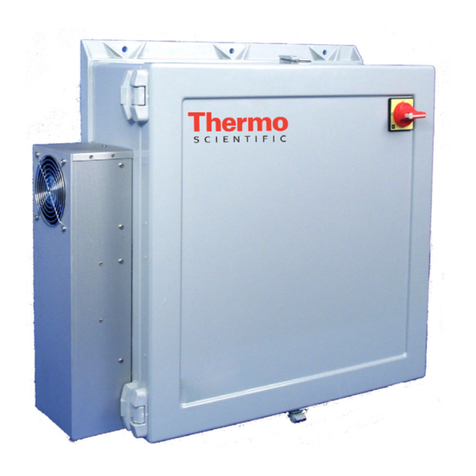
Thermo Scientific 3060 Operating instructions

Model
3060
Portable IR CO2Controller
Operating and Maintenance Manual
Manual No: 7003060 Rev. 1

Model 3060 _____________________________________________________________________________
i
Read This Instru tion Manual.
Failure to read, understand and follow the instructions in
this manual may result in damage to the unit, injury to
operating personnel, and poor equipment performance.
CAUTION! All internal adjustments and maintenance must
e performed y qualified service personnel.
The material in this manual is for information purposes only. The
contents and the product it describes are subject to change
without notice. Thermo Fisher Scientific makes no representa-
tions or warranties with respect to this manual. n no event shall
Thermo be held liable for any damages, direct or incidental,
arising out of or related to the use of this manual.
MANUAL NUMBER 7003060
1 -- 12/04/2018 Changed R sensor TF
REV ECR/ECN DA E DESCRIP ION By

Model 3060 _____________________________________________________________________________
ii
Important operating and/or maintenance instructions. Read the accompanying text carefully.
Ce sym ole attire l'attention de l'utilisateur sur des instructions importantes de fonctionnement et/ou d'entretien. Il
peut être utilisé seul ou avec d'autres sym oles de sécurité. Lire attentivement le texte d'accompagnement.
Wichtige Betrie s- und/oder Wartungshinweise. Lesen Sie den nachfolgenden Text sorgfältig.
Importante instruccions de operacion y/o mantenimiento. Lea el texto acompanante cuidadosamente.
Potential electrical hazards. Only qualified persons should perform procedures associated with this sym ol.
Ce sym ole attire l'attention de l'utilisateur sur des risques électriques potentiels. Seules des personnes qualifiées
doivent appliquer les instructions et les procédures associées à ce sym ole.
Gefahr von Stromschlägen. Nur qualifizierte Personen sollten die Tätigkeiten ausführen, die mit diesem Sym ol eze-
ichnet sind.
Potencial de riesgos electricos. Solo personas das capacitadadas de en ejecutar los procedimientos asociadas con este
sim ulo.
Equipment eing maintained or serviced must e turned off and locked off to prevent possi le injury.
Risques potentiels liés à l'énergie. L'équipement en entretien ou en maintenance doit être éteint et mis sous clé pour
éviter des lessures possi les.
Geräte, an denen Wartungs- oder Servicear eiten durchgeführt werden, müssen a geschaltet und a geschlossen wer-
den, um Verletzungen zu vermeiden.
El equipo reci iendo servicio o mantenimiento de e ser apagado y segurado para prevenir danos.
Hot surface(s) present which may cause urns to unprotected skin, or to materials which may e damaged y elevated
temperatures.
Présence de surface(s) chaude(s) pouvant causer des rûlures sur la peau non protégée, ou sur des matières pouvant
être endommagées par des températures élevées.
Heiße O erfläche(n) können ungeschützter Haut Ver rennungen zufügen oder Schäden an Materialien verursachen,
die nicht hitze eständig sind.
Superficias calientes que pueden causar quemaduras a piel sin proteccion o a materiales que pueden estar danados
por elevadas temperaturas.
Ö Always use the proper protective equipment (clothing, gloves, goggles, etc.)
Ö Always dissipate extreme cold or heat and wear protective clothing.
Ö Always follow good hygiene practices.
Ö Each individual is responsible for his or her own safety.

Model 3060 _____________________________________________________________________________
iii
Do You Need Information or Assistance on
Thermo Scientific Products?
If you do, please contact us 8:00 a.m. to 6:00 p.m. (Eastern Time) at:
1-740-373-4763 Direct
1-800-438-4851 Toll Free, U.S. and Canada
1-877-213-8051 FAX
http://www.thermofisher.com Internet Worldwide Web Home Page
service.led.marietta@thermofisher.com Tech Support Email Address
Certified Service Web Pagewww.unitylabservices.com
Our staff can provide information on pricing and give you quotations. We canSales Support
take your order and provide delivery information on major equipment items or make
arrangements to have your local sales representative contact you. Our products are listed on the
Internet and we can be contacted through our Internet home page.
Our staff can supply technical information about proper setup, operation orService Support
troubleshooting of your equipment. We can fill your needs for spare or replacement parts or
provide you with on-site service. We can also provide you with a quotation on our Extended
Warranty for your Thermo Scientific products.
Whatever Thermo Scientific products you need or use, we will be happy to discuss your
applications. If you are experiencing technical problems, working together, we will help you
locate the problem and, chances are, correct it yourself...over the telephone without a service
call.
When more extensive service is necessary, we will assist you with direct factory trained
technicians or a qualified service organization for on-the-spot repair. If your service need is
covered by the warranty, we will arrange for the unit to be repaired at our expense and to your
satisfaction.
Regardless of your needs, our professional telephone technicians are available to assist you
Monday through Friday from 8:00 a.m. to 6:00 p.m. Eastern Time. Please contact us by
telephone or fax. If you wish to write, our mailing address is:
Thermo Fisher Scientific (Asheville) LLC
401 Millcreek Road, Box 649
Marietta, OH 45750
International customers, please contact your local Thermo Scientific distributor.

Model 3060 _____________________________________________________________________________
iv
able of Contents
Se tion 1 - Re eiving
1.1 Preliminary nspection . . . . . . . . . . . . . . . . . . . . . . . . .1-1
1.2 Visible Loss or Damage . . . . . . . . . . . . . . . . . . . . . . . .1-1
1.3 Responsibility for Shipping Damage . . . . . . . . . . . . . .1-1
Se tion 2 - Installation and Start-Up
2.1 ntroduction . . . . . . . . . . . . . . . . . . . . . . . . . . . . . . . . . .2-1
2.2 nstalling the CO2Control and Sensor . . . . . . . . . . . .2-1
2.3 CO2Outlet . . . . . . . . . . . . . . . . . . . . . . . . . . . . . . . . . .2-1
2.4 CO2Sample Tube . . . . . . . . . . . . . . . . . . . . . . . . . . . . .2-2
2.5 Connecting the CO2Source . . . . . . . . . . . . . . . . . . . . .2-2
2.6 Power Connection . . . . . . . . . . . . . . . . . . . . . . . . . . . . .2-2
2.7 Sealing the ncubator Cabinet . . . . . . . . . . . . . . . . . . . .2-2
2.8 Remote Alarm Contacts and 4-20 mA . . . . . . . . . . . . .2-2
Se tion 3 - Control Panel Operation
3.1 CO2Controller and ndicator . . . . . . . . . . . . . . . . . . . .3-1
3.2 Setting the CO2Content . . . . . . . . . . . . . . . . . . . . . . . .3-1
3.3 CO2Alarm . . . . . . . . . . . . . . . . . . . . . . . . . . . . . . . . . .3-1
3.4 CO2nject . . . . . . . . . . . . . . . . . . . . . . . . . . . . . . . . . . .3-1
3.5 Sample Port . . . . . . . . . . . . . . . . . . . . . . . . . . . . . . . . . .3-1
Se tion 4 - Servi e
4.1 Program CO2 Controller . . . . . . . . . . . . . . . . . . . . . . . .4-1
4.2 Remote Software Lockout . . . . . . . . . . . . . . . . . . . . . .4-1
4.3 Restore Software Lockout . . . . . . . . . . . . . . . . . . . . . . .4-1
4.4 Controller Configuration . . . . . . . . . . . . . . . . . . . . . . . .4-1
4.5 Offset Calibration . . . . . . . . . . . . . . . . . . . . . . . . . . . . .4-1
4.6 Electrical Servicing . . . . . . . . . . . . . . . . . . . . . . . . . . . .4-1
Se tion 5 - Spe ifi ations
Se tion 6 - Parts List
Se tion 7 - S hemati s
Se tion 8 - Warranty Information

Model 3060 ___________________________________________________________________________________Receiving
1 - 1
Section 1 - Receiving
1.1 Preliminary Inspection
This item was thoroughly inspected and carefully packed
prior to shipment and all necessary precautions were taken to
ensure safe arrival of the merchandise at its destination.
mmediately upon receipt, before the unit is moved from the
receiving area, carefully examine the shipment for loss or
damage. Unpack the shipment and inspect both interior and
exterior for any in-transit damage.
1.2 Visible Loss or Damage
f any loss or damage is discovered, note any discrepancies
on the delivery receipt. Failure to adequately describe such
evidence of loss or damage may result in the carrier refusing to
honor a damage claim. mmediately call the delivering carrier
and request that their representative perform an inspection. Do
not discard any of the packing material and under no
circumstances move the shipment from the receiving area.
1.3 Responsibility for Shipping Damage
For products shipped F.O.B. Marietta, Ohio, the
responsibility of Thermo Fisher Scientific ends when
themerchandise is loaded onto the carrier's vehicle.
On F.O.B. Destination shipments, Thermo and the carrier's
responsibility ends when your Receiving Department personnel
sign a free and clear delivery receipt.
Whenever possible, Thermo will assist in settling claims
for loss or in-transit damage.

Section 2 - Installation and Start-Up
2.1 Introduction
The Model 3060 is a portable system designed to add
CO2control to any incubator with stable temperature and
humidity. This unit contains an R (infrared) sensor.
2.2 Installing the CO2Control and Sensor
nstall the CO2control near the incubator cabinet. Route
the power supply to the nearest outlet. Select the appropriate
plug and attach it to the power supply as shown in figure 2-2.
The power supply is rated for 100-240 VAC, 50/60 Hz.
Route the sensor into the cabinet through an available
access port and attach it to an interior wall using the bracket
proviided. The sensor should be located in the airflow near the
positive pressure of the blower motor. Any slack in the cable
should be taken up on the outside of the unit.
2.3 CO2Outlet (Refer to Figure 2-1)
The CO2outlet tubing should be connected to the port
labeled Out. Route the outlet tubing into the chamber and locate
close to the blower motor negative pressure side. This location
will help mix the air and CO2to promote uniformity. Avoid
severely bending the tubing.
Model 3060 ___________________________________________________________________________________ nstallation
2 - 1
Figure 2-1
Model 3060 Ba k View
Figure 2-2
Plug

2.4 CO2Sample ube (Refer to Figure 2-1)
The sample tubing connects to the sample port on the back
of the controller. Route the open end of the tubing into the
incubator chamber so that the end of the tube is positioned near
the center of the chamber. To determine the degree of CO2
distribution uniformity, samples may be taken from a number of
locations within the chamber.
Use the sample port located on the front of the control
panel to check the CO2percentage in the chamber by an
independent instrument such as a Fyrite..
Do not locate the end of the sample tu ing
near the CO2 sensor or the inject tu ing. If the
sample is taken while CO2 injection is
occurring, an a normally high reading will e
o tained.
2.5 Connecting the CO2Source (Refer to Figure 2-1)
For the most economical use, the liquid CO2supply tanks
should be without siphon tubes, so that only CO2gas enters the
incubator injection system. Two tanks may be joined together
with a manifold to ensure a continuous CO2supply.
nstall a two-stage pressure regulator, with indicating
gauges, at the supply cylinder outlet. The high-pressure gauge
should have an indicating range of 0 to 2000 psig to monitor
tank pressure. The low-pressure gauge should have an
indicating range of 0 to 30 psig to monitor input pressure to the
incubator injection system. A suitable two-stage pressure
regulator is available.
The CO2source must be regulated at a pressure level
between 5 and 10 psig. Higher pressure levels may damage the
CO2control system. The user should determine the most
economical pressure level, between 5 and 10 psig appropriate
for the desired CO2percentage in the chamber. Use only suffi-
cient pressure to maintain recovery time after door openings.
To connect the CO2supply:
1. Connect the CO2tubing to the 1/4” hose fitting on the
back of the 3060 labeled In.
2. Check the tubing connection for leaks.
2.6 Power Connection
The power supply is the mains disconnect. See the
electrical schematic for exact electrical specifications.
2.7 Sealing the Incubator Cabinet
All sample ports and access holes in the incubator cabinet
must be capped. f the chamber is not properly sealed, CO2 will
drain from the chamber and the temperature and humidity
control will be affected.
2.8 Remote Alarm Contacts and 4-20 mA
The controller is equipped with 4-20mA output for the
remote transmission of CO2data. A terminal strip is located on
the back of the controller for convenience. Refer to Figure 2-3
for terminal pin identification. The output is scaled for 0 - 20%
CO2.
Remote alarm connections are also included on the termi-
nal strip (Figure 2-3) providing Normally Open (N.O.) and
Normally Closed (N.C.) contacts. C is the Common terminal.
The remote alarm will activate when the CO2percentage moves
outside of the set alarm limits in the event of a power outage..
Model 3060 ___________________________________________________________________________________ nstallation
2 - 2
Figure 2-3 Remote Alarm Conta ts

3.4 CO2Inject
The amber CO2light will illuminate when CO2gas is
being injected into the incubator.
3.5 Sample Port
A sample port is located on the control panel for checking
CO2percentage in the incubator chamber by independent
means, as with a Fyrite, or similar CO2test instrument.
To prevent CO2loss, the sample port must e
capped when it is not in use.
Model 3060 __________________________________________________________________________ Control Panel Operation
3 - 1
Section 3 - Control Panel Operation
3.1 CO2Controller and Indicator
The controller provides for both setpoint adjustment and
readout of actual CO2percentage in the chamber. During
normal operation, the upper display on the Watlow PM
controller indicates the actual CO2percentage in the chamber.
The lower display indicates the CO2set point.
3.2 Setting the CO2Content
To set the CO2content (0% to 20%), press the Up or Down
Arrow keys on the Watlow PM Controller. The content is set in
1% increments and is shown in the lower display.
3.3 CO2Alarm
The CO2alarm is factory set to activate when the chamber
CO2content deviates from configured alarm set points (see
configuration record). When a CO2alarm occurs, the CO2
Alarm indicator on the control panel lights and the audible
alarm sounds.
The CO2alarm high and low setpoints are established
through the Watlow PM CO2controller (ALO, and AH ). Refer
to the Configuration Record included at the end of Section 4.
Figure 3-1 Model 3060 Control Panel

4.3 Restore Software Lockout
To turn the software lockout back on.
1. Set Lock Values back to previous setting.
4.4 Controller Configuration
Copies of the Watlow configuration record is included at the
end of this section.
CAUTION! Do not re-configure the controller without first
consulting the Techincal Services Department.
4.5 Offset Calibration
t may be necessary to calibrate the controller to match an
independent measurement. To do so, follow the next few steps.
1. Press the “Remote Software Lockout” procedure in this
section.
2. Verify actual CO2chamber content with an independent
instrument of known accuracy.
3. Allow approximately 30 minutes for the incubator to
stabilize.
4. Press Up and Down Arrow keys simultaneously for 3
seconds. The word “OPEr” appears in the lower display.
5. Press Down arrow until “Ai” appears in the upper display.
6. Press the Advance Key until “i.CA” appears in the lower
display. Press Up or Down arrow Key to either add or
subtract an offset value. The Value is the difference
between the actual value shown on the controller, and the
reference sensor value.
7. Press the nfinity Key until the display reverts to normal
operation.
8. Perform the “Restore Software Lockout” procedure in this
section.
4.6 Electrical Servicing
No internal electrical servicing should be required for the
unit under conditions of normal use. f electrical servicing
should become necessary, it should be performed by qualified
electrical service personnel.
Refer to the electrical schematics, and wiring diagrams
provided in this manual.
Model 3060 ___________________________________________________________________________________Service
4 - 1
Section 4 - Service
Servicing is to e performed y qualified service
personnel only.
4.1 Program CO2 Controller
The Watlow CO2 controller has been set at the factory to
operate the incubator within the specifications listed in the
Specifications section of this manual. Reference copies of the
Watlow configuration records are included at the end of this
section.
To prevent tampering, software lockouts are employed in
the system. These lockouts must only be removed by persons
skilled in configuring controller software.
CAUTION! Re-programming either the temperature or
humidity controllers alters the factory defaults and will
seriously alter the performance of the incu ator. This may
also void the warranty . Do not re-configure the controllers
without first consulting the Technical Services Department.
4.2 Remote Software Lockout
1. Press the Advance and nfinity Key at the same time and
hold them for about six seconds. The word “Fcty” (factory)
will appear in the bottom display. f numbers in the bottom
display begin to scroll up or down, the keys have not been
pressed simultaneously. Try again.
2. Press the Up Arrow until “LOC” (lock) appears in the upper
display. The word “Fcty” will remain in the lower display.
3. Press the Advance key to scroll through the menus as
follows.
Contains Parts and Assemblies
Susceptible to Damage by
Electrostatic Discharge (ESD)
CAUTION
Lower Display Upper Display Key Strokes
LoC.o 1Change to 3 = Unlocked
LoC.P 1No changes required
PAS.E 1No changes required
rLoC 1Change to 5 = Unlocked
sLoC 1 Change to 5 = Unlocked

Model 3060 ___________________________________________________________________________________Service
4 - 2

Model 3060 __________________________________________________________________________________Specifications
5 - 1
Section 5 - Specifications
Exterior Size 8.000" wide x 3.000" high x 9.000" front to back
Exterior Material ABS Plastic, beige color
Paint Slate Slate Blue nsert, Powder Coated
CO2Range 0 to 20%
CO2Connection 1/4" Barbed Hose Fitting, 10-15 psi
CO2Sensor 231238 Vaisala, 0.985" X 3.780", 4.5" leads leads
CO2Sensor Temperature Range -20°C to +60°C
CO2Sensor Humidity Range 0 to 100%, non-condensing
Electrical 100-250V, 1 PH, 2W, 50/60HZ, .7 FLA, Changeable AC plug
Controller 231235 Watlow PM Microprocessor

Model 3060 __________________________________________________________________________________Specifications
5 - 2
Assembly Drawing
3060 Portable
IR CO2 controller
3060 00 0 D Rev 7
Page 1 of 2

5 - 3
Model 3060 __________________________________________________________________________________Specifications
Assembly Drawing
3060 Portable
IR CO2 controller
3060 00 0 D Rev 7
Page 2 of 2

Model 3060 ___________________________________________________________________________________Parts List
6 - 1
Section 6 - Parts List
230141 Fuse 1.8 amp TD 5 x 20 mm
231238 /R CO2 Sensor 0 to 20%
231235 Watlow PM Controller, 24V, Re-xmit
250127 Solenoid Valve 24 VDC 1/8”
300367 Relay 3 PDT, 10A 24 VDC Enclosed
400002 Sonalert, 6-28 VDC, Pulsing
400179 nterchangeable AC plugs
400186 Wall Power Supply 24 VDC 20W
290190 Two meter CO2cable

Model 3060 ___________________________________________________________________________ Electrical Schematics
7 - 1
Electrical Schematic
Model:
3060
IR CO2 controller
3060-70-0-D Rev 8
Page 1 of 1

Appendix A
Handling Liquid CO2
CO2Gas Can Cause Suffocation Without Warning!
Store and use liquid CO2only in a well-ventilated pla e.
As the liquid evaporates, the resulting gas tends to displace the normal air from the area. n closed areas,
excessive amounts of CO2gas reduce the concentration of oxygen and can result in asphyxiation. Because
CO2gas is colorless, odorless and tasteless, it cannot be detected by the human senses and will be breathed as
if it were air. Breathing an atmosphere that contains less than 18% oxygen can cause dizziness and quickly
result in unconsciousness and death.
Note: The cloudy vapor that appears when liquid CO2is exposed to the air is condensed moisture; not the gas
itself. The issuing gas is invisible.
Never dispose of liquid CO2in onfined areas or pla es where others may enter.
Disposal of liquid CO2should be done outdoors in a safe place. Pour the liquid slowly on gravel or bare earth
where it can evaporate without causing damage. Do not pour the liquid on pavement.
First Aid
f a person seems to become dizzy or loses consciousness while working with liquid CO2, move to a
well-ventilated area immediately. f breathing has stopped, apply artificial respiration. f breathing is difficult,
give oxygen. Call a physician. Keep warm and at rest.
f exposed to liquid or cold gas, restore tissue to normal body temperature (98.6°F) as rapidly as possi-
ble, followed by protection of the injured tissue from further damage and infection. Remove or loosen cloth-
ing that may constrict blood circulation to the frozen area. Call a physician. Rapid warming of the affected
part is best achieved by using water at 108°F. Under no circumstance should the water be over 112°F, nor
should the frozen part be rubbed either before or after rewarming. The patient should neither smoke nor drink
alcohol.
Model 3060 ______________________________________________________________________________Appendix A
8 - 1

THERMO FISHER SCIENTIFIC STANDARD PRODUCT WARRANTY
The Warranty Period starts two weeks from the date your equipment is shipped from our facility. This allows for shipping time so the warranty will go
into effect at approximately the same time your equipment is delivered. The warranty protection extends to any subsequent owner during the first year
warranty period.
During the first year, component parts proven to be non-conforming in materials or workmanship will be repaired or replaced at Thermo's expense, labor
included. Installation and calibration are not covered by this warranty agreement. The Technical Services Department must be contacted for warranty
determination and direction prior to performance of any repairs. Expendable items, glass, filters and gaskets are excluded from this warranty.
Replacement or repair of components parts or equipment under this warranty shall not extend the warranty to either the equipment or to the compo-
nent part beyond the original warranty period. The Technical Services Department must give prior approval for return of any components or equipment.
At Thermo's option, all non-conforming parts must be returned to Thermo Fisher Scientific postage paid and replacement parts are shipped FOB desti-
nation.
THIS WARRANTY IS EXCLUSIVE AND IN LIEU OF ALL OTHER WARRANTIES, WHETHER WRITTEN, ORAL OR IMPLIED. NO WARRANTIES
OF MERCHANTABILITY OR FITNESS FOR A PARTICULAR PURPOSE SHALL APPLY. Thermo shall not be liable for any indirect or consequential
damages including, without limitation, damages relating to lost profits or loss of products.
Your local Thermo Sales Office is ready to help with comprehensive site preparation information before your equipment arrives. Printed instruction man-
uals carefully detail equipment installation, operation and preventive maintenance.
If equipment service is required, please call your Technical Services Department at 1-800-438-4851 (USA and Canada) or 1-740-373-4763. We're ready
to answer your questions on equipment warranty, operation, maintenance, service and special application. Outside the USA, contact your local dis-
tributor for warranty information.
Rev. 4 4/09
ISO
9001
REGISTERED
8 - 2

THERMO FISHER SCIENTIFIC INTERNATIONAL DEALER WARRANTY
The Warranty Period starts two months from the date your equipment is shipped from our facility. This allows for shipping
time so the warranty will go into effect at approximately the same time your equipment is delivered. The warranty protec-
tion extends to any subsequent owner during the first year warranty period. Dealers who stock our equipment are allowed
an additional six months for delivery and installation, provided the warranty card is completed and returned to the Technical
Services Department.
During the first year, component parts proven to be non-conforming in materials or workmanship will be repaired or replaced
at Thermo's expense, labor excluded. Installation and calibration are not covered by this warranty agreement. The Technical
Services Department must be contacted for warranty determination and direction prior to performance of any repairs.
Expendable items, glass, filters, reagents, tubing, and gaskets are excluded from this warranty.
Replacement or repair of components parts or equipment under this warranty shall not extend the warranty to either the
equipment or to the component part beyond the original warranty period. The Technical Services Department must give prior
approval for return of any components or equipment. At Thermo's option, all non-conforming parts must be returned to
Thermo postage paid and replacement parts are shipped FOB destination.
THIS WARRANTY IS EXCLUSIVE AND IN LIEU OF ALL OTHER WARRANTIES, WHETHER WRITTEN, ORAL OR
IMPLIED. NO WARRANTIES OF MERCHANTABILITY OR FITNESS FOR A PARTICULAR PURPOSE SHALL APPLY.
Thermo shall not be liable for any indirect or consequential damages including, without limitation, damages relating to lost
profits or loss of products.
Your local Thermo Sales Office is ready to help with comprehensive site preparation information before your equipment
arrives. Printed instruction manuals carefully detail equipment installation, operation and preventive maintenance.
Contact your localdistributor for warranty information. We’re ready to answer your questions on equipment warranty, oper-
ation, maintenance, service and special application.
Rev. 4 2/09
ISO
9001
REGISTERED
8 - 3

Thermo Fisher S ientifi
401 Mill reek Road, P.O. Box 649
Marietta, Ohio 45750
U.S.A.
Telephone (740) 373-4763
(800) 438-4851
Telefax (740) 373-4189
Table of contents
Other Thermo Scientific Controllers manuals

Thermo Scientific
Thermo Scientific PRO902C User manual

Thermo Scientific
Thermo Scientific ALPHA PH 2000 User manual

Thermo Scientific
Thermo Scientific Dionex RFC User manual

Thermo Scientific
Thermo Scientific 200L User manual

Thermo Scientific
Thermo Scientific ALPHA PH 560 User manual

Thermo Scientific
Thermo Scientific ALPHA COND 1000 User manual

Thermo Scientific
Thermo Scientific ALPHA COND 560 User manual

Thermo Scientific
Thermo Scientific Unity Lab Services UP150 Instruction Manual

Thermo Scientific
Thermo Scientific Alpha pH 560 User manual

Thermo Scientific
Thermo Scientific TSB140R Manual