2
General Specifications ........................................................................................................................................3
Declaration of Conformity ..............................................................................................................................3
Environmental Conditions ..............................................................................................................................3
Safety Information ..............................................................................................................................................4
Important Information ......................................................................................................................................4
Warnings ..........................................................................................................................................................4
Introduction..........................................................................................................................................................5
Intended Use ..................................................................................................................................................5
Principles of Operation ..................................................................................................................................5
Installation ..........................................................................................................................................................6
Unpackaging ....................................................................................................................................................6
Site Selection: ..................................................................................................................................................6
Specifications ..................................................................................................................................................6
Operation ............................................................................................................................................................7
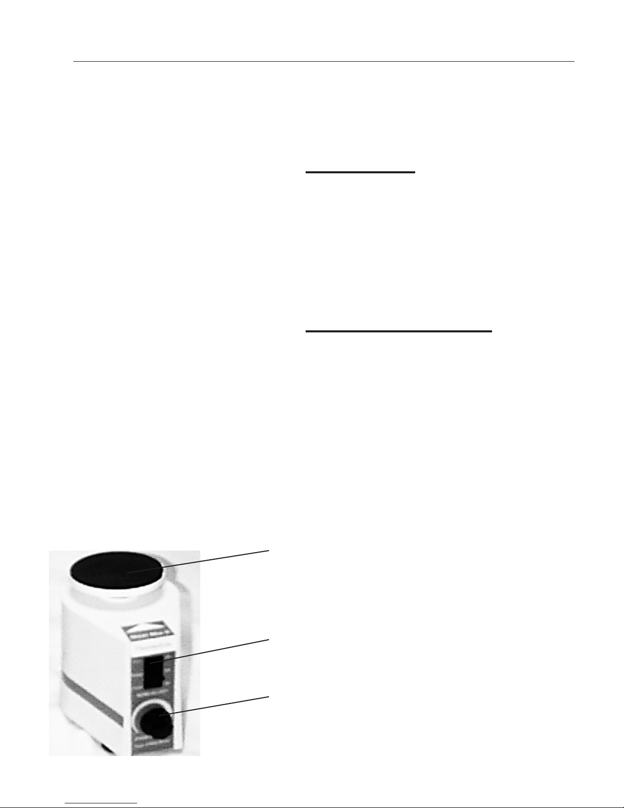
Power Switch: ..................................................................................................................................................7
Speed Control: ................................................................................................................................................7
Maintenance and Servicing ................................................................................................................................8
To Replace the Power Switch: ........................................................................................................................8
To Replace Rheostat (Speed Control): ............................................................................................................8
To Replace Microswitch: ..................................................................................................................................9
To Replace Motor:..........................................................................................................................................10
To Replace Damper Springs: ........................................................................................................................11
To Replace Mixing Surface Disc: ..................................................................................................................12
To Install Single Cup Mixing Head: ..............................................................................................................12
Problem Solving Guide ....................................................................................................................................13
Replacement Parts List ....................................................................................................................................14
Ordering Procedures ........................................................................................................................................14
Exploded View ..................................................................................................................................................15
One Year Limited Warranty ..............................................................................................................................16
Table of Contents