Thermo Scientific Lindberg/Blue M VO Series User manual

f
\
Thermo Fisher Scientific
LindbergIBlue
M
Vacuum Ovens
V0914
I
V01218
I
V01824
Installation and Operating Manual
34598H19
E
11/2011
\
/
Part of Thermo Fisher Scientific
Therrno
SCIENTIFIC

© 2
011
Thermo Fisher Scientific Inc. All rights reserved.
These operating instructions are protected by copyright. Rights resulting thereof, particularly reprint,
photomechanical or digital
post processing
or reproduction, even in part, are only allowed with the written con
sent
of Therm
o
Fisher Scientific Inc.
This regulation does not apply to reproductions for in
-
plant use.
The contents of this operating instructions manual may change at any time and without a
ny prior notice. In case of
conflicting translations into foreign languages the German
-
language version of these operating instructions shall be
binding.
Trademarks
Thermo Scientific is a brand owned by Thermo Fisher Scientific, Inc.
Lindberg Bl
u
e M
®
and a
ll other trademarks
mentioned in the operating instructions are the exclusive property of the
respective manufacturers.
Thermo Fisher Scientif
ic
Inc.
275 Aiken Road
Asheville, NC
28804
USA
Thermo Fisher Scientific Inc.
8
1 Wyman Street
Waltham, MA 02454
USA
Thermo Fisher Scientific Inc. provides this document to its customers with a product purchase to use in the product
operation. This document is copyright protected and any reproduction of the whole or any part of this d
ocument is
strictly prohibited, except with the written authorization of Thermo Fisher Scientific Inc.
The contents of this document are subject to change without notice. All technical information in this document is for
reference purposes only. System con
figurations and specifications in this document supersede all previous
information received by the purchaser.
Thermo Fisher Scientific Inc. makes no representations that this document is complete, accurate or error
-
free
and assumes no responsibility and w
ill not be liable for any errors, omissions, damage or loss that might
result from any use of this document, even if the information in the document is followed properly.
This document is not part of any sales contract between Thermo Fisher Scientific Inc
. and a purchaser. This
document shall in no way govern or modify any Terms and Conditions of Sale, which Terms and Conditions of Sale
shall govern all conflicting information between the two documents.


Laboratory Vacuum
Ovens
6
Operation
.
UP150
Controller(
"
P" Models only)
........................................
8
6.1 Normal ControllerOperation
................................................................
8
6.2 Single Setpoint Operation
..................................................................
9
6.2.1 SettingHigh TemperatureAlarmSetpoint:
...............................................
9
6.2.2 AccessingLocalMode
..............................................................
9
6.2.3 ExitingLocalMode
.................................................................
9
..................................................
6.3 ProgrammingOperation:Entering a Program
9
6.3.1 EnteringProgrammingMode
.........................................................
9
6.3.2 EnteringProgram Parameters
.......................................................
10
6.3.3 RunningaProgram
................................................................
11
.................................................................
6.3.4 EndingaProgram
11
6.3.5 ChangingaProgram
...............................................................
11
6.4 Auto Tuning the UP150 Controller
..........................................................
11
6.5 TemperatureOffsetProcedure
.............................................................
12
6.6 ChangingTemperatureScale Between
C
and
T
..............................................
12
7
Maintenance
.....................................................................
13
7.1 GeneralMaintenance
....................................................................
13
7.2 GasketMaintenance
.....................................................................
13
7.3 DoorAlignment
.........................................................................
13
..................................................................
8
Troubleshooting
14
9
Replacementparts
................................................................
15

Installationand Operation
Laboratory Vacuum Ovens
1
Introduction
The LindbergIBlue
M
VO
Series is a family of laboratory
vacuum ovens designed for drying, curing, outgassing, process
control, and applications which require elevated temperature in
reduced atmospheres or vacuudpurge with non
-
flammable
gases. Refer to Table
1
on page
2
for specifications.
1.1
Features and Benefits
Single setpoint digitalelectronic control (models with suffix
P
have programmablecontrols).
Built
-
in overtemperature protection.
Fully flexible vacuudpurge/release system.
Vacuum system includes inert gas injection valve, fresh air
inlets, vacuum port to exhaust vacuum atmosphere, and
controllable vacuum release vent port.
1.2
Available Door Gaskets
In addition to the standard silicone gasket provided with the
oven, the following gaskets are availablefrom LindbergIBlue
M:
Buna
-
N gasket for use with solvents up to
160°C.
Viton
-
B gasket for applications involving acids.
Refer to Table
7
on page15 for gasket ordering information.

Installationand Operation
Laboratory Vacuum Ovens
1.3
Specifications
Table
1.
Lindbergmlue
M
VO SeriesLaboratory Vacuum Ovens
2
Safety
Considerations
Model
V0914(P)A
VO914(P)C
V01218(P)A
VO1218(P)C
V01824(P)A
VO1824(P)C
V0914S(P)A
V0914S(P)C
V01218S(P)A
VOIZI8S(P)C
V01824S(P)A
V01824S(P)C
WARNING! Do not modify or change system
components. Replacementparts must be OEM.
exact replacement equipment. Modificationor use of
the equipment in a manner other than expressly
intended may cause death or serious injury. This
includes use of user
-
suppliedcomponentsand
materials not specificallydesigned for the oven.
Reconfiguring the controllermay cause death or
serious injury.
LindbergIBiue
M
shall not be liable for any damages,
including incidental and/or consequentialdamages,
regardlessof the legal theoty asserted,including
negligence and/or strict liability.
WARNING1 Before maintainingthis equipment,
read the applicable MSDS (Material Safety Data
Sheets) provided with your oven.
Chamber
9x14~9
(22.9
X
35.6
X
22.9)
12x18x12
(30.5 x 45.7 x30.5)
18 x 24x 18
(45.7
X
61
X
45.7)
9x14~9
(22.9
X
35.6
X
22.9)
12x18~12
(30.5 x 45.7 x30.5)
18x 24
x
18
(45.7
X
61
X
45.7)
WARNING! This unit is not intended for use in
processinghazardous work loads. Fatal injuries and
property damage can result from processing
combustiblevolatile fluids or materials which emit
explosivevapors.
Voltage
120 VAC, 50160
Hz,
Single Phase
240
VAC,
50160
H~,
SinglePhase
120 VAC, 50160
Hz,
SinglePhase
240VAC, 50160
Hz,
SinglePhase
120 VAC, 50160
Hz,
SinglePhase
240
VAC,
50160
H~,
Single Phase
120VAC, 50160
Hz,
SinglePhase
240
VAC,
50160
H~,
SingiePhase
120 VAC, 50160
Hz,
SinglePhase
240VAC, 50160
Hz,
SinglePhase
120 VAC, 50160
Hz,
SinglePhase
240
VAC,
50160
H~,
SinglePhase
Do not use combustible gases in this oven.
DimensionsWx
F
-
B
x
H
Exterior
17.5 x 20 x 24.7
(44.5
X
50.8
X
62.7)
20.5 x 23 x 28.4
(52 x 58.4 x 72.1)
26.3
x
30.4 x34.3
(66.8
X
77.2
X
87.1)
17.5 x 20 x 24.7
(44.5
X
50.8
X
62.7)
20.5 x 23 x 28.4
(52 x 58.4 x72.1)
26.3 x30.4 x 34.3
(66.8
X
77.2
X
87.1)
Avoidcombustible products which generate toxic or
hazardousvapor or fumes. Work should only bedone
in a properly vented environment.
Exterior
Enameled
Steel
Stainless
in.
(cm)
Shipping
(Approximate)
27.5
x
30 x 34.7
(69.8
X
76.2
X
88.1)
30.5 x33 x 38.4
(77.5 x 84
x
98)
36x41x45
(91.5
X
104.1
X
114.3)
27.5 x30 x 34.7
(69.8
X
76.2
X
88.1)
30.5 x 33 x 38.4
(77.5 x 84 x 98)
27.5 x 30 x 34.7
(69.8
X
76.2
X
88.1)
Before using, user shall determinethe suitabilityand
integrity of the product for the intendeduse and that
the unit has not been altered in any way. User
assumes all risk and liability whatsoevertherewith.
Heater
Power
(kw)
1.05
.55
1.55
1.05
.55
1.55
Shipping
Weight
Ibs
(kg)
150
(68)
250
(114)
325
(148)
150
(68)
250
(114)
325
(148)

Installationand Operation
Laboratory Vacuum Ovens
Figure
1.
Vacuum and Gas Connections
114
"
Gas
inlet
07
vacuum por~
114" Ventport
I
Vent Gas Vacuum
.
1
-
.
-
-
1
-
I
1
-
-
1
-
.
1
-
I
-
-
-
-
.
-
CAUTION! Thisproductcontainsfiberglasswoolor
other refractories which can result in the following:
1
"
NPTvacuumport
-
May be irritatingto skin, eyes, and respiratorytract.
Maybe harmfulif inhaled.
Possible cancer hazard based on tests with
laboratolyanimals. Animal studies to date are
inconclusive. No human exposurestudieswith this
product have been reported.
-
-
-
-
-
-
I
WARNING! Before maintainingthis equipment,
read the applicableMSDS (MaterialSafety Data
Sheets) at the back of this manual.
Dl
.
-
1
I
-
-
1
1
.
1
-
-
Power cord
?,-;
-
.
Overtemperatureresetbutton
WARNING! When installing, maintaining, or
removingthe refractoryinsulation. the following
precautions will minimizeairborne dust and fiber:
Keeppersonnel not involvedin theinstallationout of
the area.
Use a good vacuum to clean area and equipment.
Use a dust suppressantif sweepingis necessary.
Do
not
use compressedair.
Use disposable mask suitable for nuisance dust.
Wear long sleeve clothing, gloves, hat, and eye
protection to minimize skin and eye contact. Do not
wear contact lenses.
Thoroughly wash self after work is complete.
Launder work clothing separate from other clothes
and thoroughly clean laundering equipment after
use. If clothing contains a large amount of dust
andlor fiber, dispose of rather than clean.
Promptlyplace used fiberglass parts and dust in
plastic bags and dispose of properly.

Note:
Since
the
front
panel
display
reads
gauge
pressure
the
value
is
relative
to the
local
atmospheric
pressure.
Use
in
a
location
with
reduced
atmospheric
pressure
will
result
in
the
gauge
displaying
diminished
vacuum
levels.

Installationand Operation
Laboratory Vacuum Ovens
4
Start
Up
Table
2.
UT150 Parameter Functions
CAUTION! Observe the following precautions
when operating the oven:
Wear protectiveeyeware.
Wear protectivegloves.
Use tongs to insert and remove oven load.
Do not allow the load to touch the oven walls.
CAUTION! Do not attempt to operate the oven
above the maximum rated temperature of
260°C.
Operation above
260°C
can cause damage to the
oven.
4.1
Oven Start Up
To start the oven,complete thefollowing steps:
1.
Turn
on main power switch. Wait until the controller runs
initial diagnostics.
2.
Verify the vacuum pump connection (see Section 3.3 on
page
4).
3. Select the desired setpoints (refer toSection 5.3 on page
6
if
you have a UT150 controller, Section
6
if you have a UP150
controller).
5
Operation
-
UT150
Controller
The oven temperature controller is configured and tuned at the
factory to function well for most applications. Occasionally, it
may be advisable to configure the temperature controller
differently tosuita particular working environment or process.
Table
3.
Pushbutton Keypad
CAUTION! Before reconfiguringthecontroller,read
this chapter and the
"TI50
operation manual.
Reconfiguring the controller can change the unit
SC
dr
characteristicsand design parameters, which can
hamper performance and make the equipment
dangerous to use.
SuperControl
Directheverseaction
This chapter provides brief instructions on how to perform the
following configuration changes:
Setting the temperature
Setting the OvertemperatureProtection Temperature
Changing between celsius and fahrenheit
Setting the ramp to setpointtime
Autotuning the controller
Detailed instructions on configuring the temperature controller
arefound in the UT150 operation manual.
5.1
Normal Controller Operation
The Temperature Controller senses the chamber air temperature
of theoven (the
PV,
or process value) and supplies the heat
necessary to achieve the desired setpoint. The controller includes
an
LED
display and a pushbutton keypad. Refer toTable
2
and
Table3 for lists of displayed parameters and keypad functions.
Button
A
v
Function
Pressingand holdingthe SETIENTfor three seconds
advancesthe displayto the OperationParameters
Menu.
Whilein the OperationParametersMenu, use
SETIENTtomovefromoneparametertothenext, and
to register changesyou have made in setpointand
parametervalues.
HoldingSETIENTfor threesecondsexitseither the
Operationor Setup Parametersmenu.
Use the Up Arrowbutton to increasethe temperature
setpointdisplay andtochangeparametervaluesin the
Operationand SetupParametermenus. Whenever
you changethe value of a setpointor parameter, the
decimalpoint flashesto remindyou to registerthe
changedvalue with SETIENT.
Use the Down Arrow buttonto decreasethe
temperaturesetpointdisplay andto changeparameter
valuesin the Operationand Setup Parametermenus.
Wheneveryou changethe value of a setpointor
parameter, the decimalpoint flashesto remindyou to
registerthe changedvalue with SETIENT.

Installationand Operation
Laboratory Vacuum Ovens
5.2
Setting the Temperature
To set the temperature to the desired setpoint, complete the
following steps:
1. Press
a
or
7
until the desired setpoint is indicated on the
bottom line of the display.
2. Press
SETIENT
to register the new setpoint.
5.3
Setting the OvertemperatureProtection(OTP)
Temperature
The high limit alarm system with the temperature controller
disables theheater output. To set the alarm on the temperature
controller (typically 5°C above the desired main temperature
setpoint), complete the following steps:
1. Press and hold
SETENT
for 3 seconds, until
A1
is displayed
on the upper line.
2. Press
A
or
V
until the desired overtemperature limit
setpoint shows onthe bottom line of the display.
3. Press
SETENT
to register the new overtemperature alarm
setpoint.
4. Press and hold
SETENT
for 3 seconds to return to the normal
display.
5.4
Changing Between Celsius and Fahrenheit
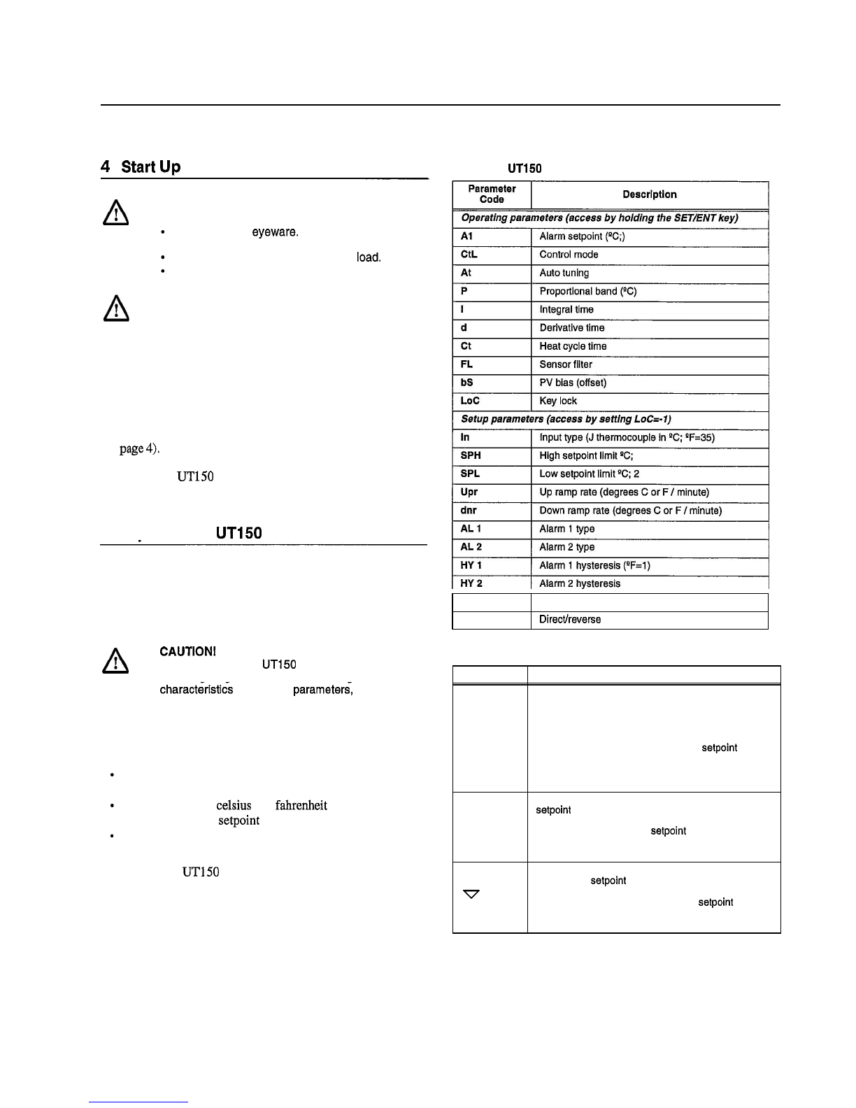
The controller isfactory
-
set to operate with degrees Celsius. To
change the display modes and parameter settings to the
Fahrenheit scale, you will need to change the Input Type
parameter
In
and also the values of various scale
-
dependent
parameters. If during this procedure the buttons are inactive for
more than two minutes, the controller will return to the standard
display.
To change from Celsius to Fahrenheit:
1.With the controller operating, access the Operating
Parameters menu by pressing and holding
SETIENT
for3
seconds.
2. Press and release
SETIENT
repeatedly until theupper display
reads LoC.
3. Press
V
until the displayed value of LoCis
-
1; then press
SETIENT
to access the Setup Parameters menu (refer to
Table 2 on page
5).
4. The first setup parameter displayed is Input 'Qpe (In). Press
tochange its value from
5
to 35. After making this
adjustment (andall following parameter adjustments) be sure
topress and release
SETIENT
again to register the change.
5. Press and release
SETIENT
to advance to theSPH parameter
and change its value to 500.
6. Press and release
SETIENT
to advance to theSPL parameter
and change its value to 32.
7.
Press and release
SETENT
to advanceto the HY1 parameter
and change its value to
1.
8.
Press and hold
SETENT
for 3 seconds to exit theSetup
Parameters Menu.
9.
Press and hold
SETIENT
for 3 seconds toenter the Operating
Parameters Menu anddisplay the A1 parameter.
10.Usethe Abutton to set the
A1
parameter to the desired
overtemperature limit in OF.
11. Press and release
SETIENT
to advanceto the P parameterand
change its value to 16.2.
12. Press and hold
SETIENT
for 3 seconds to exit theOperating
Parameters Menu.
13. The new temperature units are now effective. Follow the
instructions inSection 5.2 to reset the temperature setpointin
"
E
14. Apply the OF label over the "C label on the control panel.
5.5
Setting the Ramp to SetpointRate
The Ramp Ratefeature allows the chamber to beheated or
cooled at any rate slower than the maximum capability of the
unit. To fine tune ramp rates, you may need to test using loads
with similar mass and thermal properties to loads you intend to
usein oven applications.
To set the ramp to setpoint time, complete the following steps. If
during this procedure the buttons are inactive for more than two
minutes, the controller will return to the standard display.
1.
With the controller operating, press and hold
SETIENT
for
3
seconds to enter the Operating Parameters menu.
2. Press and release
SETIENT
until the LoC parameter is on the
upper display.
3. Press the down arrow button toshow '-I1,and press
SETIENT
once to enter theSetup Parameters menu.
4.
Press and release
SETIENT
until the Upr parameter is on the
upper display.
5. Press the arrow buttons to select the new Up Ramp Rate
value, in OC per minute or OF per minute, or 'OFF'. Press and
release
SETENT
to register the value change.
6. Press and release
SETIENT
until the dnrparameteris on the
upper display.
7.
Press the arrow buttons to select the new Down Ramp Rate
value, in OC per minute or OF per minute, or 'OFF'. Press and
release
SETIENT
to register the value change.
8.
Press and hold
SETENT
for three seconds to exit the Setup
Parameters menu.
9.
The new Ramp Rates are now effective.
10. Follow theinstructions inSection 5.2 toreset thetemperature
setpoint.
Note:
The ramp rate begins when the
SET/ENT
buttonis
pressedafter the target setpoint is selected. The setpoint
display on the controllerwill show the changing setpoint
at the selected ramp rate.
To view the target setpoint during theramp rate,press andrelease
an arrow button. Thelower display will show the setpointnext to
the selected target setpoint. Return to the ramping setpoint
display by pressing and releasing the other arrow button.

Installationand Operation
Laboratory Vacuum Ovens
5.6
Auto Tuning the Controller
Factory settings are provided for general purposes, but your
process can beenhanced through the auto tunefeature. For a
given process temperature and product load, auto tuning
maximizes theperformance of the chamber by operating with the
quickest response and minimal temperature overshoot.
To auto tune the controller.
1.
Load the chamber with materials that have the same mass
and thermal characteristics as a typical product load.
2.
Operate the chamber to the process temperature.
3.
Press and hold
SETlENT
for
3
seconds to display the A1
parameter of the Operating Parameter menu.
4.
Press and release
SETIENT
to show the At parameter.
5.
Press and release the arrow buttons to show on in the lower
display.
6.
Press
SETIENT
once to enter the auto tune mode and exit the
Operating Parameters menu.
The controller will cycle three times through a heating and
cooling pattern, measuring the characteristics of the load and
chamber temperature controls. During the auto tuning, At will
alternately flash with the measured temperature
(PV)
to indicate
that theauto tuning is in progress. Thelengthof timefor the auto
tune varies with the load, chamber size and temperature selected.
The auto tuneis completed when the regular display of the
measured temperature is shown. The chamber should now
operate to the process temperature with the given product load,
with the quickest response and minimal temperature overshoot.
If the process temperature or load changes significantly, another
auto tune session may be necessary to optimize the chamber
performance.

Installationand Operation
Laboratory Vacuum Ovens
6
Operation
-
UP150 Controller
Table
4.
UP150 Parameter Functions
("P"
Modelsonly)
RUN
m
m
HOLD
Table5. Pushbutton Keypad
Figure
2. UP150
Control Panel
parameter
'Ode
The oven temperature controller is configured and tuned at the
factory to function well for most applications. Occasionally, it
may be advisable to configure the temperature controller
differently to suit a particular working environment or process.
CAUTION1 Before reconfiguringthe controller,read
this chapter carefully. Reconfiguringthe controllercan
change the unit characteristics and design
parameters, which can hamper performanceand
make the equipment dangerous to use.
Fag:'y
Value
For more detailed instructions, refer to the Yokogawa UP150
manual.
Description
Operatingparameters(access
by
holding the SETENTkey)
6.1
NormalController Operation
HoLd
AdV
CtL
At
P
I
d
Ct
FL
bS
LoC
The Temperature Controller senses thechamber air temperature
of the oven (the
PV,
or process value) and supplies the heat
necessary to achieve the desired setpoint. The controller includes
an
LED
display and a pushbutton keypad. Refer to Table
2
and
Table
3
forlists of displayed parameters and keypad functions.
The UP150 controller will accept a single program of up to
16
segments. This controller includes an automatic tuning feature
and
"
Super
"
control to improve the performance. Refer to the
UP150 manual for detailed information.
OFF
OFF
Pid
OFF
32.4
1384
346
1
OFF
0.0
0
ProgramHold
Segment Advance
Controlmode
Auto tuning
Proportionalband QF=ll)
Integraltime
Derivativetime
Heat cycletime
Sensor filter
PV bias (offset)
Key lock
Setup parameters(access
by
setting LoC=-1)
In
SC
Button
@
a
v
Function
Pressing and holdingthe SETIENT for three seconds
advances thedisplay to the OperationParameters
Menu.
While inthe OperationParameters Menu, use
SETIENTto movefromoneparameterto thenext, and
to register changes you have made in setpointand
parameter values.
HoldingSETIENTfor three seconds exits eitherthe
Operationor Setup Parameters menu.
Use the Up Arrow buttonto increasethe temperature
setpointdisplayandtochangeparametervaluesinthe
Operationand Setup Parameter menus. Whenever
you changethe value of a setpointorparameter, the
decimalpoint flashes to remindyou to register the
changedvalue with SETIENT.
While in operatingmode, pressing this key stops
(resets) program operation.
Use the Down Arrowbutton to decreasethe
temperaturesetpointdisplayandto changeparameter
valuesin the Operationand Setup Parameter menus.
Wheneveryou change the value
of
a setpointor
parameter, the decimalpoint flashesto remindyou to
registerthechangedvalue withSETIENT.
While in operatingmode, pressing this key starts
(runs) a program
5
ON
Inputtype
(J
thermocouplein *C; *F=35)
Super function

Installation and Operation
Laboratory Vacuum Ovens
6.2
Single Setpoint Operation
The following sections describe how to operate the controller in
single setpoint (local) mode. Use this mode when you only need
to run the oven with a specific setpointand do not require a
programmed sequence of steps.
6.2.1
SettingHigh TemperatureAlarm Setpoint:
1. Press and HOLD for three seconds the 'SETENT' button to
display "modE rES".
2.
Press and release the 'SETENT' button to display "PrG
0".
3.
Press the 'UPIRESET' Button toshow the lower display
value of
"
1
"
.
4.
Press and release the 'SETENT' button to select this new
value and advance to the
"
SSP
25
"
display.
5.
Press and release the 'SETENT
"
button until the High
Temperature Alarm Setpoint value is displayed as
"
Al
"
.
6.
Select an alarm setpoint 10°C above the target setpoint to be
selected.
7.
Press and release the 'SETIENT' button to place this new
value in the controller memory.
8.
Press andHOLD for three seconds the 'SETIENT' button to
exit this menu.
6.2.2
Accessing Local Mode
1.
Press and hold for three seconds the 'SETIENT' button to
display "modE rES".
2.
Press and release the 'UP' button twice to select the display
"modE LCL,".
3.
Press and release the 'SETENT' button once to select Local
Mode. This selection causes the red indicator to illuminate
beside
"L"
onthe control panel.
4.
Use the
'UP'
and 'DOWN' buttons to select the desired
operating temperature setpoint.
5.
Press and release the 'SETENT' button once to register the
setpoint value.
6.
The display will then show measured temperature in the
upper display, thepresent temperature setpoint in the lower
display.
7.
This display and thebuttons will remain activeas long power
continuesto the control module. Power interruptions will
cause thecontroller to enter reset or standby mode in which
no actions are made to operate the heating equipment.
You may use the arrow buttons to adjust the setpoint (lower)
valueto beadjusted in this display mode. The 'SETJENT' button
will register setpoint value changes,until these values are
changed again.
6.2.3
ExitingLocal Mode
To exit Single Setpoint or Local Mode and turn off the energy to
the heaters:
1.
Press and hold for three seconds the 'SETENT' button to
display "modE LCL
"
.
2.
Press and release the 'DOWN' button twice to select the
display "modE rES".
3.
Press and release the 'SETIENT' button once to select the
Reset Mode.
This selection causes the red indicator to extinguish beside
the display label
"
L
"
that had indicated theLocal Mode.
4.
This will change the display showing the measured
temperature in the upper display, with the lower display
showing the Start SetPoint (SSP) temperature setpointof the
program.
6.3
Programming Operation: Entering a Program
This section describes how to enter a simple program that is
designed to:
direct the controller to ramp to a higher temperature;
stabilize;
ramp to a lower
-
temperature;
end with
an
indefinitedwell.
If you intend to use the program features of the controller, it is
advisable to go through all the steps in this sample program to
familiarize yourself with the elements of programming mode.
Note:
If
the controller buttonsare NOTpushed for
2
minutes,
the controllerwill return to the regular operator
mode/menu.
6.3.1
Entering ProgrammingMode
To access the programming menu:
1.
Make sure the indicators beside
"
RUNand
"L"
on the
controller faceare off. If either indicator is on, press and hold
the 'SETENT' buttonuntilthedisplay shows 'modE'. Select
'rES' in the lowerdisplay with the 'arrow' buttons. Press and
release the 'SETENT' button once.
2.
Press the 'SETENT' button for
3
seconds todisplay "modE
in the upper display and "rES" Reset)in the lower display.
3.
Press and release 'SETENT' until "LoC" is displayed. Make
sure the display below "LoC" is
"0"
(zero). If itis not
"0",
use 'DOWN ARROW' to select
"0"
and press and release
"
SETENT' button to register the change to
"0".
4.
Press and release the
"
SETENT' button until "PrG" is
displayed.
5.
At "PrG display, press the 'UP ARROW' to make the lower
display
"
1
"
.
6.
Press and release the 'SETIENT' button once to enter the
programming menu.

Installationand Operation
Laboratory
Vacuum
Ovens
6.3.2
EnteringProgram Parameters
Thefirst display is theStart Set Point parameter,shown as
"
SSP
in the upper display. The value assigned to SSP is usually the
current room temperature, 25°C.
On the next pageis
an
illustration of the program profile and a
tableof the parameters entered.
Basic Ramp and
Dwell
Parameters:
1. Use the arrow buttons to select
"
25
"
in the lower display,
then press and release the 'SETENT' button twice to enter
this new value and to advance to the "StC" display.
If the value for
"
SSP
"
is correct and does not need to be
changed, press and release the 'SETENT' button once to
advance to the "StC" display.
2.
Next is the Start Code parameter, shown as "StC" in the
upper display. The value assigned to StCis usually
"0".
This
will instruct the program to follow the Start SetPoint. Press
the SETENTbutton to advance to the next display.
3. The next parameter, "SPl", is the first setpoint value that is
desired in thechamber and is normally a ramp segment.
Select this target temperature setpointvalue with the arrow
buttons then press and release the 'SETIENT' button twice to
enter this value and to advance to the "tM1" display. If the
value for "SP1" is correct and will not be changed, press and
release the 'SET/ENT' button once to advanceto the "tM1"
display.
4.Thenext parameter, "tMl", represents the first time period
for the unit toreach the target temperature setpoint selected
in "SP1". This selection can be a value ranging from 0.00 to
99.59, which represents hours and minutes. Select this time
value with the arrow buttons and enter it by pressing and
releasing the 'SETENT' button twice.
5. Press and release the 'SETENT' button to advance to the
next display of "SP2", this is normally thedwell segment.
Select thesame target setpointtemperature value as "SP1"
with the arrow buttons. Press and release the 'SETIENT'
button twice to enter this value and to advance to the next
display.
6. Thenext parameter, "tM2", represents thesecond time period
used to maintain or dwell at the target setpointselected in
"
SPY. This selection can be a value ranging from 0.00 to
99.59, which represents hours and minutes. Select this time
value with the arrow buttons and enter it by pressing and
releasing the 'SETENT' button twice.
7.
Next, "SP3" is the third setpoint value desired in the
chamber. Select this target temperature setpointwith the
arrow buttons and press and release the 'SET/ENT' button
twice to enter this value and to advance to the "tM3" display.
If this value is correct and not changed, press and release the
'SETENT' button once to advance to the "tM3" display.
8.
"tM3" represents the third time period for the unit to reach
the target setpoint selected in "SP3". This selection can be a
value ranging from0.00 to 99.59, which represents hours and
minutes. Select this value with the arrow buttons and enter it
by pressing and releasing the 'SETIENT' button.
9. The next parameter, "SP4" is normally the dwell segment.
Select the same target temperatureas "SP3" with the arrow
buttons, then press and release the 'SETENT' button twice
to enter this new value and to advance to the next display.
Additional Program Parameters
"
10.Thenext parameter displayed is "tM4". Select a lower
display value of
"OFF"
with the 'arrow' buttons, then press
and release the 'SETENT' button twice to enter this value
change and advance to the next display.
11.The next display shows "EV1" in the upper display. The
lower value should always be
"0"
(zero). Press and release
the 'SETIENT' button once to go to the next display.
12."ALlWshould always have a lower value of
"
9
"
.
Press and
release the 'SETIENT' button once to advance to the next
display.
13.Thenext parameter, "Al", is used to select the high
temperaturealarm trip setpoint. Use the 'arrow' buttons to
select a value 10°C (or 20°F) HIGHER than the
highest
target setpointto be used. Select the High Temperature
Alarm value with thearrowbuttons then press and release the
'SETIENT' button twice toenter this new value and to
advanceto the
"
HY
1
"
display. If the value for
"
Al
"
is correct
and not changed, press and release the 'SETIENT' button
once to advance to the "HY1" display.
14."HY17'is used to select theamount of temperature change
below the high temperature alarm setpoint where the alarm
relay will reset. This value is usually "1". Select
"
1
"
with the
arrow buttons and press the 'SET/ENT' button six times to
enter thecorrect value and advanceto the
"
JC
"
display. Orif
the value is correct, press the 'SETLENT' button five times to
advance to the
"
JC
"
display.
15.Forthe parameter displayed as
"JC",
select
"
1
"
with the
arrow buttons, then press and release the 'SETENT' button
twice to display
"WTZ".
Selecting the valueof
"
1
"
will cause
the program to hold the setpoint at this last segment. A value
of
"0"
would cause the program to reset and stop running the
program and stop the power to the heaters. A value of
"
2
"
will cause the program to repeat 'continuously'.
16.Whenthe display shows
"WTZ",
select a lower display
value of "OFF" with the 'arrow' buttons. Press and HOLD the
'SETENT' button for 3 seconds to return to the Reset or
standby display.
This concludes the steps required to enter a typical ramp
-
and
dwell program.

Installation and Operation
Laboratory Vacuum
Ovens
6.3.3 Running a Program
6.4
Auto Tuningthe
UP150
Controller
To run a program such
-
as the one outlined above, press and hold
the 'DOWNIRUN' button making the 'RUN' indicator
illuminate. At theend of this program the 'HLD' (hold) indicator
isilluminated to indicate this program is in the indefinite dwell at
thelast target temperature. This hold indicator is caused by the
"
JC
"
selection of "I", while the
"
JC
"
selections of
"0"
or
"
2
"
will
not illuminate the 'HLD' (hold) indicator.
6.3.4 Ending a Program
To end a program while in the 'RUN' or 'HLD
"
(hold) mode,
press and hold the 'UPIRESET' button to turn off the current
program and extinguish the 'RUN' or 'HLD' indicator.
Turning off the unit's power will also stop the program. When
power is restored, thecontroller is in the Reset or standby mode
with no power to the heaters.
Note: The programmer/controller will not operate the unit's
heaters (tochange or maintain a temperature) unless
there is
a
program running ora single setpoint value is
selected in the Local Mode.
6.3.5 Changing a Program
To make changes ONLY to the target temperature and segment
length times for simple program operation, follow these steps:
1. Make sure the indicators beside
"
RUN
"
and
"
L,
"
on the
controllerface areoff. If eitherindicator is on, press and hold
the 'SETENT' button until thedisplay shows 'modE'. Select
'rES' in thelowerdisplay with the 'arrow' buttons. Press and
release the 'SETENT' button once.
2.
Press the 'SETIENT' button for
3
seconds todisplay "modE
in the upper display and "rES" in the lower display.Press and
release 'SETENT' repeatedly to display "LoC". Make sure
the value below
"LoC"
is
"0"
(zero). If it is not
"O",
use
'DOWN' arrow to select
"0"
and press and release
"
SETENT
"
button to register the change to
"0".
3.
Press and release the 'SETJENT' button once to show "PrG"
on the upper display.
4.
Press the
'UP'
arrow to make the lower value
"
1
"
.
5.
Press and release 'SETIENT' button twice to display "SP1".
Using the arrow buttons to revise the target setpoint.
6.
Press and release 'SETENT' button twice to display
"
tml
"
.
Using thearrow buttons to revise the segment timelength
needed toget to the target setpoint 'SP1'.
7.
Press and release 'SETENT' button to display other
setpoints and segment time lengths. Use the arrow buttons to
change the temperaturesetpoints and time lengths. Press and
release the 'SETIENT' button to register any new values.
8.
Press and HOLD the 'SETENT' button for
3
seconds to exit
the program menu and return to the reset or standby display.
Auto tuning maximizes the performance of the chamber at a
selected temperature with the product load's characteristics, by
operating with the quickest response and minimal temperature
overshoot.
Factory settings are for general purposes, but your process can be
enhanced through the auto tune feature. To obtain this maximum
performance, follow these steps to auto tune thecontroller.
1. Load the chamber with materials that have the same mass
and thermal characteristics as an actual product load.
2.
Operate the chamber to the process temperature.
3.
Start the Auto Tune: Press and hold the 'SETtENT' button
for three seconds to display the "modE" parameter of the
Operating Parameter menu.
4.
Press and release the 'SETENT' button five times to
advance to the
"
At
"
parameter.
5.
Press and release the
'UP'
arrow button to show
"
on
"
in the
lower display.
6.
Press the 'SETtENT' button once to enter the auto tune mode
and exit the Operating Parameters menu.
7.
The controller will cycle three times through a heating and
cooling pattern, measuring the characteristicsof the load and
chamber temperature controls. During the auto tuning, 'At'
will alternately flash with the measured temperature (PV)
display to indicate that the auto tuning is in progress. The
length of time for theauto tune varies with theload, chamber
size and temperature selected.
8.
Theauto tuneis completed when the regular display of the
measured temperature is shown without the
"
At
"
value
flashing. The chamber should now operate to the process
temperature with the given product load, with the quickest
response and minimal temperature overshoot.
9.
If the process temperature or load changes significantly,
another auto tune session may be necessary to optimize the
chamber performance.
To interrupt the auto tunebefore it is completed, simply turn off
the power to the controller and unit. When the power is restored
the auto tune will not be operating.

Installationand Operation
Laboratory Vacuum Ovens
6.5
TemperatureOffset Procedure
The purpose of this procedure is to create an offset in the
displayed temperature measurement for the Yokogawa model
UP150 temperature controller.
1. Operate the oven chamber to your normal stable temperature
setpoint, with an independent temperature measurement
device located in the center of the chamber. The controller
will be 'running' the program or operating in the local mode
to maintain the temperature.
2. Note any difference in the controller's measured temperature
(upper value) and the independent measurement. If a
differenceof greater than 1°C is noted proceed with the
following steps.
3. Press and hold the
"
SETENT
"
button for 3 seconds to
display "modE".
4. Verify the button lockout parameter will give access to make
thisdisplay offset. Press and release the
"
SETENT
"
button
twelve times to display "LoC". The value 0 (zero) displayed
will give full access and is necessary to make the display
offset changes desired. If the value displayed is 1 or 2, use
the
"
down arrow
"
button to make 0 (zero) and press and
release the
"
SETENT
"
button to register this change.
5. Press and release the
"
SETENT
"
button twelve times to
display "bS" and the current offset value.
6. Select the offset value with the arrow buttons that is needed
to make this controller display correctly.
For example, if the independent measurement is 253"C, the
controllerTemperature measurement display shows 250°C,
and the current controller offset (bS) is
-
2, then make the
controller display offset "+I"
[(+3 needed offset)
+
(
-
2 current offset)
=
(+1 new offset)].
7.
Press and release the
"
SETENT
"
button once to register this
new offset value. Press and hold the
"
SETENT
"
button for 3
seconds to exit this controller menu.
8. Operatethecontroller to thesame temperature to stabilize the
chamber to check for any further variations between the
controller and theindependent measurement. Repeat steps
2
-
7
as necessary.
9.
This completes the display offset procedure for the
Yokogawa model UP150 temperature controller.If the button
lockout parameter "LOPwas originally on a value of 1 or 2,
repeat steps 3
&
4 to return to this original value.
ContactTechnical Service at 1
-
800
-
438
-
4851 if you have any
questions.
6.6
ChangingTemperatureScale Between
'C
and 'F
To change the temperature scale in the UP150 controller to
operate on
OF
instead of the factory setting of
"C,
or from
OF
to
"C,follow these steps.
These changes will alter the controller input type and associated
scale
-
dependant parameters,
AND
ERASE
the storedprogram
to defaultvalues.
Please document the stored program in the
controller
BEFORE
proceeding.
1.
Makesure the indicators beside
"
RUN
and
"L"
on the
controller face are off. If they are on, press and hold the
'UP/RESET' button until the RUN or L indicators are off.
2. To access the Operating Parameters menu, press and HOLD
the 'SETENT' button for at least 3 seconds to display
"modE".
3. Press and release the 'SETENT' button until the display
shows
"
LOC
"
in the upper display. Make sure the value
below "LoC" is
"0"
(zero). If it is not
"0"
use 'down arrow'
to make
"0"
and press and release
"
SETENTbutton to
register change to
"0".
4. At "LoC" display, press the 'down arrow' to make the lower
value
"
-
1
"
.
5. Press and release the
"
SETENT' button to enter the Setup
Parameters menu and show
"
In
"
on the upper display and a
numerical valuein the lower display.
6. See table below for the STANDARD values for this
parameter and the others needed in the following steps.
7.
Select the appropriate value for the
"
In
"
parameter. Press the
'UP' or 'DOWN' arrow buttons to make the lower display to
the new value, then press and release the 'SETENT' button
TWICEto register the new value and advance to the next
parameter.
8.
"
SPH
"
is the next parameter displayed. Select and enter the
new value, then press and release the 'SETENT' button
TWICE.
9.
"SPL" is the next parameter displayed. Select and enter the
new value, then press and release the 'SETENT' button
ONCE.
10.Pressand HOLD the 'SETENT' button for at least 3
seconds to exit.
11.Pressand HOLD the 'SETtENT' button for at least 3
seconds to enter the Operating Parameter menu and show
"modE" in theupper display.
12.Pressand releasethe 'SETENT' button until the upper
display shows
"
P
"
.
Select thevalueinthe table and adjust the
lower display accordingly. Press and release the 'SETtENT'
button TWICE.
13."I" is the next parameter displayed. Select and enter the new
value, then press and release the 'SETENT' button TWICE.
14,"d" is the next parameter displayed. Select and enter the new
value, then press and release the 'SETENT' button ONCE.
15.Press and HOLD the 'SETENT' button for at least 3
seconds to exit.
16.Reenter or create a program using the new temperature
scale.
The P, I and
D
parameters may bealtered through auto tuning
(refer toSection 6.4 on page 11).
If during this procedure the buttons are inactive for more than
two minutes, thecontroller will return to the standard display.

Installationand Operation
Laboratory Vacuum Ovens
7
Maintenance
7.1
GeneralMaintenance
CAUTION!
Maintenance shouldonly be performed
by trainedpersonnel.
WARNING!
Disconnect oven from main power
A
beforeattemptingany maintenance to oven or its
controls.
CAUTION!
Thisproductcontainsfiberglasswoolor
otherrefractorieswhich can result in the following:
May beIrritatingto skin, eyes, and respiratotytract.
May be harmfulif inhaled.
Possiblecancer hazardbased on tests with
laboratory animals. Animal studies to date are
inconclusive.No human exposure studies with this
producthave been reported.
WARNING!
Beforemaintainingthisequipment,read
A
the applicableMSDS (MaterialSafety Data Sheets)
provided with thisunit.
WARNING!
When installing, maintaining, or
A
removingthe refractoryinsulation,the foliowing
precautionswill minimizeairbornedust and fiber:
Keep personnelnotinvolvedin the installationout of
thearea.
Use
a
goodvacuum to clean area and equipment.
Use
a
dustsuppressantif sweepingis necessaly
Do
not
use compressed air.
Use
disposable
mask suitable for nuisance dust.
Wear longsleeveclothing,gloves, hat, and eye
protectionto minimizeskin and eye contact. Do not
wear contact lenses.
Thoroughlywash self after work is complete.
Launderwork clothingseparate from other clothes
andthoroughlycleanlaunderingequipment after
use. If clothinacontainsa larae amountof dust
andlorfiber, $spose of ratheFthanclean.
Promptly place used fiberglassparts and dust in
plastic bags and dispose of properly.
WARNING!
Disconnect oven from main power
A
beforeattemptingany maintenance to oven or its
controls.
Regularmaintenanceisrequiredto keep the ovenrunningat
optimumlevels.
1.
Cleantheoveninterior as necessary with acetone, alcohol,or
ether.
WARNING!
Whenusingcleaningmaterials, follow
A
ail precautionsiistedon the cleaningcontainers.
Alwaysuse cleaningmaterialsInwellventilatedareas
as inadequateventilationcan be fatal.
Note:
Frequencyof cleaning depends on the oven workload.
If
the oven becomes contaminated, the ultimate vacuum
level will not be attained.
2.
Checkhoseconnectionsfor leaks weekly.
3.
Check the vacuumpump oillevel.
4.
Check thecondition ofthe vacuumpumpoil.Replacetheoil
if
itis contaminated.
7.2
Gasket Maintenance
WARNING1
Disconnectovenfrom main power
A
beforeattemptingany maintenance to oven or its
controls.
Thedoor gasketisdesignedfor easy removal andinstallation.
This gasket may comeoffwhenthedoor
is
openedafterhigh
temperatureoperationor processingofworkloadscontaining
resin. To prolonggasketusage, clean the oventoremoveany
resin.
7.3
Door Alignment
A
WARNING!
Disconnectoven from main oower
beforeattemptingany maintenanceto oveh or its
controls.
The ovenmay not pump downproperly
if
thedoorisout of
alignment. To realign theovendoor, completethefollowing
steps:
1.
Lay theovenonits back.
2.
Loosentop andbottomhinges.
3.
Square thedoor. Check that theglass comes
in
contact with
thegasket.
4.
Place asmallamount ofpressure(approximatelyonepound)
onthehinges.
Note:
This pressure is required so that the door seals when
closed. The glassfloats on springs to achieve a complete
seal.
5.
Tightenthehinges.
6.
Pump the oven down.

8
Troubleshooting
WARNING!
Troubleshooting procedures involve working with highvoltages which can cause injury or death.
Troubleshootingshould only be petformedby trainedpersonnel.
This section
is
a
guideto troubleshootingovenproblems.Refer to Table
6
for troubleshootingprocedures.
Table
6.
Troubleshooting
Problem
Oven shelveswarp anddiscolor.
Door gasketcomes off.
Systemultimate pressureishigh.
No vacuumin oven.
Pump stalls.
Long dryingtime.
Probable Causes
Oventemperatureis above 260°C.
Gasket is damagedfromhigh temperature
operationor fromresin damage.
Ovenis contaminated with high vapor
pressurematerial.
Pump oilis contaminated.
Leaks invacuum piping orports.
Vacuumpump seal is worn.
Dischargevalveis worn.
Internalpartsare worn.
Vacuumvent valve isopened.
Ovendoes not pump down properlydue to
misaligneddoor.
Power to pump is off.
Use of extensioncord results in insufficient
amperage.
Pump isdamaged.
The discharge line is blocked.
No pump oil or lostviscosity(overheating).
Thepipingis too narrow.
The
distance
between
the
pump
and
the
oven is too large.
Solution
Do not operatethe oven above 260%.
Do notOperate the oven above 260°C.
Clean oven to remove resin.
Clean the oven. Refer to Section7.1 on page
13.
Changethe oil. Use inlet vapor trap andlorgas ballast.
Check forleaksin vacuumline, oven port, door.
Replace shaft seal.
Replace valve.
Installnew vanes.
Closevent valve.
Realignthe door. Refer to Section
7.3
onpage
13
for
realignment information.
Check the power switch andoutlet.
Movethe oven closerto power source and do not useextension
cord.
Return the pump to the factoryfor repair.
Change the demisterand cleartheblockage.
Changethe oil.
Installpiping the same size as the pump inlet.
Move the pump closer to the oven or use a larger pump.

Installationand Operation
LaboratoryVacuum Ovens
9
Replacement Parts
All
quantities are one each unless noted.
Table
7.
Replacement Parts
SiliconeGasket
DoorPull Handle, SA and SC Units
PullHandle, A and C Units
Door Magnet Catch
LevellingFeet
AluminumFull Shelf
AluminumHalf Shelf
118975
380231-101
38024H01
38025H01
(4) 38026H01
38028H01
38028H04
Optional Gaskets
38027H01
38023H01
38024H01
38025H01
(4) 38026H01
(2) 38028H02
38028H05
Buna-NGasket
Viton Gasket
34636H01
38023H01
38024H01
38025H01
(4) 38026H01
(3) 38028H03
-
118974(9
x
9)
118973 (9
x
9)
118977(12
X
12)
118976(12
X
12) 34637H01(18
x
18)
34638H01(18
x
18)

Over Tenperatwe
Reset Thernostot
103508
-
T
NEMA
5
-
15?
UP150
YOKOGAWA
UT150
CONTROL
NOT
TO
SCALE
"
"ON
'g05008
I
IRE
1
"""'"
Reference
-
-
V0914
-
1218
-
1824
al
l
a
dlrlmTE
5/18/99
T~ERANCE
UNLES
S OTKRWISE SPKIFIEO
1M
VAC
Eb
RA~IU~
.03zn
UNLESS OTHERWISE MTEO
.
XX
=
f
,032
.XXX
=
f
,015
I20
VAC
M914 240
VAC
HI
L
E
DIA.
f
,005
l
MVAC
TPELEHENT
This manual suits for next models
3
Table of contents
Other Thermo Scientific Oven manuals

Thermo Scientific
Thermo Scientific NAPCO 6506 User manual

Thermo Scientific
Thermo Scientific PRECISION 6502 Manual

Thermo Scientific
Thermo Scientific OGH 60 Series User manual

Thermo Scientific
Thermo Scientific 625S User manual

Thermo Scientific
Thermo Scientific 6253 User manual

Thermo Scientific
Thermo Scientific OGS 60 User manual

Thermo Scientific
Thermo Scientific NAPCO 6508 User manual

Thermo Scientific
Thermo Scientific Lindberg Blue M 3055 Series User manual

Thermo Scientific
Thermo Scientific PR305225G User manual

Thermo Scientific
Thermo Scientific 3051 Series User manual