Thermo Scientific 6253 User manual

Thermo Scientific
Programmable Vacuum
Oven
Operating Manual 107568 (7006253 Rev. 3)
Visit us online to register your warranty
www.thermoscientific.com/warranty

Thermo Scientific
MANUAL NUMBER 107568 (7006253)
3 ECNM-000078 8/02/18 Included correct vacuum in the temperature uniformity specification on page 1-2 TFI
2 28670 6/13/12 Update factory set heater runaway safety setting to 325°C, ±12° on pg 3-4 ccs
1 26565/SI-10360 11/1/10 Repl readout thermocouple kit w 255036 ccs
0 -- 3/31/10 Transfer to Marietta (was 107568 2/9/09) ccs
REV ECR/ECN DATE DESCRIPTION By
Preface
Programmable Vacuum Oven i
Models covered in this manual
Catalog numbers Model numbers Voltage
3628A 6253 115V
3628A-1 6254 230V

Thermo Scientificii Programmable Vacuum Oven
Preface
Contains Parts and Assemblies
Susceptible to Damage by
Electrostatic Discharge (ESD)
CAUTION
Important Read this instruction manual. Failure to read, understand and follow the instructions in this manual
may result in damage to the unit, injury to operating personnel, and poor equipment performance. s
Caution All internal adjustments and maintenance must be performed by qualified service personnel. s
Material in this manual is for information purposes only. The contents and the product it describes are subject
to change without notice. Thermo Fisher Scientific makes no representations or warranties with respect to this
manual. In no event shall Thermo be held liable for any damages, direct or incidental, arising out of or related to
the use of this manual.
©2018 Thermo Fisher Scientific. All rights reserved.

Thermo Scientific Programmable Vacuum Oven iii
Preface
Important operating and/or maintenance instructions. Read the accompanying text carefully.
Potential electrical hazards. Only qualified persons should perform procedures associated with this
symbol.
Equipment being maintained or serviced must be turned off and locked off to prevent possible injury.
Hot surface(s) present which may cause burns to unprotected skin, or to materials which may be
damaged by elevated temperatures.
Marking of electrical and electronic equipment, which applies to electrical and electronic equipment
falling under the Directive 2012/19/EU (WEEE) and the equipment that has been put on the market
after 13 August 2005.
This product is required to comply with the European Union’s Waste Electrical & Electronic
Equipment (WEEE) Directive 2012/19/EU. It is marked with the WEEE symbol. Thermo Fisher
Scientific has contracted with one or more recycling/disposal companies in each EU Member State
European ountry, and this product should be disposed of or recycled through them. Further
information on Thermo’s compliance with this directive, the recyclers in your country and
information on Thermo products will be available at www.thermofisher.com.
4Always use the proper protective equipment (clothing, gloves, goggles, etc.)
4Always dissipate extreme cold or heat and wear protective clothing.
4Always follow good hygiene practices.
4Each individual is responsible for his or her own safety.

Thermo Scientificiv Programmable Vacuum Oven
Preface
Do You Need Information or Assistance on
Thermo Scientific Products?
If you do, please contact us 8:00 a.m. to 6:00 p.m. (Eastern Time) at:
1-740-373-4763 Direct
1-800-438-4851 Toll Free, U.S. and Canada
1-877-213-8051 FAX
http://www.thermofisher.com Internet Worldwide Web Home Page
service.led.marietta@thermofisher.com Tech Support Email Address
Certified Service Web Pagewww.unitylabservices.com
Our staff can provide information on pricing and give you quotations. We canSales Support
take your order and provide delivery information on major equipment items or make
arrangements to have your local sales representative contact you. Our products are listed on the
Internet and we can be contacted through our Internet home page.
Our staff can supply technical information about proper setup, operation orService Support
troubleshooting of your equipment. We can fill your needs for spare or replacement parts or
provide you with on-site service. We can also provide you with a quotation on our Extended
Warranty for your Thermo Scientific products.
Whatever Thermo Scientific products you need or use, we will be happy to discuss your
applications. If you are experiencing technical problems, working together, we will help you
locate the problem and, chances are, correct it yourself...over the telephone without a service
call.
When more extensive service is necessary, we will assist you with direct factory trained
technicians or a qualified service organization for on-the-spot repair. If your service need is
covered by the warranty, we will arrange for the unit to be repaired at our expense and to your
satisfaction.
Regardless of your needs, our professional telephone technicians are available to assist you
Monday through Friday from 8:00 a.m. to 6:00 p.m. Eastern Time. Please contact us by
telephone or fax. If you wish to write, our mailing address is:
Thermo Fisher Scientific (Asheville) LLC
401 Millcreek Road, Box 649
Marietta, OH 45750
International customers, please contact your local Thermo Scientific distributor.

Programmable Vacuum Oven vThermo Scientific
Table of Contents
Introduction . . . . . . . . . . . . . . . . . . . . . . . . . . . . . . . . . . . . . . . . . . . . . . . . .1-1
Specifications . . . . . . . . . . . . . . . . . . . . . . . . . . . . . . . . . . . . . . . . . . .1-2
Unpacking . . . . . . . . . . . . . . . . . . . . . . . . . . . . . . . . . . . . . . . . . . . . . . . . . . .2-1
LED Indicators . . . . . . . . . . . . . . . . . . . . . . . . . . . . . . . . . . . . . . . . .3-1
Temp/Vacuum Display . . . . . . . . . . . . . . . . . . . . . . . . . . . . . . . . . . .3-1
Day/Time Display . . . . . . . . . . . . . . . . . . . . . . . . . . . . . . . . . . . . . . .3-1
Controls, Indicators and Connectors . . . . . . . . . . . . . . . . . . . . . . . . . . . .3-1
onnectors and Valves . . . . . . . . . . . . . . . . . . . . . . . . . . . . . . . . . . . .3-2
Keypad . . . . . . . . . . . . . . . . . . . . . . . . . . . . . . . . . . . . . . . . . . . . . . . .3-2
Self-Diagnostic Safety Monitors . . . . . . . . . . . . . . . . . . . . . . . . . . . . .3-4
Installation and Assembly . . . . . . . . . . . . . . . . . . . . . . . . . . . . . . . . . . . . .4-1
Site Requirements . . . . . . . . . . . . . . . . . . . . . . . . . . . . . . . . . . . . . . .4-1
Operation . . . . . . . . . . . . . . . . . . . . . . . . . . . . . . . . . . . . . . . . . . . . . . . . . . . .5-1
Establishing Operating onditions . . . . . . . . . . . . . . . . . . . . . . . . . .5-5
Setting the Temperature . . . . . . . . . . . . . . . . . . . . . . . . . . . . . . . . . .5-6
Operation in a Vacuum Environment . . . . . . . . . . . . . . . . . . . . . . .5-7
Operation in a ontrolled Environment . . . . . . . . . . . . . . . . . . . . .5-7
Operation in a Static Environment . . . . . . . . . . . . . . . . . . . . . . . . .5-7
Setting the Time and Day . . . . . . . . . . . . . . . . . . . . . . . . . . . . . . . .5-8
Temperature/Pressure Outputs . . . . . . . . . . . . . . . . . . . . . . . . . . . .5-8
Programming the Oven . . . . . . . . . . . . . . . . . . . . . . . . . . . . . . . . . . . . . . . .6-1
Program Execution Enabling/Disabling . . . . . . . . . . . . . . . . . . . . . . .6-2
Sample Program . . . . . . . . . . . . . . . . . . . . . . . . . . . . . . . . . . . . . . . . .6-2
Section 1
Section 2
Section 3
Section 4
Section 5
Section 6

vi Programmable Vacuum Oven Thermo Scientific
Calibration Procedures . . . . . . . . . . . . . . . . . . . . . . . . . . . . . . . . . . . . . . .7-1
alibration Mode . . . . . . . . . . . . . . . . . . . . . . . . . . . . . . . . . . . . . . . .7-1
INIT - Initialize Memory . . . . . . . . . . . . . . . . . . . . . . . . . . . . . . . . . .7-2
V M - Vacuum alibration . . . . . . . . . . . . . . . . . . . . . . . . . . . . . .7-3
T B - Thermocouple alibration . . . . . . . . . . . . . . . . . . . . . . . . . .7-3
V M - Vacuum alibration (cont.) . . . . . . . . . . . . . . . . . . . . . . . .7-4
V M - Vacuum alibration (cont.) . . . . . . . . . . . . . . . . . . . . . . . .7-5
J D- old Junction ompensation Display . . . . . . . . . . . . . . . . . .7-6
D/A - Temp/Vacuum Recorder Outputs . . . . . . . . . . . . . . . . . . . .7-6
Seal Replacement . . . . . . . . . . . . . . . . . . . . . . . . . . . . . . . . . . . . . . . .8-1
Maintenance . . . . . . . . . . . . . . . . . . . . . . . . . . . . . . . . . . . . . . . . . . . . . . . .8-1
Door Alignment Procedure . . . . . . . . . . . . . . . . . . . . . . . . . . . . . . . .8-2
Service . . . . . . . . . . . . . . . . . . . . . . . . . . . . . . . . . . . . . . . . . . . . . . . . . . . . . .9-1
Replacement Parts . . . . . . . . . . . . . . . . . . . . . . . . . . . . . . . . . . . . . . . . . .10-1
Ordering Procedures . . . . . . . . . . . . . . . . . . . . . . . . . . . . . . . . . . . .10-2
Table of Contents
Section 8
Section 7
Section 9
Section 10

Programmable Vacuum Oven 1-1Thermo Scientific
Section 1 Introduction
The Thermo Scientific Programmable Vacuum Oven is designed to
operate with reduced pressures and/or with inert atmospheres. As such, it
is equipped with separate vacuum and gas ports - each with its own
control valve. Additionally, a special digital readout display indicates time
of day, chamber temperature, pressure and schedules for programmed oven
operation.
Temperature settings and vacuum pump operation can be controlled at
the touch of a button. A 7-day programmable timer provides automatic
temperature/vacuum control in real-time programmable steps. The dual
displays provide constant day/time, and temperature/pressure updates
every 5 seconds. hamber temperature and pressure can be externally
recorded by connecting to the recorder outputs located on the back of the
control board. PURGE and VA UUM valves, conveniently located under
the control panel, provide access for a vacuum pump and/or the presence
of inert gases into the chamber.
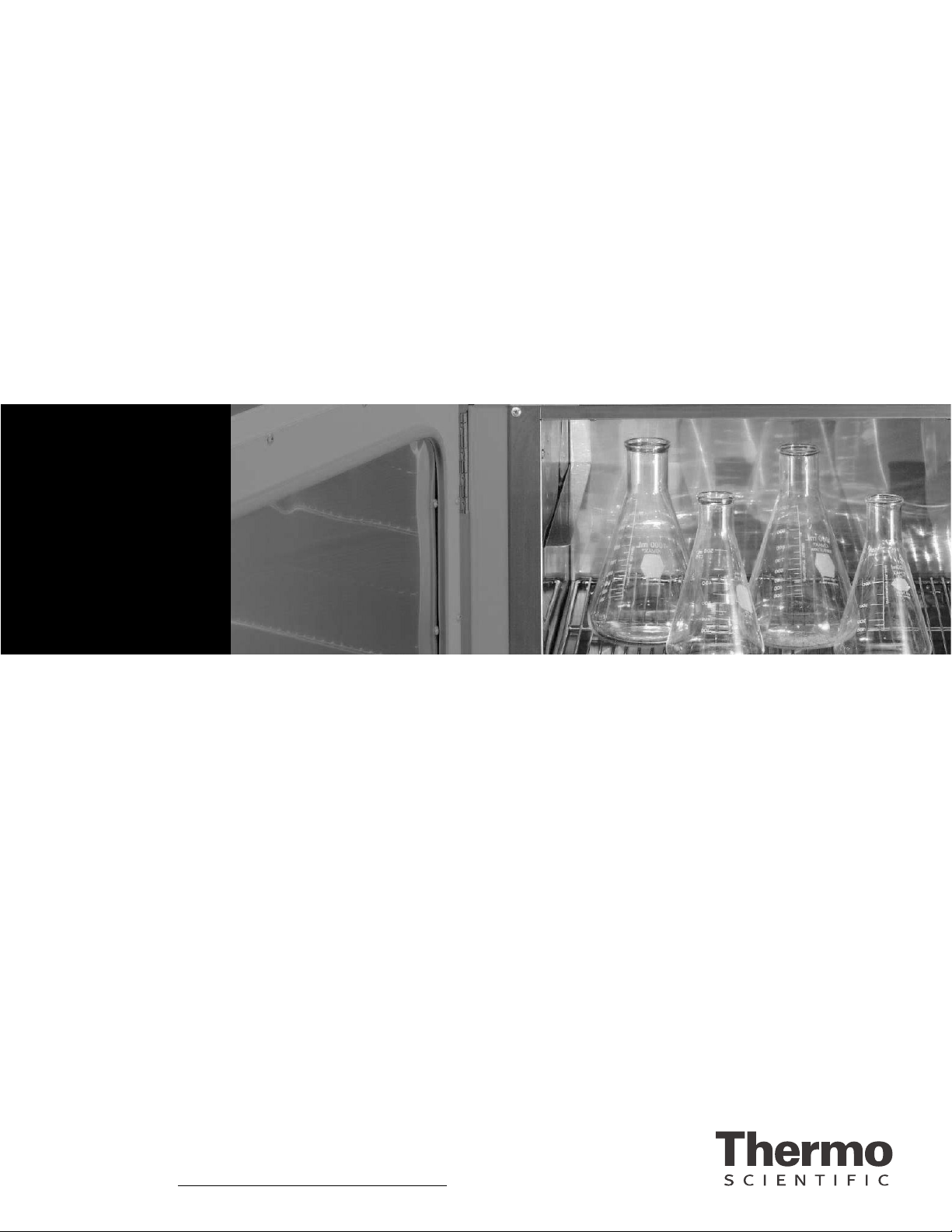
The Vacuum Oven design features a 1.5 cubic-foot stainless steel chamber
with fully adjustable shelves. An additional feature is a chamber door with
full view, and tempered safety glass.
The stainless steel chamber permits performance of practically every
laboratory need associated with general drying, curing, conditioning,
desiccating, annealing, and moisture tests. Additional applications include
vacuum embedding, out-gassing solids and liquids, aging tests, plating, and
electronic process control.
Five built-in, self diagnostic features – open thermocouple, over-
temperature, power failure, low battery, and calibration data corruption -
on the front panel display to alert the operator of a malfunction and thus
prevent damage to both samples and equipment.
Warning This unit is not explosion proof. Do not use in the presence of
flammable or combustible materials; fire or explosion may result. Unit
contains components that may ignite such materials. Do not place volatile
items in the chamber. Fumes and spillage from acidic solutions cause
corrosion of the stainless steel chamber and the door gasket. are should
be taken to maintain neutral pH at all times. s

1-2 Programmable Vacuum Oven Thermo Scientific
Section 1
Introduction
Performance haracteristics
Temperature Display Range . . .Ambient to 280° w/ 1° resolution
Temperature ontrol Range . . . . . . .50 to 280° w/ 1° resolution.
Heat Rise time . . . .Ambient to 100° in <30 minutes, w/ temp set
to 200°
Temperature Set-Point Accuracy . . . . .±2° from 50 to 280°
Temperature Set-Point Reproducibility . .±0.1°
Temperature Stability . . . . . . . . . . . . . . . .±0.3°
Temperature Display . . . . . .4 digit alphanumeric
Average Temperature Uniformity . . . ±5° at 25" Hg below
atmosphere, ≥5" Hg vacuum on the oven's display, based upon
measuring points at the geometric center and each corner of oven
chamber at 100° in compliance with DIN 12880 2007-05
Vacuum Specifications
Vacuum Pump Down Time . . To 1.0 in. Hg in 6 mins using
12 LPM vacuum pump
Average Leak Rate . . . . . .<1 in. Hg per 24 hours
Vacuum Display Range . . 0.0 in. Hg to one atmosphere (in. Hg)
Vacuum Display Accuracy . .Average error 0.2 in. Hg after calibration
Atmosphere ontrol . . Use with non-corrosive, non-flammable gases
such as nitrogen and O2
Power Requirements
atalog No. 3628A . . . .115V ±10%, 14.7 Amps, 50/60 Hz
atalog No. 3628A-1 . . 230V ±10%, 7.4 Amps, 50/60 Hz
Power onsumption . . . . . . . . . . . . . .1700 watts
Vacuum Pump ontacts (Tabs 3 and 4) . . .15A@ 240VA , Max
Environmental
Operating Temperature . . . . . . . . . .60° to 100°F
Storage Temperature . . . . . . . . . . . .32° to 120°F
Recorder Outputs
Temperature, Pins P3-1, P3-2 . . . . . . .10 mv/°
hamber Pressure, Pins P3-3, P3-4 . . . 100 mv/in. Hg
onnector Type: AMP 640456-4
Physical haracteristics
External Dimensions . . . . .26”W x 23”D x 22”H
hamber Size . . . . . . . . . .12”W x 18”D x 12”H
hamber Volume . . . . . . . . . . . . . . . . .1.5 cu. ft.
Specifications

Programmable Vacuum Oven 2-1Thermo Scientific
Section 2 Unpacking
Refer to the packing list below and be certain that all listed items are
present. Inspect to ensure that the unit has not been damaged during
shipment. If the unit appears to have sustained shipping damage, contact
the distributor from whom you purchased this product or Technical
Services.
uantity Description
1 Vacuum Oven
2 Shelves (shipped in chamber)
2 Hose Connectors
1 Operating Manual
If any of these items are missing from the carton, contact Technical
Services.
Before operating the vacuum oven, the user should ensure that all packing
material has been removed from the interior of the chamber.


Programmable Vacuum Oven 3-1Thermo Scientific
Section 3 Controls, Indicators and
Connectors
Before putting the Vacuum Oven into operation, the user should become
thoroughly familiar with the location and function of all controls,
indicators, and connectors. Most are clearly labeled and located on or
below the front panel, with the exception of the two (PURGE and
VA UUM) hose connectors, which are located on the lower, right side of
the oven. A set of vacuum pump auxiliary contacts and the temperature/
vacuum recorder output connectors are located on the rear side of the
control board. See following pages in this section for instructions on
accessing these connectors. The control panel consists of two 14-segment
alphanumeric displays, six indicator LEDs, four keypads, and an ON/OFF
toggle. The VA UUM and PURGE valves are located just beneath the
control panel.
A four character alphanumeric readout that alternately displays the day of
the week and time of day in 5-second intervals.
A four character alphanumeric readout that alternately displays the
temperature (° ) and chamber pressure (in. Hg) in 5-second intervals.
AM: Indicates first 12 hrs. of a day is being displayed/programmed
in the upper display window. Flashes when in alibration
mode.
° : Indicates chamber temperature (° ) is being
displayed/programmed in the lower display window.
in. of Hg: Indicates chamber pressure is being displayed in the lower
display window. Also illuminated during vacuum pump
program step.
Heater: Indicates heater activation.
Pump: Indicates closed vacuum pump contact condition.
Program: Indicates 7-day program setup or operation.
Day/Time Display
Temp/Vacuum
Display
LED Indicators

3-2 Programmable Vacuum Oven Thermo Scientific
Section 3
Controls, Indicators and Connectors
Keypad
Menu: Allows operator to cycle through main menu and calibration menu.
Set: Selects one of six main menu parameters and one of five calibration
menu parameters.
Increase: Increments values to be selected for each parameter.
Decrease: Decrements values to be selected for each parameter.
Power Switch: A rocker type switch that controls power to Vacuum Oven.
Vacuum ontrol Valve: A forged body, shut-off valve used to open and
close the connection to an auxiliary vacuum pump. Valve port accepts a
supplied serrated fitting to ease in connecting a 1/4-inch (inside diameter)
hose.
Purge ontrol Valve: A forged body, shut-off valve used to open and close
the connection to an auxiliary gas source. Valve port accepts a supplied
serrated fitting for ease in connecting a 1/4-inch (inside diameter) hose.
Vacuum Inlet Port: A serrated hose fitting used to connect an auxiliary
vacuum pump to the oven. Fitting accepts a 1/4-inch (inside diameter)
hose.
Temperature/
Vacuum Display
Day/Time Display
Power Switch
PurgeControlValve
Vacuum Control
Valve
Figure 3-1. Control Panel
Connectors and
Valves

Programmable Vacuum Oven 3-3Thermo Scientific
Section 3
Controls, Indicators and Connectors
Purge Inlet Port: A serrated hose fitting used to connect an auxiliary gas
source to the vacuum oven. Fitting accepts a 1/4-inch (inside diameter)
hose.
Vacuum Port Auxiliary ontacts: Normally open contacts located at the
bottom of the rear side of the control board (Tabs 3 and 4). The contacts
close when either the pump is manually activated at the keypad, or by
running a program step that calls for pump activation.
Temperature and Vacuum Recorder Outputs: Four pins located on the
top, right of the rear side of the control board (P3) which provide a
voltage readout corresponding to chamber temperature and/or pressure.
alibration Jumper Pin (JP4): Group of four pins located in the center of
the rear of the control board. The lower two pins when jumped enable
calibration mode. See Figure 2 for controller rear view.
Warning Secured access panels, covers, etc., should only be removed from
this equipment by trained service personnel. Hazardous voltages are
present at various internally exposed points. s
Connectors and
Valves (continued)
Battery Module
Calibrationjumper (JP4)
shownincalibration
mode.
Control Thermocouple
Input
Display Thermocouple
Input
Figure 3-2. Control Board

A group of five messages alert the operator to heater and control
malfunctions. The OT (open thermocouple) and OVR (over
temperature) errors alternately display in the TEMP/VA UUM display.
The PWRF (power failure), BATT LOW (low battery) and R
(calibration data corruption) are displayed in the DAY/TIME display
window. All messages and their meanings are as follows:
OT (Open Thermocouple)
The TEMP/VA UUM display alternates between OT and current
chamber pressure at 5 second intervals, where OT replaces the normal
process temperature display field. The heaters and vacuum pump (if con-
nected to auxiliary contacts) are forced OFF. Program execution stops.
OVR (Over Temperature)
Activates if oven temperature exceeds the set point +25° .
PWRF (Power Failure)
Power failure only detected during program mode. The failure must be
longer than 2 minutes. Time display alternates between PWRF,
HH:MM and DAY(n) at 5 second intervals.
BATT LOW (Low Battery)
Indicates it is time to replace the 6-year battery module. Module is in
a socket on the back of the control board. See Fig. 2.
R ( alibration Data orrupted)
Indicates an error in the stored calibration data. The heater and pump
relay are forced off. Unit must be calibrated to clear.
Run Away Heater Safety
In the event that the heater triac or control malfunctions and results in a
run away heater, a secondary thermostat is in place that will automatical-
ly pick up control of the heaters at approximately 325° . If the set point
is above 270° and the display is indicating a chamber temperature of
325° (±12° ), this will be an indication that the secondary thermostat
has taken over control of the oven. If the set point is at 270° or below,
the temperature display will show OVR at every other temperature
display update. In either case, Technical Services should be contacted to
check the heater circuit.
3-4 Programmable Vacuum Oven Thermo Scientific
Section 3
Controls, Indicators and Connectors
Self-Diagnostic
Safety Monitors

Programmable Vacuum Oven 4-1Thermo Scientific
Section 4 Installation and Assembly
The Vacuum Oven is shipped assembled and ready for operation.
However, before installing the oven, the operating site should be prepared
to meet necessary requirements by following the guidelines below.
The standard plug configurations
are shown in Figure 4-1. The
115VA model is supplied with a
20 amp plug (NEMA 5-20P). The
230VA model is supplied with a
15-amp plug (NEMA 6-15P).
Verify that the appropriate
receptacle is at the location the
oven will be used.
Warning To avoid the risk of electrical shock, verify that the source plug is
properly grounded. s
The supporting bench or table must be capable of holding in excess of 200
pounds. The bench should be sufficient to accommodate sample-handling
processes. The oven itself is 26-inches wide and 23 inches deep; therefore,
the bench surface should be approximately 48 inches wide and 30 inches
deep to allow for ventilation clearance at the rear of the oven.
Warning To avoid the risk of fire, provide 6 inches of clearance for the
top, back and sides of the oven. Do not set or lean any objects against or
on top of the oven while hot. s
For installations that may use a tank atmosphere, check that site facilities
and tank equipment are in compliance with OSHA requirements for
handling compressed gas. Responsible personnel must also be thoroughly
knowledgeable in the use, storage, and handling of compressed gases.
When using a tank atmosphere, a 1/4”tube to 1/4”pipe adapter is
required for the regulator outlet of the tank. This adapter is not supplied.
A Swagelok B-400-7-4 adapter, or equivalent, may be used. Also, 9/16”,
and 1-1/8”open-end or, preferably, flare-nut wrenches are required.
Site Requirements
5-20P 6-15P
Figure 4-1. Standard Plug
Configurations

4-2 Programmable Vacuum Oven Thermo Scientific
Section 4
Installation and Assembly
Site Requirements
(continued)
After verifying all site and safety requirements, the following steps should
be completed to prepare the vacuum oven for operation:
1. Verify that all packing items and securing materials have been removed
from the oven.
2. Move the oven to the desired location as specified.
3. Locate the two serrated hose fittings, packed in the INSTRU TIONS
envelope accompanying each oven.
4. Install the hose fittings on the VA UUM and PURGE ports located
on the lower right side panel. Hose fittings should be installed by
turning the fitting nut clockwise until finger-tight then, using a 9/16”
wrench, turn the nut an additional 1/4-turn while holding the fitting
stationary with a 3/8”wrench.
5. lose both the PURGE and VA UUM valves by turning the control
knob clockwise as far as possible.
6. onnect a vacuum pumping system, including a suitable trap, to the
serrated fitting labeled VA UUM. Use 1/4”I.D. heavy-walled vacuum
tubing and secure the connection with a hose clamp.
7. If desired, connect a purge gas supply to the serrated fitting labeled
PURGE, using a suitable length of 1/4”I.D. tubing. Use a two-stage
gas flow regulator if gas is to be supplied by a pressurized cylinder.
8. After installing connecting tubing, check that the PURGE
ONTROL valve on the unit is closed (full clockwise position), then
open the regulator flow control valve to pressurize the line. At this
point, check all connections for leaks, using an ordinary soapy water
solution.
9. heck data plate and plug line cord into a suitable power receptacle.

Programmable Vacuum Oven 5-1Thermo Scientific
Section 5 Operation
Energize the oven by switching the ON/OFF toggle to the ON position.
The upper display will show VER while the lower display will show 1.x,
where x is the current software version. Next, the DAY/TIME display will
begin alternating between the day of week and the time of day. At the
same time, the TEMP/VA UUM display will alternate between chamber
temperature (° ) and chamber pressure (in. Hg). This is the default
display. Press the MENU key to scroll through menus 1-6, then press SET
to enter a menu. When there is no keypad activity for 5 seconds, the unit
returns to Menu 1 automatically. The following table lists the main menus
and their functions. The tables that follow list the subcategories of the
main menu and describe the function of each.
Table 5-1. Main Controller Menu
Menu Prompt Display Functions Setup Functions
1 (Default)
Top Display – Day of week, Time of day
Bottom Display – Temperature (°C),
Pressure (in. Hg)
Adjust temperature control
setpoint. Turn vacuum pump
contacts ON/OFF
2 AD T Display temperature offset value Adjust temperature control
offset
3 AD P Displays pressure offset value Adjust for barometric pressure
variations
4 TSET Displays flashing day or time of day Set clock and day of the week
5 PRGM Displays program mode Start/Stop program mode
6 PSET Displays day, step and set-point Program 7 – Day event timer

5-2 Programmable Vacuum Oven Thermo Scientific
Section 5
Operation
Table 5-2. Default Menu (Menu 1)
Table 5-3. Adjust Temperature Offset (Menu 2 - AD T)
Table 5-4. Adjust Barometric Pressure (Menu 3 - AD P)
Step Key Entry Action Display
1 Press SET
Enter Temperature Set-point mode with the cur-
rent set point displayed. Use the UP/DOWN keys
to adjust the set point. (Range 16 to 280°C).
SP: 280
2 Press SET 2nd Time
The temperature set point is updated and the
vacuum pump ON/OFF option is displayed. Use
the UP key to change the bottom display to YES
and switch the pump on. Use the DOWN arrow
key to change the display back to NO and turn the
pump contacts OFF.
PUMP OFF
3 Press SET or wait 2
seconds
The pump contacts are set as desired above. Unit
returns to the default menu after 2 seconds of
inactivity.
Default
Step Key Entry Action Display
1
Press MENU until AD T is displayed, then press SET.
Use the UP/DOWN keys to adjust the temperature off-
set. (Range ±30°C). AD T value is added to temperature
display.
AD T 02 AD T
02
2 Press SET or wait 2 seconds Unit returns to the
default menu. Default
Step Key Entry Action Display
1Press MENU until AD P is dis-
played, then press SET.
Use the UP/ DOWN keys to adjust the
pressure offset. (Range ±8.0 inHg) AD P
value is added to pressure display.
AD P
0.0
2 Press SET or wait 2 seconds Unit returns to the default menu. Default

Table 5-5. Set Time and Day (Menu 4 - TSET)
Table 5-6. Program Mode ON/OFF (Menu 5 - PRGM)
Programmable Vacuum Oven 5-3Thermo Scientific
Section 5
Operation
Step Key Entry Action Display
1 Press MENU until TSET is dis-
played, then press SET
Unit enters set time and day mode and
the current hour and minute is displayed.
Hours digits are flashing. Use the
UP/DOWN keys to adjust the hour (12
HR clock).
08:00
AM •
2 Press SET
Hours are entered and minutes are
flashing. Use the UP/ DOWN keys to
adjust minutes.
08:00
AM •
3 Press SET
Day of the week is displayed (flashing).
Use the UP/DOWN keys to adjust the
day of the week.
MON
4 Wait 2 seconds Unit returns to default menu. Default
Step Key Entry Action Display
1 Press MENU until
PRGM is displayed.
Use the Up arrow key to change the bottom
display to ON, or the down arrow key to change
the display to OFF.
PGRM
ON
2 Press SET or wait 2
seconds
If the program menu was set ON, the program will
execute. If it was set to OFF, the control returns to
default mode.
Default
This manual suits for next models
1
Table of contents
Other Thermo Scientific Oven manuals

Thermo Scientific
Thermo Scientific OGS 60 User manual

Thermo Scientific
Thermo Scientific 3051 Series User manual

Thermo Scientific
Thermo Scientific 3490M User manual

Thermo Scientific
Thermo Scientific Lindberg Blue M 3055 Series User manual

Thermo Scientific
Thermo Scientific NAPCO 6508 User manual

Thermo Scientific
Thermo Scientific PRECISION 6502 Manual

Thermo Scientific
Thermo Scientific 625S User manual

Thermo Scientific
Thermo Scientific PR305225G User manual

Thermo Scientific
Thermo Scientific Lindberg/Blue M VO Series User manual

Thermo Scientific
Thermo Scientific NAPCO 6506 User manual