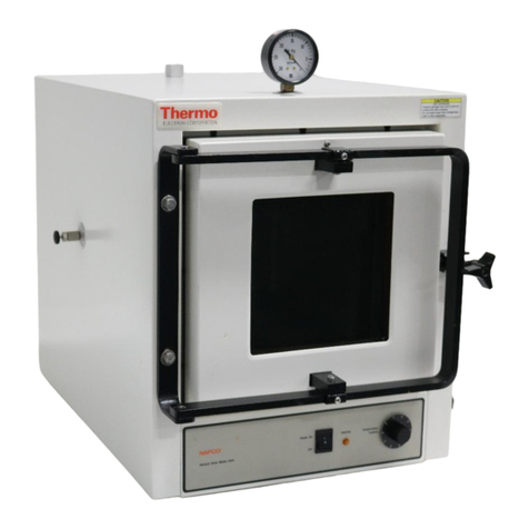
Thermo Scientific 3490M User manual

Class “100” Clean Room Ovens
Operating Manual and Parts List LT1476X7 Rev. 0
Visit us online to register your warranty
www.thermoscientific.com/MBCwarranty

Thermo Scientific
MANUAL NUMBER LT1476X7 (7006879)
-- -- 8/29/14 Corrected typo on pg 4-1 3480-2 to 3485-2 ccs
0 -- 6/4/10 Transfer to Marietta (was LT1476X7 5/30/08) ccs
REV ECR/ECN DATE DESCRIPTION By
Preface
Clean Room Oven i
Models covered in this manual
Models Size Voltage With HEPA Filter
3490M (6879) 2.6 cu ft 120V
3490M-1 (6880) 2.6 cu ft 240V
3492M (6881) 2.6 cu ft 120V
3492M-1 (6882) 2.6 cu ft 240V
3494M-1 (6883) 2.6 cu ft 240V
3495M-1 (6884) 3.6 cu ft 240V
3496M-1 (6885) 2.8 cu ft 240V X
3497M-1 (6886) 2.8 cu ft 240V X
3498M-1 (6887) 4.6 cu ft 240V
3499M-1 (6888) 4.6 cu ft 240V

Thermo Scientificii Clean Room Oven
Preface
Important Read this instruction manual. Failure to read, understand and follow the instructions in this manual
may result in damage to the unit, injury to operating personnel, and poor equipment performance. ▲
Caution All internal adjustments and maintenance must be performed by qualified service personnel. ▲
Material in this manual is for information purposes only. The contents and the product it describes are subject to
change without notice. Thermo Fisher Scientific makes no representations or warranties with respect to this
manual. In no event shall Thermo be held liable for any damages, direct or incidental, arising out of or related to
the use of this manual.
©2010 Thermo Scientific. All rights reserved.

Thermo Scientific Clean Room Oven iii
Preface
Important operating and/or maintenance instructions. Read the accompanying text carefully.
Potential electrical hazards. Only qualified persons should perform procedures associated with this
symbol.
Equipment being maintained or serviced must be turned off and locked off to prevent possible injury.
Hot surface(s) present which may cause burns to unprotected skin, or to materials which may be
damaged by elevated temperatures.
Marking of electrical and electronic equipment, which applies to electrical and electronic equipment
falling under the Directive 2002/96/EC (WEEE) and the equipment that has been put on the market
after 13 August 2005.
This product is required to comply with the European Union’s Waste Electrical & Electronic
Equipment (WEEE) Directive 2002/96/EC. It is marked with the WEEE symbol. Thermo Fisher
Scientific has contracted with one or more recycling/disposal companies in each EU Member State
European Country, and this product should be disposed of or recycled through them. Further
information on Thermo’s compliance with this directive, the recyclers in your country and
information on Thermo products will be available at www.thermofisher.com.
✔Always use the proper protective equipment (clothing, gloves, goggles, etc.)
✔Always dissipate extreme cold or heat and wear protective clothing.
✔Always follow good hygiene practices.
✔Each individual is responsible for his or her own safety.

Thermo Scientificiv Clean Room Oven
Preface
Do You Need Information or Assistance on
Thermo Scientific Products?
If you do, please contact us 8:00 a.m. to 6:00 p.m. (Eastern Time) at:
1-740-373-4763 Direct
1-800-438-4851 Toll Free, U.S. and Canada
1-877-213-8051 FAX
http://www.thermoscientific.com Internet Worldwide Web Home Page
Service E-Mail Address
Thermo Fisher Scientific
401 Millcreek Road, Box 649
Marietta, OH 45750
Our staff can provide information on pricing and give you quotations. We can
take your order and provide delivery information on major equipment items or make
arrangements to have your local sales representative contact you. Our products are listed on the
Internet and we can be contacted through our Internet home page.
Our staff can supply technical information about proper setup, operation or
troubleshooting of your equipment. We can fill your needs for spare or replacement parts or
provide you with on-site service. We can also provide you with a quotation on our Extended
Warranty for your Thermo Scientific products.
Whatever Thermo Scientific products you need or use, we will be happy to discuss your
applications. If you are experiencing technical problems, working together, we will help you
locate the problem and, chances are, correct it yourself...over the telephone without a service
call.
When more extensive service is necessary, we will assist you with direct factory trained
technicians or a qualified service organization for on-the-spot repair. If your service need is
covered by the warranty, we will arrange for the unit to be repaired at our expense and to your
satisfaction.
Regardless of your needs, our professional telephone technicians are available to assist you
Monday through Friday from 8:00 a.m. to 6:00 p.m. Eastern Time. Please contact us by
telephone or fax. If you wish to write, our mailing address is:
International customers, please contact your local Thermo Scientific distributor.
Sales Support
Service Support
service.led.marietta@thermofisher.com

Clean Room Oven vThermo Scientific
Table of Contents
Description . . . . . . . . . . . . . . . . . . . . . . . . . . . . . . . . . . . . . . . . . . . . . . . . . .1-1
Safety Information . . . . . . . . . . . . . . . . . . . . . . . . . . . . . . . . . . . . . . . . . . . .2-1
Specifications . . . . . . . . . . . . . . . . . . . . . . . . . . . . . . . . . . . . . . . . . . . . . . .3-1
Unpacking and Installation . . . . . . . . . . . . . . . . . . . . . . . . . . . . . . . . . . . .4-1
Location . . . . . . . . . . . . . . . . . . . . . . . . . . . . . . . . . . . . . . . . . . . . . . .4-1
Stacking Units . . . . . . . . . . . . . . . . . . . . . . . . . . . . . . . . . . . . . . . . . .4-1
Electrical Power . . . . . . . . . . . . . . . . . . . . . . . . . . . . . . . . . . . . . . . . .4-2
Baking-Out the Oven . . . . . . . . . . . . . . . . . . . . . . . . . . . . . . . . . . . .4-2
Cleaning . . . . . . . . . . . . . . . . . . . . . . . . . . . . . . . . . . . . . . . . . . . . . . .4-2
Shelf Installation . . . . . . . . . . . . . . . . . . . . . . . . . . . . . . . . . . . . . . . .4-2
Leveling . . . . . . . . . . . . . . . . . . . . . . . . . . . . . . . . . . . . . . . . . . . . . . .4-2
Door Adjustment . . . . . . . . . . . . . . . . . . . . . . . . . . . . . . . . . . . . . . . .4-3
Gas Connection . . . . . . . . . . . . . . . . . . . . . . . . . . . . . . . . . . . . . . . . .4-3
Latch Adjustment -Door Hard to Open . . . . . . . . . . . . . . . . . . . . . .4-4
Latch Adjustment -Door Against Gasket . . . . . . . . . . . . . . . . . . . . . .4-4
Latch Adjustment -Heating Door Opens . . . . . . . . . . . . . . . . . . . . .4-5
Features . . . . . . . . . . . . . . . . . . . . . . . . . . . . . . . . . . . . . . . . . . . . . . . . . . . . .5-1
Control Panel . . . . . . . . . . . . . . . . . . . . . . . . . . . . . . . . . . . . . . . . . . .5-1
Section 1
Section 2
Section 3
Section 4
Section 5

vi Clean Room Oven Thermo Scientific
8 Segment & 4x16 Segment Programmable Models . . . . . . . . . . . . . .6-1
To View the Display Units . . . . . . . . . . . . . . . . . . . . . . . . . . . . . . . . .6-2
To Change the Setpoint . . . . . . . . . . . . . . . . . . . . . . . . . . . . . . . . . . .6-2
Basic Operation . . . . . . . . . . . . . . . . . . . . . . . . . . . . . . . . . . . . . . . . .6-2
To View the % Output Power . . . . . . . . . . . . . . . . . . . . . . . . . . . . . .6-3
Buttons and Indicators . . . . . . . . . . . . . . . . . . . . . . . . . . . . . . . . . . . .6-3
Controller Parameters . . . . . . . . . . . . . . . . . . . . . . . . . . . . . . . . . . . . .6-4
Alarms . . . . . . . . . . . . . . . . . . . . . . . . . . . . . . . . . . . . . . . . . . . . . . . .6-6
Single Setpoint Controller Operation . . . . . . . . . . . . . . . . . . . . . . . . .6-7
Sensor Break Protection . . . . . . . . . . . . . . . . . . . . . . . . . . . . . . . . . . .6-7
Programming the Controller . . . . . . . . . . . . . . . . . . . . . . . . . . . . . . .6-7
Creating a New or Editing an Existing Program . . . . . . . . . . . . . . .6-7
Hb: Holdback . . . . . . . . . . . . . . . . . . . . . . . . . . . . . . . . . . . . . . . . .6-8
CYC.n: Setting the Number of Cycles . . . . . . . . . . . . . . . . . . . . . .6-9
dwL.U: Setting Dwell Units . . . . . . . . . . . . . . . . . . . . . . . . . . . . . .6-9
rmP.U: Setting Ramp Units . . . . . . . . . . . . . . . . . . . . . . . . . . . . . . .6-9
Setting the Segment Type . . . . . . . . . . . . . . . . . . . . . . . . . . . . . . .6-10
Setting the Target Setpoint . . . . . . . . . . . . . . . . . . . . . . . . . . . . . .6-13
Cancelling a Program . . . . . . . . . . . . . . . . . . . . . . . . . . . . . . . . . . . .6-13
Holding a Program . . . . . . . . . . . . . . . . . . . . . . . . . . . . . . . . . . . . . .6-13
Running a Program . . . . . . . . . . . . . . . . . . . . . . . . . . . . . . . . . . . . .6-13
Tuning Your Oven . . . . . . . . . . . . . . . . . . . . . . . . . . . . . . . . . . . . . .6-14
Tuning Error . . . . . . . . . . . . . . . . . . . . . . . . . . . . . . . . . . . . . . . . .6-14
Gain Scheduling . . . . . . . . . . . . . . . . . . . . . . . . . . . . . . . . . . . . . . . .6-14
Autotuning . . . . . . . . . . . . . . . . . . . . . . . . . . . . . . . . . . . . . . . . . .6-15
Adaptive Tuning . . . . . . . . . . . . . . . . . . . . . . . . . . . . . . . . . . . . . .6-16
Maintenance . . . . . . . . . . . . . . . . . . . . . . . . . . . . . . . . . . . . . . . . . . . . . . . .7-1
Door Gasket Repair . . . . . . . . . . . . . . . . . . . . . . . . . . . . . . . . . . . . . .7-1
Complete Gasket Replacement . . . . . . . . . . . . . . . . . . . . . . . . . . . . .7-2
Filter Replacement . . . . . . . . . . . . . . . . . . . . . . . . . . . . . . . . . . . . . . .7-2
Parts Replacement/General . . . . . . . . . . . . . . . . . . . . . . . . . . . . . . . .7-2
Replacement Parts . . . . . . . . . . . . . . . . . . . . . . . . . . . . . . . . . . . . . . . . . . .8-1
Ordering Procedures . . . . . . . . . . . . . . . . . . . . . . . . . . . . . . . . . . . . .8-2
Table of Contents
Section 6
Section 8
Section 7

Clean Room Oven 1-1Thermo Scientific
Section 1 Description
This advanced series of Ultra-Clean 100 ovens incorporates programmer-
controller which can be conveniently and easily operated by the user from
a front panel keyboard. Mnemonics in the display area of the programmer-
controller keeps the user informed of the parameters which are being acted
upon. An additional option allows the unit to be operated in either
automatic or manual mode.
Mechanical air circulation provides optimum temperature uniformity and
rapid recovery after door openings.
Two systems protect oven contents against overheating. An alarm setpoint
programmed in the controller initiates a visual signal in the event the
actual temperature exceeds the limit. In addition, a second system is an
independent hydraulic thermostat set by the operator to a temperature
slightly higher than the maximum operating temperature. This thermostat
is a mechanical backup to protect contents in the unlikely event the
programmer-controller experiences a failure. A red status lamp warns of
the overtemperature condition.


Clean Room Oven 2-1Thermo Scientific
Section 2 Safety Information
Your Thermo Scientific Class “100” Clean Room Oven has been designed
with function, reliability, and safety in mind. It is your responsibility to
install it in conformance with local electrical codes. It is most important
that the user follow installation instructions exactly as written. Failure to
do so is likely to lead to improper operation, erroneous calibrations and
possible damage to the equipment. Do not attempt operation without this
information.


Clean Room Oven 3-1Thermo Scientific
Section 3 Specifications
Power Requirements
All models accept 50 Hz or 60 Hz current.
Temperature Range
Slightly above ambient to +250°C.
Temperature Control
Model . . . . . . . . . . . . . . . . . . . . . . . . . . . . .@100°C @200°C
3490M, -1, 3492M-1 . . . . . . . . . . . . . . . . . . .±0.1°C ±0.2°C
3494M-1, 3495M-1 . . . . . . . . . . . . . . . . . . . .±0.1°C ±0.2°C
3496M-1, 3497M-1 . . . . . . . . . . . . .±0.2°C (@90°C)
3498M-1, 3499M-1 . . . . . . . . . . . . . . . . . . . .±0.1°C ±0.2°C
Temperature Uniformity
Model . . . . . . . . . . . . . . . . . . . . . . . . . . . . .@100°C @200°C
3490M, -1, 3492M-1 . . . . . . . . . . . . . . . . . .±1.0°C ±2.0°C
3494M-1, 3495M-1 . . . . . . . . . . . . . . . . . . .±1.0°C ±2.0°C
3496M-1, 3497M-1 . . . . . . . . . . . .±1.5°C (@90°C)
3498M-1, 3499M-1 . . . . . . . . . . . . . . . . . . .±1.0°C ±2.0°C
Model Volts AC Watts Amps Heaters
3490M, 3492M 120 1900 15.8 2
3490M-1, 3492M-1 220/240 1900 7.9 2
3494M-1, 3495M-1 220/240 3100 12.9 2
3496M-1, 3497M-1 220/240 3100 12.9 2
3498M-1, 3499M-1 220/240 3100 12.9 2

3-2 Clean Room Oven Thermo Scientific
Section 3
Specifications
Temperature Rise Times
3490M, -1, 3492M-1 . . . . . . . . . . . . . .22.0 minutes
3494M-1, 3495M-1 . . . . . . . . . . . . . . .18.0 minutes
3496M-1, 3497M-1 .1.0 minutes (ambient to 90°C)
3498M-1, 3499M-1 . . . . . . . . . . . . . . .20.5 minutes
Temperature Recovery Time of Load
3490M, -1, 3492M-1 . . . . . . . . . . . . . . . . .8 minutes
3494M-1, 3495M-1 . . . . . . . . . . . . . . . . . .4 minutes
3496M-1, 3497M-1 . . . . . . . . . . . . . . . . .11 minutes
(@90°C: after 1 min., door opening of 90 degrees)
3498M-1, 3499M-1 . . . . . . . . . . . . . . . . . .7 minutes
Method
Door open 90° for 1 minute. Oven loaded with 9, 4" wafer boats filled
with wafers and evenly distributed in the oven. A thermocouple measured
wafer temperature in the center wafer boat. Time recorded equals elapsed
time for wafer temperature to reach 90% of setpoint (150°C).
Note Performance measured under controlled laboratory conditions. Your
oven's performance may be slightly different, depending on application. ▲
Dimensions
3490M, -1, 3492M-1
Interior: 13"W x 18"D x 19-1/2"H (33 x 46 x 50 cm)
Exterior : 21-5/8"W x 24-1/4"D x 35"H (55 x 62 x 89 cm)
Capacity: 2.6 cubic feet
3494M-1, 3495M-1
Interior: 18"W x 18"D x 19-1/2"H (46 x 46 x 50 cm)
Exterior: 26-5/8"W x 24-1/4"D x 35"H (68 x 62 x 89 cm)
Capacity: 3.6 cubic feet

Clean Room Oven 3-3Thermo Scientific
Section 3
Specifications
Dimensions (continued)
3496M-1, 3497M-1
Interior: 14"W x 18"D x 19-1/2"H (36 x 46 x 50 cm)
Exterior: 26-5/8"W x 24-1/4"D x 35"H (68 x 62 x 89 cm)
Capacity: 2.8 cubic feet
3498M-1, 3499M-1
Interior: 23"W x 18"D x 19-1/2"H (58 x 46 x 50 cm)
Exterior: 31-5/8"W x 24-1/4"D x 35"H (80 x 62 x 89 cm)
Capacity: 4.6 cubic feet
Weight (net)
3490M, -1, 3492M-1: 180 lbs. ( 81.8 kg)
3494M-1, 3495M-1: 220 lbs. (100.0 kg)
3496M-1, 3497M-1: 202 lbs. ( 91.8 kg)
3498M-1, 3499M-1: 234 lbs. (106.4 kg)
Environmental Conditions
Pollution Degree: 2
Installation Category: II
Altitude: 2000 meters MSL (mean sea level)
Humidity: 80% maximum, non-condensing
Electrical supply: 120VAC or 240VAC
Voltage tolerance: ±10% of normal rated line
Temperature: 15°C to 40°C
Product usage: This product is intended for use indoors only.


Clean Room Oven 4-1Thermo Scientific
Section 4 Unpacking and Installation
The shipping carton should be inspected upon delivery. When received,
carefully examine for any shipping damage before unpacking. If damage is
discovered, the delivering carrier should both specify and sign for the
damage on your copy of the delivery receipt.
Open the carton carefully making certain that all parts are accounted for
before packaging materials are discarded. After unpacking, if damage is
found, promptly report it to the carrier and request a damage inspection
promptly.
Important Failure to request an inspection of damage within a few days
after receipt of shipment absolves the carrier from any liability for damage.
Call for a damage inspection promptly.
BE ADVISED: Ovens must be cleaned and baked-out prior to use in clean
rooms.
Note Disconnect unit from the power source when not in use. ▲
Place the oven where it is to be operated, in an area away from drafts.
Provide enough clearance to allow free air movement around the oven.
Leave clearance at the rear for gas connection and adjustment of air vent.
Position the unit with room for 90° of door opening to the right. The
oven must not be placed on a combustible surface.
Warning These ovens should not be placed one on top of the other
because:
1) There is danger of the oven on top being accidentally knocked over
with possibility of serious injury and property damage;
2) Heat from oven below can damage control panel components of
oven above with possible resulting electrical short and fire.
To arrange ovens vertically, order optional space saver stacking rack
(Model 3485-2). ▲
Location
Stacking Units

4-2 Clean Room Oven Thermo Scientific
Section 4
Unpacking and Installation
Leveling The oven should be level, though its operation does not depend on this.
Do not remove the oven’s rubber feet - they are necessary for proper
ventilation; removing the rubber feet may also cause erratic temperature
control and damage to the electronic components.
Install shelf guides in desired locations along the inside sides of the oven.
Make sure the pair of guides for each shelf are at the same level. Each guide
has 2 sets of tabs. Insert the top tabs first, then the bottom tabs. Slide
shelves into place.
The following procedure is based on test information and a survey of
methods currently used by microchip manufacturers.
• The person cleaning the oven prior to clean room use should wear
disposable polyethylene gloves to prevent skin oils from contaminating
the oven surfaces.
• Use a lint-free soft paper manufactured for clean room maintenance.
• Remove shelves, floor and inside side walls from oven and clean
thoroughly. Clean interior chamber, including heaters, blower wheel
and, very gently, the sensor tube.
• Move the oven into the clean room and follow installation procedures,
noting that it must be cleaned AGAIN before use.
After installing the shelves, bake the empty oven with a steady air exchange
until particle count is reduced to an acceptable level. For working
temperatures about 200°C, bake 2 to 3 hours at 200°C.
Turn the power switch (on the left side of the front panel) to OFF-the
bottom half of the rocker pushed in. Plug the oven into an electrical outlet
providing the power that is specified on the oven nameplate.
Shelf Installation
Cleaning
Baking-Out the Oven
Electrical Power

Clean Room Oven 4-3Thermo Scientific
Section 4
Unpacking and Installation
Inert gas, such as nitrogen, can be injected into the chamber to flush out
impurities. The gas inlet, on the back of the oven, is a 1/8-inch NPT pipe.
Connect Tygon® R-3603 tubing to this pipe and to the dual regulator on
the gas source. Leave the gas turned off until the oven is being operated.
If the oven is to be operated without gas, keep the inlet capped-DO NOT
USE THE PLASTIC SHIPPING CAP.
Warning Inject only an inert gas into the oven. The use of any other type
gas may lead to fire or explosion and serious injury or death and property
damage. ▲
During shipping, the oven door may have been knocked out of line. The
following procedure will correct door-to-body and door-to-gasket
misalignment.
1. Lay the unit on its back. If exhaust and purging ports are fitted,
support the unit on 2' x 4's to protect these components.
2. Remove the pivot bolt and flat washer from the top door hinge.
3. Unlatch the door handle to release the door, then slide the door out
and off the bottom hinge pivot bolt to gain access to hinge screws.
4. Slightly loosen hinge screws on top and bottom hinges, so hinges
require firm hand pressure to reposition. DO NOT REMOVE
HINGE SCREWS - complete removal of screws will make it extremely
difficult to reassemble the hinge.
5. Replace the door on the bottom hinge pin and fit the door in place.
Loosen the bottom hinge pivot bolt with an open-end wrench. Replace
the top hinge pivot bolt and set it to be finger-tight.
6. Align the door to the body-top, bottom and sides.
7. Remove the top hinge pivot-bolt again, noting the position of properly
aligned hinges. Remove the door carefully without moving the hinges
out of position.
8. Tighten all hinge screws VERY securely.
9. Replace door on bottom hinge pivot bolt. Replace the top pivot bolt
and washer. Tighten top and bottom hinge pivot bolts VERY securely
to maintain proper alignment.
Gas Connection
Door Adjustment

If the door does not fit snug against the gasket, follow the procedure below
to adjust latch.
1. Open the door. Use a 5/64" Allen wrench to remove the Allen setscrew
from the door strike assembly.
2. Rotate the catch mechanism clockwise to shorten length and thereby
bring door closer to body of oven. The number of turns will have to be
estimated.
3. Re-insert and tighten the Allen setscrew securely.
4. Repeat this procedure as necessary to achieve a tight seal.
If the door is too hard to open, follow the procedure below to adjust the
latch.
1. Open the door. Use 5/64" Allen wrench to remove the Allen setscrew
from the door strike assembly.
2. Rotate catch mechanism counterclockwise to increase length and,
thereby, position door a little farther away from the body of the oven.
The number of turns will have to be estimated. Reinsert and tighten
Allen setscrew securely.
3. Repeat if necessary to achieve satisfactory operation.
4-4 Clean Room Oven Thermo Scientific
Section 4
Unpacking and Installation
Latch Adjustment -
Door Against Gasket
Latch Adjustment -
Door Hard to Open
Allen Setscrew
Figure 4-1. Door Strike Mechanism

If the door opens while oven is heating, follow the procedure below to
adjust the latch. The door will have to be adjusted to close more easily to
allow for the expansion occurring during heating.
1. Open the door. Use 5/64" Allen wrench to remove the Allen setscrew
from the door strike assembly.
2. Rotate catch mechanism counterclockwise to increase length and,
thereby, position door a little farther away from the body of the oven.
The number of turns will have to be estimated. Re-insert and tighten
Allen setscrew securely.
3. Repeat if necessary to achieve satisfactory operation.
Depending on operating temperature, the procedure may have to be
repeated to ensure proper door operation.
Clean Room Oven 4-5Thermo Scientific
Section 4
Unpacking and Installation
Latch Adjustment -
Heating Door Opens
This manual suits for next models
9
Table of contents
Other Thermo Scientific Oven manuals

Thermo Scientific
Thermo Scientific 6253 User manual

Thermo Scientific
Thermo Scientific Lindberg Blue M 3055 Series User manual

Thermo Scientific
Thermo Scientific PRECISION 6502 Manual

Thermo Scientific
Thermo Scientific 625S User manual

Thermo Scientific
Thermo Scientific PR305225G User manual

Thermo Scientific
Thermo Scientific Lindberg/Blue M VO Series User manual

Thermo Scientific
Thermo Scientific OGS 60 User manual

Thermo Scientific
Thermo Scientific 3051 Series User manual

Thermo Scientific
Thermo Scientific NAPCO 6506 User manual

Thermo Scientific
Thermo Scientific OGH 60 Series User manual