Thermo Solar SGC16H User manual

SGC16H
Differential controller
SGC16H: 1 output, 2 inputs
ENG
SVK
Differenzregler
SGC16H: 1 Ausgang, 2 Eingänge
Diferenčný regulátor
SGC16H: 1 výstup, 2 vstupy
DEU
A1360_1
MJ/OD
06/2018

A1360_1
MJ/OD
06/2018

ENGDEUSVK
Differential controllers
SGC16H
Differenzregler
SGC16H
Diferenčný regulátor
SGC16H
A1360_1
MJ/OD
06/2018

4
ENG
INTRODUCTION
Differential controllers SGC16H are modern designed, microprocessor-driven devices
made with digital and SMT technology.
These devices are intended for regulating domestic hot water warming by means of solar
collectors or for regulating domestic hot water warming by means solid fuel boiler, electric
heater or other energy resources.
Differential controllers SGC16H
For initial setup see Initial controller setup, page 7!
A1360_1
MJ/OD
06/2018

ENG
5
CONTENTS
USER MANUAL
Appearance of controller SGC16H ..........................................................................6
Initial controller setup.............................................................................................. 7
Graphic LCD display ............................................................................................. 9
Description of symbols shown on the display ....................................................... 10
Display for help, notices and warnings................................................................... 12
Menu entry and navigation .................................................................................. 13
Menu structure and description ............................................................................ 14
Temperature settings........................................................................................... 17
User functions .................................................................................................... 18
Operation mode selection .................................................................................... 19
Time program settings ........................................................................................ 20
Basic settings...................................................................................................... 23
Data overview ..................................................................................................... 25
SERVICE MANUAL
Controller parameters and auxiliary tools.............................................................. 26
Basic parameters............................................................................................. 26
Service parameters ......................................................................................... 28
Heat metering parameters ............................................................................... 32
Heat metering................................................................................................... 33
Factory settings .................................................................................................. 34
Controller data .................................................................................................... 34
INSTALLATION MANUAL
Controller installation .......................................................................................... 35
Wall installation ................................................................................................... 35
Marking and description of temperature sensors .................................................. 36
Controller’s electric connection.............................................................................. 37
Flow meter installation ........................................................................................ 38
Connection of a high-efficiency pump with an external control signal ...................... 38
Setting the flow in a solar system and testing the control function........................... 39
Temperature simulation mode............................................................................... 39
Technical data...................................................................................................... 40
Disposal of old electrical and electronic equipment ................................................ 41
Guarantee............................................................................................................ 42
Hydraulic and electric schemes........................................................................... 121
Installation record ............................................................................................... 125
A1360_1
MJ/OD
06/2018
6
User and settings manual
ENG
USER MANUAL
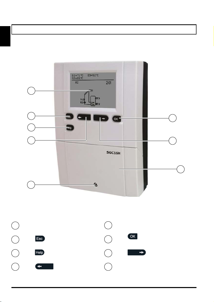
APPERANCE OF CONTROLLER SGC16H
Graphic display
Button
(Esc - return back)
Button (Help)
Button
(move to left, decreasing)
Screw for fastening the cover
Button
(menu entry, confirmation of selection)
2
1
3
5
4
6
7
8
Button
(move to right, increasing)
Cover for connection area
1
2
3
4
5
6
8
7
A1360_1
MJ/OD
06/2018
7User and settings manual
ENG
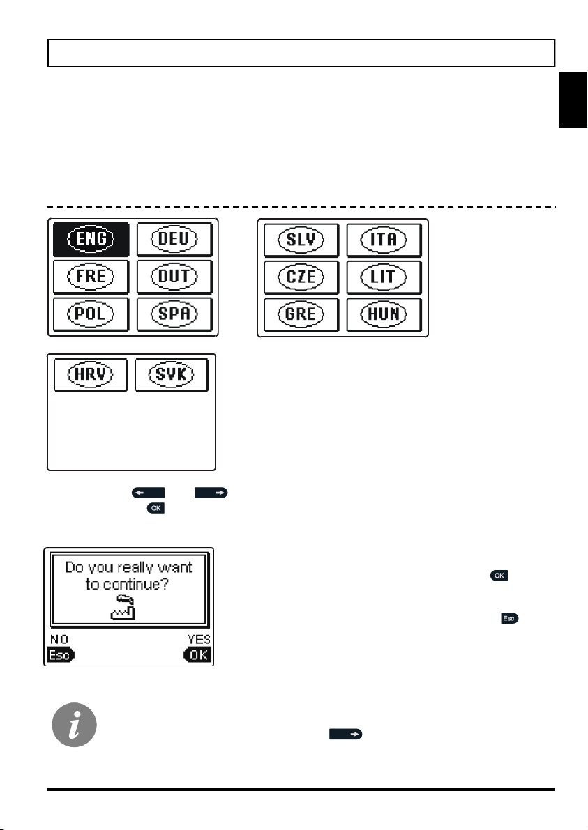
INITIAL CONTROLLER SETUP
SGC16H differential controllers are equipped with an innovative solution, which allows
initial setup of the controller in only two steps.
When you connect the controller to the power supply for the first time, the software ver-
sion is shown. Next, the first step appears on the screen.
Using buttons and you select the required language.
Press the button to confirm the selected language.
After selecting the language, the controller requires
confirmation of the selection by pressing the
button.
If you accidentally selected the wrong language, go
back to reset the language by pressing button .
If you cannot find the required language on the first screen, move to the fol-
lowing screens by pressing the button .
STEP 1
A1360_1
MJ/OD
06/2018
8
User and settings manual
ENG
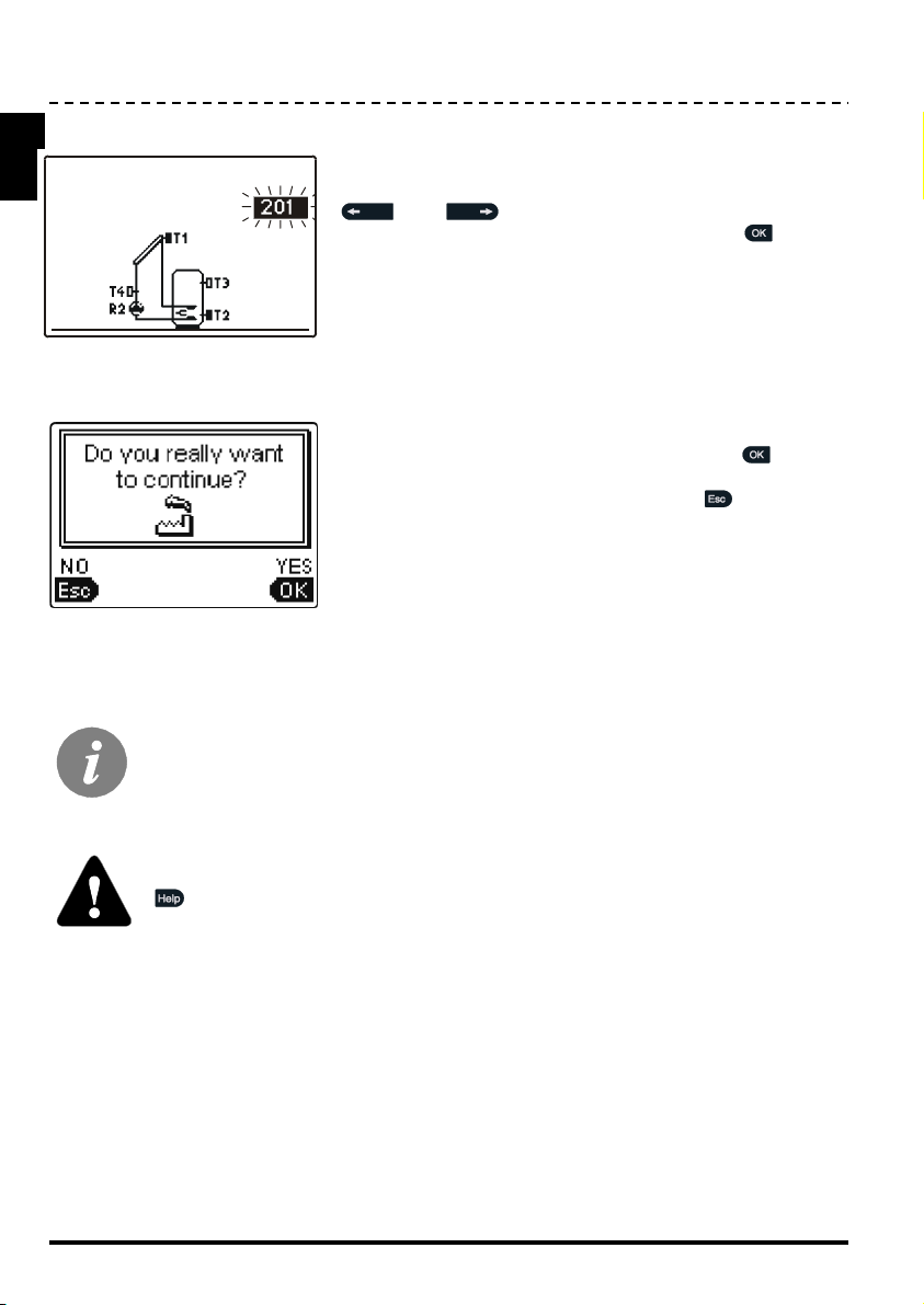
Selected hydraulic scheme can be later changed with service parameter S1.1.
Controller RESET!
Disconnect the controller from the power supply. Press and hold the button
and switch on power supply. The controller resets and goes to initial set-
up.
CAUTION!
By selecting ‘reset’ all previous controller settings are erased.
Next, you select a hydraulic scheme for the controller
function. Move between schemes by means of buttons
and .
Confirm the selected scheme by pressing the button.
STEP 2
After you selected the scheme, the controller requires
confirmation of the selection by pressing the button.
If you accidentally selected the wrong scheme, go back
to reset the scheme by pressing button .
A1360_1
MJ/OD
06/2018

9User and settings manual
ENG
Controller mode
Active time program
Active functions
Measured
temperatures,
state of output
and other data
Time
and
date
All important data of controller operation are shown on the graphic LCD display.
Advanced review of temperatures:
Measured temperature
Set point temperature
DESCRIPTION AND DESIGN OF THE MAIN DISPLAY:
For temperature and other data review we use buttons and .
Number of sensors and other data seen on the display depends on the selected hydraulic
scheme and controller settings.
2s
Which data are shown on the basic display depends on the selected scheme.
If we want to change the displayed information, press button or
to select the required data and confirm it by holding button for 2 sec-
onds.
Warnings
State
of output
Diagram
of hydraulic
scheme
Measured
temperatures
Sensors, that aren’t required for the selected scheme and aren’t connected,
are indicated with symbol .
GRAPHIC LCD DISPLAY
A1360_1
MJ/OD
06/2018

10
User and settings manual
ENG
All important data about controller operation are seen on the LCD display.
We browse through data by means of buttons and . .
OPERATION MODE SYMBOLS
Symbol Description
Controller operates in automatic mode
Controller operates automatically according to program timer ,
, or . ON and OFF indicates status of the timer.
Manual operation mode
Controller is in Stand-by.
One-time warming of domestic hot water function is activated
Holiday mode function is activated
Return cooling of storage tank is activated
Protection against overheating of the solar collectors is activated
Protection against freezing of the solar collectors is activated
Protection against legionella is activated
State of output ON
OFF
Inverted operation of output
RPM stage indication for pump R2
Indication impulsive pump mode - tube collectors (Parameter S2.2)
DESCRIPTION OF SYMBOLS SHOWN ON THE DISPLAY
A1360_1
MJ/OD
06/2018

11 User and settings manual
ENG
TEMPERATURE AND OTHER DATA SYMBOLS
Symbol Description
Solar collectors’ temperature
Temperature of storage tank or heat accumulator - bottom
Temperature of storage tank or heat accumulator - top
Liquid fuel boiler temperature
Solid fuel boiler temperature
Stand- pipe or return- pipe temperature
Measured temperature
Set point or calculated temperature
T1, T2, T3, T4, T5 Temperature sensors T1, T2, T3, T4 und T5.
SYMBOLS FOR NOTICE AND WARNINGS
Symbol Description
Notice
In case of exceeding the maximum temperature or activation of pro-
tection function, the controller indicates the event with flashing symbol
on the display. If the maximum temperature is no longer exceeded or if
the protection function is turned off, a lited symbol indicates a recent
event.
Press to open the screen to check notifications.
Warning
In the event of sensor failure, pump error or flow sensor error, the
controller indicates the failure with flashing symbol on the display. If
the issue is resolved or no longer present, a lited symbol indicates a
recent event.
Press to open the screen for warnings.
A1360_1
MJ/OD
06/2018

12
User and settings manual
ENG
Delete warning and notification logs
Pressing this button will erase notification and warning log. All sensors that are
not connected will be deleted from the list of failures.
Note: Failures of sensors that are required for controller operation can
not be deleted.
Press button to open the screen for help, notices and warnings is opened.
Short manual
Short manual for use of the controller.
Controller version
Overview of controller type and software version.
Notices
Log of maximum temperatures exceeds and activated protection functions. By
pressing the buttons and move through the list of notifications.
Press to exit the list.
Warnings
Log of sensors, pump or flow meter failures.
By pressing the buttons and move through the list of warnings.
Press to exit the list.
DISPLAY FOR HELP, NOTICES AND WARNINGS
Available posibilities:
A1360_1
MJ/OD
06/2018
13 User and settings manual
ENG
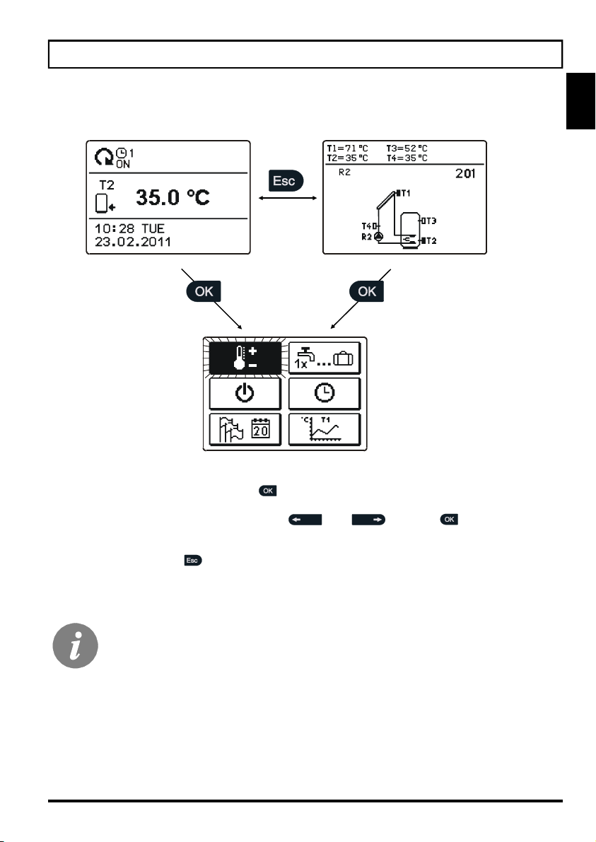
The menu is simplified with the help of graphic symbols.
To enter the menu, press the button .
Move around the menu using the buttons and , with the button you
confirm your selection.
By pressing the button you return to the previous screen.
If no button is pressed for several seconds, the screen illumination goes out.
In such case pressing any button switches on backlight illumination.
MENU ENTRY AND NAVIGATION
A1360_1
MJ/OD
06/2018

14
User and settings manual
ENG
MENU STRUCTURE AND DESCRIPTION
TEMPERATURE SETTINGS
Set-point temperature in d. h. w. storage tank or heat accumulator
USER FUNCTIONS
One - time domestic hot water warming
Holiday operation mode
Cancelation of user function
OPERATION MODE
Automatic operation
Controller operation - Stand-by
Manual operation mode
TIME PROGRAMS
SELECTION OF ACTIVE TIME PROGRAM
Without program timer
Program timer #1
Program timer #2
Program timer #3
Program timer #4
TIME PROGRAM EDITOR
Time program #1.
A1360_1
MJ/OD
06/2018

15 User and settings manual
ENG
Time program #2.
Time program #3.
Time program #4.
BASIC SETTINGS
Language selection
Time and date
DISPLAY SETTINGS
Duration of active display illumination and menu autoexit
Intensity of active display illumination
Intensity of inactive display illumination
Display contrast
DATA OVERVIEW
Numeric and graphic display of acquired energy
Diagrams of measured temperatures for last week
Diagrams of measured temperatures for current day
Output operation time counter
Special service data
BASIC PARAMETERS
Differences and hysteresis
Minimum and maximum temperatures
Parameters for protection against legionella
A1360_1
MJ/OD
06/2018
16
User and settings manual
ENG
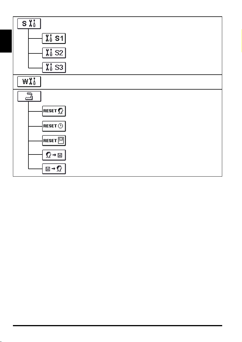
SERVICE PARAMETERS
Service parameters 1
Service parameters 2
Service parameters 3
PARAMETERS FOR HEAT METERING
FACTORY SETTINGS
Reset of all controller parameters
Reset of time programs
Reset of all controller settings and restart of initial setup
Save user settings
Load user settings
A1360_1
MJ/OD
06/2018
17 User and settings manual
ENG
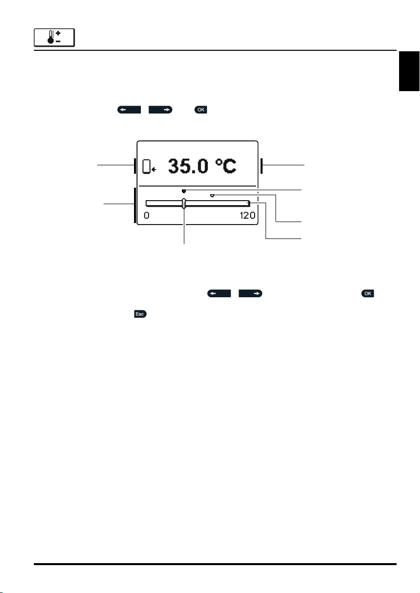
By pressing buttons , and you choose the required temperature, and a
new window opens:
Set the set-point temperature with buttons , and confirm with button .
Exit settings with button .
Graphic review
of settings
Sensor location
Value of the last
confirmed setting
Default value
Current value
of set-point temperature
(analogue mode)
Setting range
Current value
of set-point temperature
(numeric mode)
TEMPERATURE SETTINGS
In the menu “TEMPERATURE SETTINGS” you can set the set-point temperature for the sen-
sors shown.
A1360_1
MJ/OD
06/2018

18
User and settings manual
ENG
USER FUNCTIONS
User functions enable additional comfort and benefits when using the controller. In menu,
the following user functions are available:
One-time domestic hot water warming
One-time d. h. w. warming is possible only by scheme 203.
Use this function when you want to immediately turn on the d. h. w. warming.
By pressing buttons and select function and activate it by pressing the but-
ton .
You leave settings by pressing the button .
Holiday mode
Holiday mode is enabled only by scheme 201 and 203.
Holiday mode is used in cases of longer absence from home when there is no consump-
tion of hot water for longer period (several days).
Pump is activated if temperature of collectors T1 reaches P2.2 value and stays ON until
the temperature of collectors drops below the P2.2 plus hysteresis (P1.18) or until the tem-
perature of tank T2 reaches the P2.4 value. In the night time (but also in the day time),
when the collector temperature T1 drops 20 K below tank temperature T2, the pump is
activated again to cool the tank by circulating the liquid between hot tank and colder collec-
tors. The cooling process is active until the tank temperature T2 drops to P2.4 value or until
the temperature difference T2 - T1 is less than 15K.
Holiday mode is activated until selected date. After you have activated the Holiday mode,
choose the Holiday mode icon again. A new screen is displayed, where you can set the
date when the Holiday mode should be cancelled.
Each function can be at anytime cancelled by selecting icon .
Setting of PROTECTION OF MAX. COLLECTORS TEMPERATURE (S2.1)
and RECOOLING OF STORAGE TANK (S2.7) have no influence on Holi-
day mode operation.
The 20 K and 15 K temperature differences apply only if you do not change
the original factory setting. Generally, T cooling ON = P1.1+10 K and
T cooling OFF = P1.2+10 K.
A1360_1
MJ/OD
06/2018
19 User and settings manual
ENG
OPERATION MODE SELECTION
In group “OPERATION MODE” select the required controller operation mode. You can select
between automatic mode, controller switch-off and manual mode.
Description of operation mode:
You choose the required mode by pressing buttons , and confirm it by press-
ing button .
You exit the setting by pressing button .
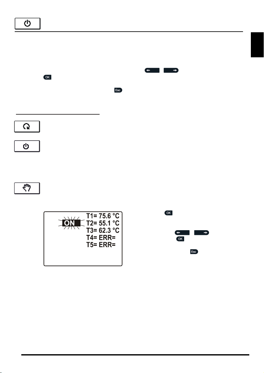
Automatic mode
Manual mode
This mode is used for testing the heating system or in case of a malfunction.
Every output can be manually activated or deactivated.
Press button . Value AUTO, OFF, 40 %,
55 %, 70 %, 85 % or ON starts to flash.
Now you can change the output state by
pressing buttons , and con-
firm it with button .
By pressing the button we exit settings.
Stand-by
Controller is not performing system control and switches off all outputs.
All temperatures are still measured and shown. Protection functions are still
active and able to switch on output.
R2 : ON
300 sec. to exit
A1360_1
MJ/OD
06/2018

20
User and settings manual
ENG
TIME PROGRAM SETTINGS
In menu “TIME PROGRAMS” you have two submenus - selection of active program timer
and program time editor .
Selection of active program timer
In the “SELECTION OF ACTIVE PROGRAM TIMER” menu are five settings:
WITHOUT PROGRAM TIMER
Controller operates without program timer.
PROGRAM TIMER #1
Controller operates according to program timer #1.
PROGRAM TIMER #2
Controller operates according to program timer #2.
PROGRAM TIMER #3
Controller operates according to program timer #3.
PROGRAM TIMER #4
Controller operates according to program timer #4.
Time program editor
In the “PROGRAM TIME EDITOR” menu we set or edit program time.
By pressing buttons , and select the program timer you want to edit or
modify. You can select between four program timers , , and .
A1360_1
MJ/OD
06/2018
Table of contents
Languages:
Other Thermo Solar Controllers manuals


Popular Controllers manuals by other brands

Toshiba
Toshiba Programmable Controller PROSEC T3 user manual

Faller
Faller 180725 instruction manual

Trane
Trane TRACER CH532 user guide

Federal Signal Corporation
Federal Signal Corporation SignalMaster 331105 SMC5 instructions

ADC
ADC AD-333 Service manual

Eaton
Eaton CGLine+ CGVision Series Quick installation manual


