Thermo Solar SGC36HV User manual
SGC36HV
ENG
Diferenčný regulátor
SGC36HV:
3
výstupy
, 6 v
stupov
, 2x ERP , 1x VFS
DEU
SVK
Differential controller
SGC36HV
: 3 outputs, 6 inputs, 2x ERP , 1x VFS
Differenzregler
SGC36HV:
3 Ausgänge, 6 Eingänge, 2x ERP , 1x VFS
A1343_3
MJ/OD
06/2018

A1343_3
MJ/OD
06/2018

E
N
G
D
E
U
S
V
K
Differential controllers
SGC36HV
Differenzregler
SGC36HV
Diferenčný regulátor
SGC36HV
A1343_3
MJ/OD
06/2018

A1343_3
MJ/OD
06/2018
E
N
G
5
INTUODUCTION
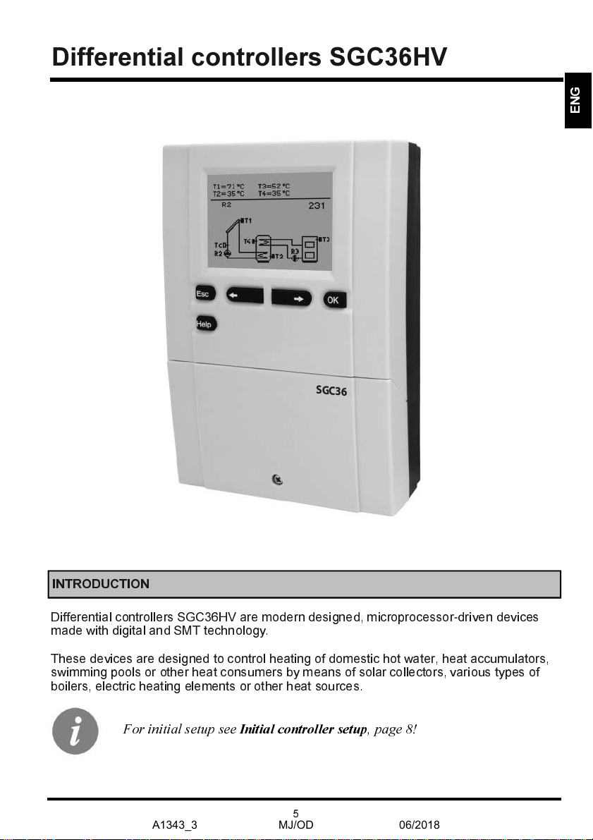
Differential controllers SGC36HV are modern designed, microprocessor
-
driven devices
made ith digital and SMT technology.
These devices are designed to control heating of domestic hot ater, heat accumulators,
s imming pools or other heat consumers by means of solar collectors, various types of
boilers, electric heating elements or other heat sources.
Differential controllers SGC36HV
For initial setup see
Initial controller setup
, page 8!
A1343_3
MJ/OD
06/2018

E
N
G
6
CONTENTS
USEU MANUAL
Appearance of controller SGC36HV
...........................................................................
7
Initial controller setup
..................................................................................................
8
Graphic LCD display
...............................................................................................
10
Description of symbols sho n on the display
..........................................................
11
Display for help, notices and arnings
......................................................................
13
Menu entry and navigation
......................................................................................
14
Menu structure and description
................................................................................
15
Temperature settings
...............................................................................................
18
User functions
.........................................................................................................
19
Operation mode selection
........................................................................................
20
Time program settings
.............................................................................................
21
Basic settings
...........................................................................................................
24
Data overvie
.........................................................................................................
26
SEUVICE MANUAL
Controller parameters and auxiliary tools
.................................................................
27
Basic parameters
.................................................................................................
27
Service parameters
.............................................................................................
30
Heat metering parameters
...................................................................................
34
Heat metering
........................................................................................................
34
Parameters for available outputs programming
.....................................................
36
Factory settings
.......................................................................................................
42
INSTALLATION MANUAL
Controller installation
...............................................................................................
43
Wall installation
........................................................................................................
43
Marking and description of temperature sensors
....................................................
44
Controller’s electric connection
.................................................................................
45
Flo meter installation
.............................................................................................
46
Temperature simulation mode
...................................................................................
46
Flo setuo and test of RPM control
..........................................................................
46
Technical data
...........................................................................................................
47
Declaration of conformity
...........................................................................................
48
Disposal of old electrical and electronic equipment
...................................................
49
Hydraulic and electric schemes
...............................................................................
142
Installation protocol
.................................................................................................
171
A1343_3
MJ/OD
06/2018

User and settings manual
E
N
G
7
SER MAN AL
APPERANCE OF CONTROLLER SGC36HV
Graphic display
Button
(Esc - return back)
Button (Help)
Button
(move to left, decreasing)
Screw for fastening the cover
Button
(menu entry, confirmation of selection)
2
1
3
5
4
6
7
8
Button
(move to right, increasing)
Cover for connection area
1
2
3
4
5
6
8
7
A1343_3
MJ/OD
06/2018
User and settings manual
E
N
G
8
INITIAL CONTUOLLEU SETUP
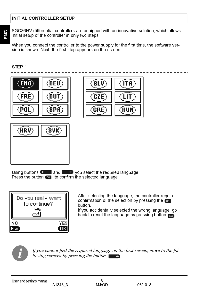
SGC36HV differential controllers are equipped ith an innovative solution, hich allo s
initial setup of the controller in only t o steps.
When you connect the controller to the po er supply for the first time, the soft are ver-
sion is sho n. Next, the first step appears on the screen.
Using buttons and you select the required language.
Press the button to confirm the selected language.
After selecting the language, the controller requires
confirmation of the selection by pressing the
button.
If you accidentally selected the rong language, go
back to reset the language by pressing button .
If you cannot find tee required language on tee first screen, move to tee fol-
lowing screens by pressing tee button .
STEP 1
A1343_3
MJ/OD
06/2018
User and settings manual
E
N
G
9
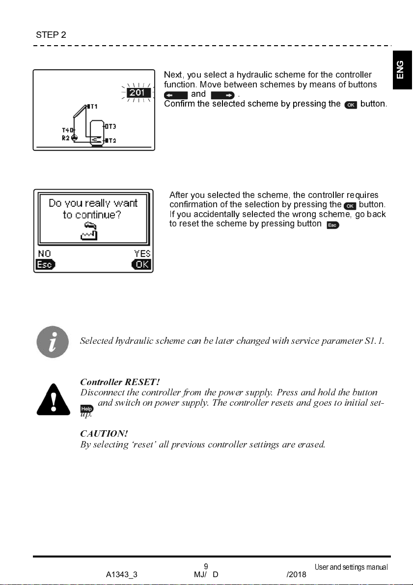
Selected eydraulic sceeme can be later ceanged wite service parameter S . .
Controller RE SET!
Disconnect tee controller from tee power supply. Press and eold tee button
and switce on power supply. Tee controller resets and goes to initial set-
up.
CAUTION!
By selecting ‘reset’ all previous controller settings are erased.
Next, you select a hydraulic scheme for the controller
function. Move bet een schemes by means of buttons
and .
Confirm the selected scheme by pressing the button.
STEP 2
After you selected the scheme, the controller requires
confirmation of the selection by pressing the button.
If you accidentally selected the rong scheme, go back
to reset the scheme by pressing button .
A1343_3
MJ/OD
06/2018
User and settings manual
E
N
G
10
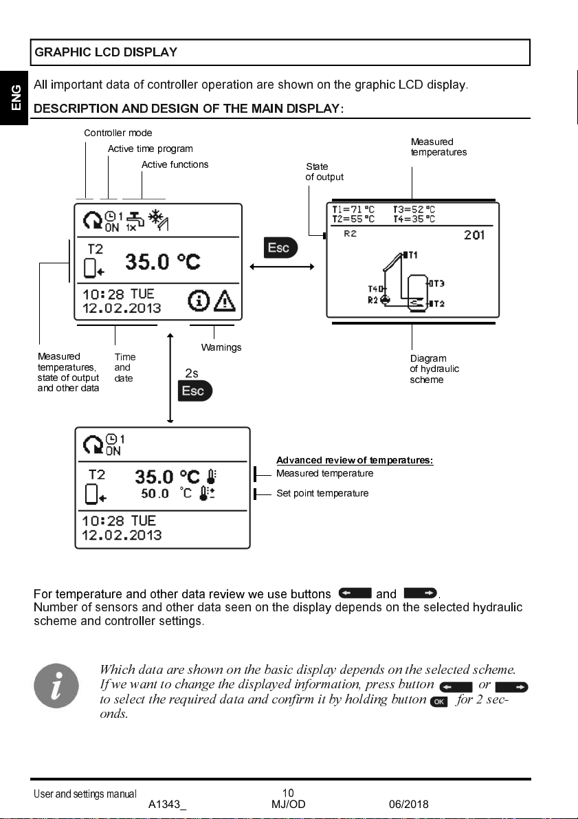
Controller mode
Active time program
Active functions
Measured
temperatures,
state of output
and other data
Time
and
date
All important data of controller operation are sho n on the graphic LCD display.
Advanced review of temperatures:
Measured temperature
Set point temperature
DESCRIPTION AND DESIGN OF THE MAIN DISPLAY:
For temperature and other data revie e use buttons and .
Number of sensors and other data seen on the display depends on the selected hydraulic
scheme and controller settings.
2s
Weice data are seown on tee basic display depends on tee selected sceeme.
If we want to ceange tee displayed information, press button or
to select tee required data and confirm it by eolding button for 2 sec-
onds.
Warnings
State
of outpu t
Diagram
of hydraulic
scheme
Measured
temperatures
GRAPHIC LCD DISPLAY
A1343_3
MJ/OD
06/2018

User and settings manual
E
N
G
11
All important data about controller operation are seen on the LCD displayz
We bro se through data by means of buttons and z z
OPERATION MODE SYMBOLS
DESCRIPTION OF SYMBOLS SHOWN ON THE DISPLAY
Symbol
D scription
Controller operates in automatic mode
Controller operates automatically according to program timer , ,
or z ON and OFF indicates status of the timerz
Manual operation mode
Controller is in Stand
-
by
One
-
time arming of domestic hot ater function is activated
Holiday mode function is activated
Return cooling of storage tank is activated
Protection against overheating of the solar collectors is activated
Protection against freezing of the solar collectors is activated
Protection against legionella is activated
State of outputs
-
If the output is displayed, it is ONz If the output is not
displayed, it is OFFz *
or
Output has a function programmed (parameters
F1
,
F2
)*
Pump speed (RPM stage) indication for R2 and R3*
Indication of impulse pump start mode for tube collectors (Parameter
S2z2)
Inverted operation of output
* Depends on the controller model.
A1343_3
MJ/OD
06/2018

User and settings manual
E
N
G
12
TEMPEUATUUE AND OTHEU DATA SYMBOLS
SYMBOLS FOU NOTICE AND WAUNINGS
Symbol
D scription
Notic
In case of exceeding the maximum temperature or activation of pro-
tection function, the controller indicates the event ith flashing symbol
on the display. If the maximum temperature is no longer exceeded or if
the protection function is turned off, a lited symbol indicates a recent
event.
Press to open the screen to check notifications.
Warning
In the event of sensor failure, pump error or flo sensor error, the
controller indicates the failure ith flashing symbol on the display. If
the issue is resolved or no longer present, a lited symbol indicates a
recent event.
Press to open the screen for arnings.
Symbol D scription
Solar collectors temperature
Temperature of storage tank or heat accumulator
-
bottom
Temperature of storage tank or heat accumulator
-
top
Liquid fuel boiler temperature
Solid fuel boiler temperature
Pellet boiler temperature
Outdoor temperature
S imming pool ater temperature
Stand
-
pipe or return
-
pipe temperature
Measured temperature
Set point or calculated temperature
T1, T2, T3, T4, T5, T6
Temperature sensors T1, T2, T3, T4, T5 and T6
A1343_3
MJ/OD
06/2018

User and settings manual
E
N
G
13
D l t warning and notification logs
Pressing this button ill erase notification and arning log. All sensors that
are not connected ill be deleted from the list of failures.
Not :
Failures of sensors that are required for controller operation can
not be deleted.
Press button to open the screen for help, notices and arnings is opened.
Short manual
Short manual for use of the controller.
Controll r v rsion
Overvie of controller type and soft are version.
Notic s
Log of maximum temperatures exceeds and activated protection functions.
By pressing the buttons and move through the list of notifica-
tions. Press
to exit the list.
Warnings
Log of sensors, pump or flo meter failures.
By pressing the buttons and move through the list of arnings.
Press
to exit the list.
DISPLAY FOR HELP, NOTICES AND WARNINGS
Available posibilities:
A1343_3
MJ/OD
06/2018
User and settings manual
E
N
G
14
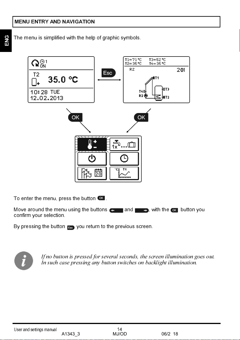
The menu is simplified ith the help of graphic symbols.
To enter the menu, press the button .
Move around the menu using the buttons and , ith the button you
confirm your selection.
By pressing the button you return to the previous screen.
If no button is pressed for several seconds, tee screen illumination goes out.
In suce case pressing any button switcees on backliget illumination.
MENU ENTUY AND NAVIGATION
A1343_3
MJ/OD
06/2018

User and settings manual
E
N
G
15
MENU STUUCTUUE AND DESCUIPTION
TEMPERATURE SETTINGS
Set-point temperature in d. h. w. storage tank or heat accumulator - bottom*
Desired temperature of domestic hot water tank or heat accumulator - top*
Desired swimming pool water temperature
Desired return-pipe temperature
USER FUNCTIONS
One - time domestic hot water warming
Holiday operation mode
Cancelation of user function
OPERATION MODE
Automatic operation
Stand-by
Manual mode
TIME PROGRAMS
SELECTION OF ACTIVE TIME PROGRAM
Without time program
Time program #1
Time program #2
*
The “n” sym ol marks the successive num er of d. h. w. storage tank or heat accumulator, if there is more than
one d. h. w. storage tank or heat accumulator present in the system. The “Tx” sym ol marks the num er of the
sensor for which the thermostatic operation of the availa le output is prog rammed.
A1343_3
MJ/OD
06/2018

User and settings manual
E
N
G
16
Time program #3
Time program #4
TIME PROGRAM EDITOR
Time program #1
Time program #2
Time program #3
Time program #4
BASIC SETTINGS
Language selection
Time and date
Duration of active display illumination and menu autoexit
Intensity of active display illumination
Intensity of inactive display illumination
Display contrast
DATA OVERVIEW
Numeric and graphic display of acquired energy
Diagrams of measured temperatures for last week
Diagrams of measured temperatures for current day
Output operation time counter
Special service data
DISPLAY SETTINGS
A1343_3
MJ/OD
06/2018
User and settings manual
E
N
G
17
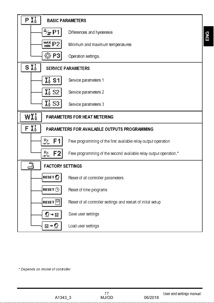
BASIC PARAMETERS
Differences and hysteresis
Minimum and maximum temperatures
Operation settings.
SERVICE PARAMETERS
Service parameters 1
Service parameters 2
Service parameters 3
PARAMETERS FOR HEAT METERING
PARAMETERS FOR AVAILABLE OUTPUTS PROGRAMMING
Free programming of the first available relay output operation
Free programming of the second available relay output operation.*
FACTORY SETTINGS
Reset of all controller parameters
Reset of time programs
Reset of all controller settings and restart of initial setup
Save user settings
Load user settings
* Depends on model of controller.
A1343_3
MJ/OD
06/2018
User and settings manual
E
N
G
18
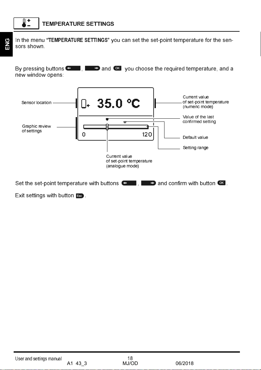
By pressing buttons , and you choose the required temperature, and a
ne indo opens:
Set the set
-
point temperature ith buttons , and confirm ith button .
Exit settings ith button .
Graphic review
of setting s
Sensor location
Value of the last
confirmed setting
Default value
Current value
of set
-
point tem perature
(analogue mode)
Setting range
Current value
of set
-
point tem perature
(numeric mode)
TEMPEUATUUE SETTINGS
In the menu
“TEMPERATURE SETTINGS”
you can set the set
-
point temperature for the sen-
sors sho n.
A1343_3
MJ/OD
06/2018

User and settings manual
E
N
G
19
USEU FUNCTIONS
User functions enable additional comfort and benefits hen using the controller. In menu,
the follo ing user functions are available:
On
-
tim dom stic hot wat r warming
One
-
time d. e. w. warming is possible only by sceemes wite a liquid fuel
boiler, eeat pump or electric eeater.
Use this function hen you ant to immediately turn on the d. h. . arming.
By pressing buttons and select function and activate it by pressing the but-
ton .
You leave settings by pressing the button .
Holiday mode is enabled in sceemes wite solar collectors, liquid fuel boiler,
eeat pump or electric eeater.
Holiday mod
Holiday mode is used in cases of longer absence from home hen there is no consump-
tion of hot ater for longer period (several days).
Pump is activated if temperature of collectors T1 reaches P2.2 value and stays ON until
the temperature of collectors drops belo the P2.2 plus hysteresis (P1.18) or until the tem-
perature of tank T2 reaches the P2.4 value. In the night time (but also in the day time),
hen the collector temperature T1 drops 20 K belo tank temperature T2, the pump is
activated again to cool the tank by circulating the liquid bet een hot tank and colder collec-
tors. The cooling process is active until the tank temperature T2 drops to P2.3 value or until
the temperature difference T2
-
T1 is less than 15K.
Holiday mode is activated until selected date. After you have activated the Holiday mode,
choose the Holiday mode icon again. A ne screen is displayed, here you can set the
date hen the Holiday mode should be cancelled.
Eace function can be at anytime cancelled by selecting icon .
Setting of PROTECTION OF MAX. COLLECTORS TE MPERATURE (S2. )
and RECOOLING OF STORAGE TANK (S2.7) eave no influence on Holi-
day mode operation.
Tee 20 K and 5 K temperature differences apply only if you do not ceange
tee original factory setting. Generally, T
coolino ON
= P . + 0 K and
T
coolino OFF
= P .2+ 0 K.
A1343_3
MJ/OD
06/2018
User and settings manual
E
N
G
20
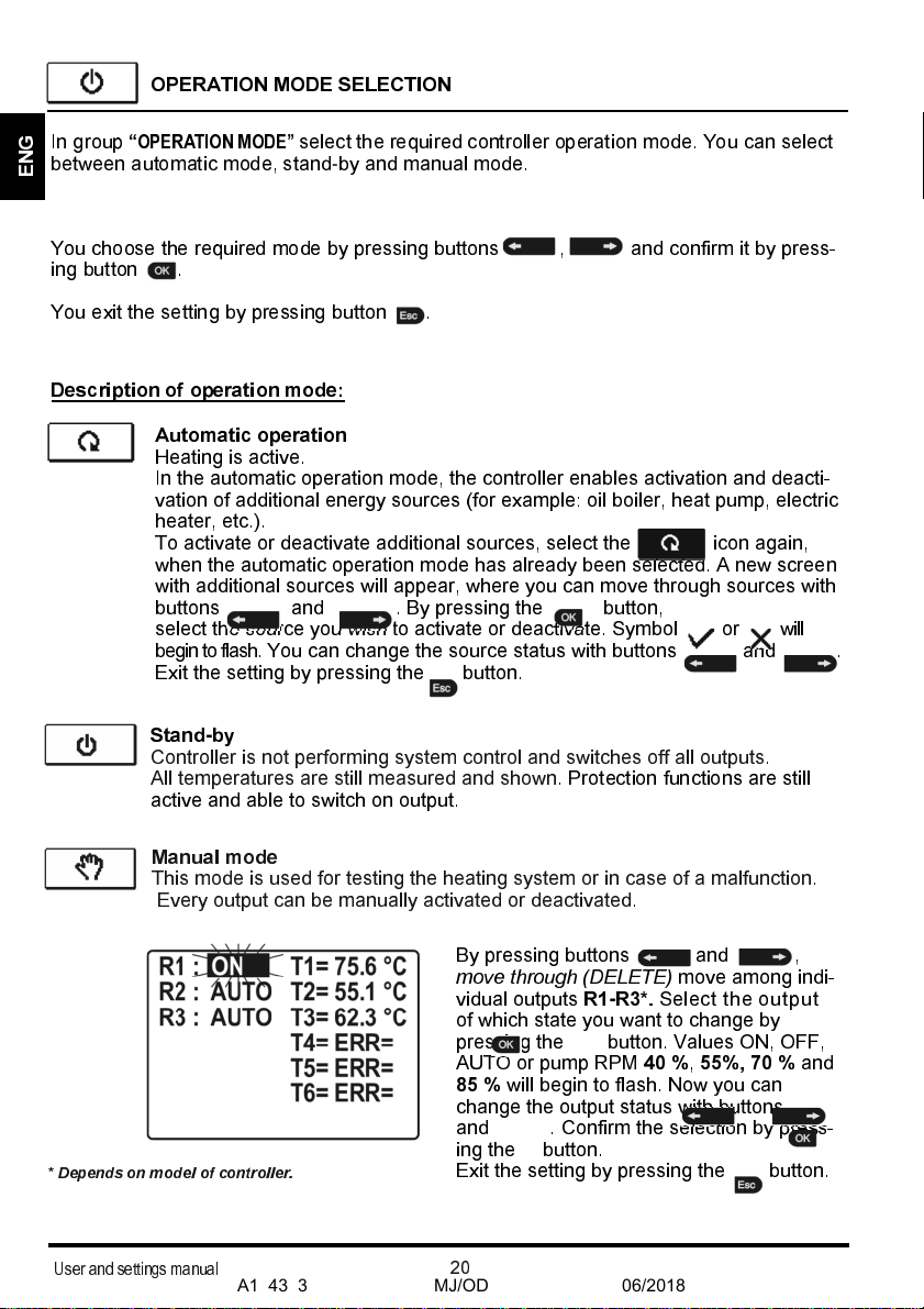
OPERATION MODE SELECTION
In group
“OPERATION MODE”
select the required controller operation mode. You can select
bet een automatic mode, stand
-
by and manual mode.
D scription of op ration mod :
You choose the required mode by pressing buttons , and confirm it by press-
ing button .
You exit the setting by pressing button .
Manual mod
This mode is used for testing the heating system or in case of a malfunction.
Every output can be manually activated or deactivated.
By pressing buttons and ,
move through (DELETE)
move among indi-
vidual outputs
R1
-
R3*.
Select the output
of hich state you ant to change by
pressing the button. Values ON, OFF,
AUTO or pump RPM
40 %
,
55%, 70 %
and
85 %
ill begin to flash. No you can
change the output status ith buttons
and .
Confirm the selection by press-
ing the button.
Exit the setting by pressing the button.
Stand
-
by
Controller is not performing system control and s itches off all outputs.
All temperatures are still measured and sho n. Protection functions are still
active and able to s itch on output.
Automatic op ration
Heating is active.
In the automatic operation mode, the controller enables activation and deacti-
vation of additional energy sources (for example: oil boiler, heat pump, electric
heater, etc.).
To activate or deactivate additional sources, select the icon again,
hen the automatic operation mode has already been selected. A ne screen
ith additional sources ill appear, here you can move through sources ith
buttons and . By pressing the button,
select the source you ish to activate or deactivate. Symbol or ill
begin to flash. You can change the source status ith buttons and .
Exit the setting by pressing the button.
* Depends on model of controller.
A1343_3
MJ/OD
06/2018
Other manuals for SGC36HV
1
Table of contents
Languages:
Other Thermo Solar Controllers manuals


Popular Controllers manuals by other brands


Excelitas Technologies
Excelitas Technologies OmniCure SC Series Installation reference guide

Nexmosphere
Nexmosphere XPERIENCE XN-125 quick start guide

AKO
AKO AKO-14545 user manual

Timken
Timken ROLLON ECO Series Use and maintenance

Mitsubishi Electric
Mitsubishi Electric QS001CPU user manual

Scion-Tech
Scion-Tech SC08.CTL100 user manual