manuals.online logo
Brands
  1. Home
  2. •
  3. Brands
  4. •
  5. Siemens
  6. •
  7. Controllers
  8. •
  9. Siemens UP 520/31 User manual

Siemens UP 520/31 User manual

Other Siemens Controllers manuals
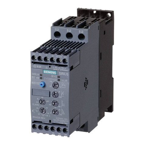
Siemens SIRIUS 3RW30 User manual

Siemens

Siemens SIRIUS 3RW30 User manual

Siemens RWD62U Owner's manual

Siemens

Siemens RWD62U Owner's manual

Siemens BT300 LonWorks Instructions for use

Siemens

Siemens BT300 LonWorks Instructions for use

Siemens L-828 User manual

Siemens

Siemens L-828 User manual

Siemens OpenAir GDE131.1U User manual

Siemens

Siemens OpenAir GDE131.1U User manual

Siemens SKP Series Owner's manual

Siemens

Siemens SKP Series Owner's manual

Siemens SINAMICS S120 User manual

Siemens

Siemens SINAMICS S120 User manual

Siemens FDV241 Installation and operation manual

Siemens

Siemens FDV241 Installation and operation manual

Siemens SIKOSTART 3RW34 Manual

Siemens

Siemens SIKOSTART 3RW34 Manual

Siemens TIM 1531 IRC User manual

Siemens

Siemens TIM 1531 IRC User manual
Siemens GIB 1 Series User manual

Siemens

Siemens GIB 1 Series User manual

Siemens SIMATIC S5 Series User manual

Siemens

Siemens SIMATIC S5 Series User manual

Siemens RVD230 Operator's manual

Siemens

Siemens RVD230 Operator's manual

Siemens 7SR224 Use and care manual

Siemens

Siemens 7SR224 Use and care manual

Siemens SICAM TM User manual

Siemens

Siemens SICAM TM User manual

Siemens SIMOTION P320-4 E User manual

Siemens

Siemens SIMOTION P320-4 E User manual

Siemens PS 307 6ES7307-1BA01-0AA0 User manual

Siemens

Siemens PS 307 6ES7307-1BA01-0AA0 User manual

Siemens GBB 2 Series User manual

Siemens

Siemens GBB 2 Series User manual

Siemens RVL481 User manual

Siemens

Siemens RVL481 User manual

Siemens RWD68U Owner's manual

Siemens

Siemens RWD68U Owner's manual

Siemens GNA 1E Series User manual

Siemens

Siemens GNA 1E Series User manual

Siemens SINUMERIK 840D sl User manual

Siemens

Siemens SINUMERIK 840D sl User manual

Siemens RAJA+ 3TE7 DOL Guide

Siemens

Siemens RAJA+ 3TE7 DOL Guide

Siemens BT300 LonWorks User manual

Siemens

Siemens BT300 LonWorks User manual

Popular Controllers manuals by other brands

Sunricher SR-ZV9003T3-RGBW-US Installation

Sunricher

Sunricher SR-ZV9003T3-RGBW-US Installation

Ksenia intro Installation and configuration manual

Ksenia

Ksenia intro Installation and configuration manual

Inovance CAN200 Series manual

Inovance

Inovance CAN200 Series manual

Gauzy LC6 FLEX Controller Installation and operation guide

Gauzy

Gauzy LC6 FLEX Controller Installation and operation guide

Viking SLP-1 Technical practice

Viking

Viking SLP-1 Technical practice

CKD KBX-30E-U Series instruction manual

CKD

CKD KBX-30E-U Series instruction manual

Sharp Energy Sun Flux User manual & installation guide

Sharp Energy

Sharp Energy Sun Flux User manual & installation guide

Yamaha RCX40 user manual

Yamaha

Yamaha RCX40 user manual

AB Quality PowerFlex 400 Frames D-H Service bulletin

AB Quality

AB Quality PowerFlex 400 Frames D-H Service bulletin

Yamaha MJC8 owner's manual

Yamaha

Yamaha MJC8 owner's manual

AL-KO ATC operating instructions

AL-KO

AL-KO ATC operating instructions

Savant SmartControl 2 Deployment guide

Savant

Savant SmartControl 2 Deployment guide

GameSir T3S user manual

GameSir

GameSir T3S user manual

Kostal inveor operating manual

Kostal

Kostal inveor operating manual

Emerson Yarway 20-55 Operating and safety instructions

Emerson

Emerson Yarway 20-55 Operating and safety instructions

CoCo ACM-LV24 Quick installation guide

CoCo

CoCo ACM-LV24 Quick installation guide

Brooks SLA5810/20 Installation and operation manual

Brooks

Brooks SLA5810/20 Installation and operation manual

SIGMA TEK SR 011 Technical manual

SIGMA TEK

SIGMA TEK SR 011 Technical manual

manuals.online logo
manuals.online logoBrands
  • About & Mission
  • Contact us
  • Privacy Policy
  • Terms and Conditions

Copyright 2025 Manuals.Online. All Rights Reserved.

GAMMA instabus
Technical Product Information
February 2010
Blind actuator UP 520/31 5WG1 520-2AB31
Siemens AG UP 520/31, 4 pages Technical Manual
Industry Sector, Building Technologies
Low Voltage Distribution © Siemens AG 2010 Update: http://www.siemens.com/gamma
PO Box 10 09 53, D-93009 Regensburg Subject to change without further notice
2.10.1.18/1
Product and Function Description
Photo
The blind actuator receives telegrams from sensors via the
Instabus and controls a shutter or blind motor with its
output. Both travel directions are mechanically
interlocked. With sun protection or positioning telegrams,
the actuator offers moreover the possibility of moving
shutters, blinds and slats into any desired position. On
reception of a storm warning, the actuator is capable of
moving shutters or blinds into a predefined safety position
and to lock them up in this position.
In addition, the device has two extension inputs that
depending on parameter settings, can act directly on the
output (local operation, see “state of delivery”) or
alternatively also as binary inputs on the Instabus. The
connected potential-free switch or push button contacts
are read in via a common reference potential on the
actuator. As binary input, telegrams can be transmitted for
switching or dimming, for Venetian blind control, value
setting or scene recall / save.
State of delivery:
•When delivered, the switching state of the outputs is
undefined.
•On application of the bus voltage, the relays will switch
off.
•With the bus voltage applied, the extension inputs
control the relays of the actuator as follows:
input Operation behavior
short stop / slat up
A long move up
short stop / slat down
B long move down
Simultaneous actuation of A and B is not possible
Application program
12 A1S2 Shutter, 2x Input 207301
•2 binary inputs
oON / OFF / TOGGLE switching
oValue setting
oDimming
oBlind / Shutter – control
oScene control
oInputs blocking function
oBehavior on bus power restoration
•1 channel with additional functions
oSun protection function
oSafety function
oAdjustable response after bus voltage
failure
oAdjustable response to bus voltage return
oAdjustable priority of sun protection
function and manual operation
GAMMA instabus
Technical Product Information
February 2010
Blind actuator UP 520/31 5WG1 520-2AB31
Technical Manual UP 520/31, 4 pages Siemens AG
Industry Sector, Building Technologies
Update: http://www.siemens.com/gamma © Siemens AG 2010 Low Voltage Distribution
Subject to change without further notice PO Box 10 09 53, D-93009 Regensburg
2.10.1.18/2
Technical specifications
Power supply
•Carried out via the bus line
•Power consumption: typically 150 mW
Outputs
•Number: 1 output, potential-free relay contact (µ-contact)
•Rating voltage: AC 230V,
•Switching power: max. 1 motor 1000 VA
•Switching behavior: Can be parameter set, depending
on function
Contacts
•Output: Contact the load on H07V-K 1,5 mm2with the
attached clamps.
•Inputs and bus line: Line YY 6x0.6 mm
Approx. 33cm pre-assembled, can be laid to max. 5m
Mechanical specifications
•Casing: plastic
•Dimensions: d =53mm, height = 28 mm
•Weight: approx. 88g
•Mounting: in box mounts, Ø 60mm, depth: 40mm
Electrical safety
•Degree of pollution (to IEC 60664-1): 2
•Protection class (to EN 60529): IP 20
•Protection class (to IEC 61140): III
•Overvoltage category class (to IEC 60664-1): III
•Bus: safety extra low voltage SELV DC 24V
•Device complies with EN 50090-2-2 and IEC 60664-1
Reliability
Failure rate: 170 fit at 40°C
EMC criteria
•Complies with EN 61000-6-2, EN 61000-6-3 and EN
50090-2-2
Environmental specifications
•Climatic conditions: EN 50090-2-2
•Ambient temperature in operation: - 5 ... + 45 °C
•Storage temperature: - 25 ... + 70 °C
(Storage above + 45°C reduces the service life)
•Relative humidity (non-condensing): 5% to 93%
Markings
•KNX EIB
CE mark
•to EMC directive (residential and functional building)
Location and functioning of the display and
operating elements
PKBK
EIB+ / RD
EIB- / BK
A / GN
com / WH
B / YE
com / BN
Prog.
U 230V
n
~
Figure 1: Location of the indicating and operating elements
X Connector cables low voltages
Red: Bus (+)
Black: Bus (-)
Green: input A
White: Reference potential (com)
Yellow: Input B
Brown: Reference potential (com)
Y Connector cables load
black: L // brown: Up // pink: Down
Z Program button / -LED (red)
GAMMA instabus
Technical Product Information
February 2010
Blind actuator UP 520/31 5WG1 520-2AB31
Siemens AG UP 520/31, 4 pages Technical Manual
Industry Sector, Building Technologies
Low Voltage Distribution © Siemens AG 2010 Update: http://www.siemens.com/gamma
PO Box 10 09 53, D-93009 Regensburg Subject to change without further notice
2.10.1.18/3
Mounting and wiring
ÆGeneral:
It is recommended that the actuator is installed in two
flush sockets connected to one another (cf. fig. 2). One
socket (A) can accommodate, e.g., a series switch (C) as
well as the bus and extension connection. The other
socket (B) accommodates the actuator and the 230 V
terminals. The 6-pole connection lead (D) is guided
through the socket connection.
A
230 V
B
C
D
Figure 2
230 V
Bus/Com/A,B
> 4 mm
Figure 3
VDanger
•The device must be mounted and commissioned
by an authorized electrician.
•When connecting the device, it should be
ensured that the device can be isolated.
•The device must not be opened.
•For planning and construction of electric
installations, the relevant guidelines, regulations
and standards of the respective country are to be
considered.
•During installation, ensure adequate insulation
between mains voltage and bus or extensions! A
minimum spacing should be maintained
between bus / extension cable cores and mains
voltage cable cores of at least 4 mm.
(cf. figure 3)
ÆInputs:
Two extension inputs can be used for the connection of
potential-free contacts for local control or as binary inputs.
(cf. figure 4)
Line YY 6x 0.6 mm
Approx. 33cm pre-assembled, can be laid to max. 5m
COM
COM
A
B
U = - 19 V (ca./approx.)
com
UCOM
UCOM
rot / red
schwarz / black
grün / green
weiß / white
gelb / yellow
braun / brown
KNX
A
B
(-)
(+)
Figure 4
Caution
•To avoid disruptive EMI irradiation, the lines of the
inputs should not be laid parallel to lines conducting
mains voltage.
•Input A (green), input B (yellow) and reference
potential (com) (white and brown) must not
connect to inputs or reference potential (com) of
other devices.
VDanger
•On no account should you connect mains voltage
(230 V) or other external voltages to the extension
inputs! Connection to an external voltage would
endanger the electrical safety of the entire KNX/EIB
system (SELV / no galvanic isolation)!
People can be at risk, equipment and devices can be
destroyed!
•Unused cable cores of the 6-pole connection lead
are to be insulated from one another and from
external voltages.
GAMMA instabus
Technical Product Information
February 2010
Blind actuator UP 520/31 5WG1 520-2AB31
Technical Manual UP 520/31, 4 pages Siemens AG
Industry Sector, Building Technologies
Update: http://www.siemens.com/gamma © Siemens AG 2010 Low Voltage Distribution
Subject to change without further notice PO Box 10 09 53, D-93009 Regensburg
2.10.1.18/4
ÆOutputs:
A blind actuator is switching an electrical drive, which is
configured for two rotating directions (Up/Down). (cf.
figure 5)
M
L1
L2
L3
N
µ
µ
PKBNBK
L
EIB+ / RD
EIB- / BK
A / GN
com / WH
B / YE
com / BN
Prog.
Un~ 230V
Figure 5
Note
•The outputs of the blind actuator are electrical
interlocked
VDanger
•The soldered end of lines have to connect by using
the attached clamps.
•Do not connect three-phase AC motors to blind
actuators
•Observe the instructions of the motor
manufacturers if motors are to be connected in
parallel. Otherwise risk of irreparable damage to
the motors.
•Use only blinds or shutters with limit switches
(mechanical or electronic). The limit switches of
the connected motors must be checked for correct
adjustment.
Dimensioned picture
Dimensions in mm
Figure 6
Ø = 53 mm
Height = 28 mm
General notes
•Any faulty device is to be returned to the local Siemens
office.
•If you have further questions concerning the product,
please contact our Technical Support:
℡+49 (0) 180 50 50-222 (0,14 €/min. from the German
landline network, deviating mobile communications
prices are possible)
+49 (0) 180 50 50-223
E-Mail: support.automation@siemens.com
Internet: www.siemens.com/automation/service&support