Thermo-Star Denta-Star S1 User manual
Original instruction manual
Denta-Star S1
Atmospheric sintering furnace for
sintering of oxide ceramics
Please read this instruction manual carefully and if
necessary other documents related to the product to ensure
safe and proper application.
The manual must be given to the end user who should keep
it throughout the service life until disposal.

- 2 -
WELCOME
Thermo-Star GmbH (hereafter referred to as Thermo-Star) appreciates your
confidence and delivers to you a sintering furnace (hereafter referred to as
furnace).
The furnace was subjected to a complete functional test prior to dispatch and the
packaging content was checked for completeness.
The figures and illustrations used in this document contribute to basic understanding
and may be different from the product design.
You can find a list of tables and illustrations in the Appendix.
2. edition, status January 2018
Thermo-Star GmbH
Krantzstr. 7 / Geb. 37
52070 Aachen, Germany
Phone: +49 241 60845-0
Fax: +49 241 60845-100
www.thermo-star.de

- 3 -
TABLE OF CONTENTS
1INTRODUCTION............................................................................................................. 5
1.1 SERVICE ................................................................................................................................... 5
1.2 STATUTORY DEFECTS LIABILITY............................................................................................... 5
1.3 SYMBOLS USED IN THIS INSTRUCTION MANUAL..................................................................... 5
2SAFETY INFORMATION .................................................................................................. 6
2.1 INTENDED USE......................................................................................................................... 6
2.1.1 SCOPE...................................................................................................................................... 6
2.1.2 IMPROPER USE........................................................................................................................ 6
2.2 QUALIFIED PERSONS ............................................................................................................... 7
2.3 PERSONAL PROTECTIVE EQUIPMENT...................................................................................... 8
2.4 DEPICTION OF WARNINGS ...................................................................................................... 9
2.5 UNAUTHORIZED PARTS........................................................................................................... 9
2.6 GENERAL HAZARDOUS POTENTIAL ....................................................................................... 10
2.6.1 THERMAL HAZARD ................................................................................................................ 10
2.7 ELECTROMAGNETIC COMPATIBILITY .................................................................................... 10
2.8 RESPONSIBILITY OF THE OWNER........................................................................................... 11
3TRANSPORT AND STORAGE ......................................................................................... 12
3.1 SAFE TRANSPORT AND STORAGE .......................................................................................... 12
3.2 TRANSPORT........................................................................................................................... 13
3.3 STORAGE ............................................................................................................................... 13
4DESCRIPTION OF THE PRODUCT................................................................................... 14
4.1 SCOPE OF SUPPLY.................................................................................................................. 14
4.2 PRODUCT CHARACTERISTICS................................................................................................. 15
4.2.1 SHORT DESCRIPTION OF THE FURNACE................................................................................ 15
4.2.2 CHARACTERISTICS AND TECHNICAL DATA............................................................................ 15
4.3 COMPONENTS....................................................................................................................... 16
4.4 FUNCTIONALITY .................................................................................................................... 17
4.5 TYPE PLATE............................................................................................................................ 17
4.6 ACCESSORIES......................................................................................................................... 17
5INSTALLATION............................................................................................................. 18
5.1 SAFE INSTALLATION .............................................................................................................. 18
5.2 INSTALLING THE FURNACE .................................................................................................... 19
5.2.1 LOCATION.............................................................................................................................. 19
5.2.2 SETTING UP THE FURNACE.................................................................................................... 19
5.2.3 MOUNTING HEATING ELEMENTS ......................................................................................... 20
5.2.4 ELECTRICAL CONNECTION..................................................................................................... 21
6FIRST PUTTING INTO SERVICE AND USE........................................................................ 22
6.1 SAFE FIRST PUTTING INTO SERVICE AND USE........................................................................ 22
6.2 PUTTING INTO SERVICE......................................................................................................... 22
6.2.1 OPERATIONAL CONDITION ................................................................................................... 22
6.2.2 FIRST LOADING THE FURNACE.............................................................................................. 23
6.2.3 UNLOADING THE FURNACE................................................................................................... 24
6.2.4 RELOADING THE FURNACE.................................................................................................... 24
6.2.5 FURNACE EMERGENCY STOP ................................................................................................ 24

- 4 -
7OPERATION................................................................................................................. 25
7.1 GENERAL FURNACE OPERATION ........................................................................................... 25
7.1.1 OPENING AND CLOSING THE FURNACE ................................................................................ 25
7.1.2 CONTROLLER COMPONENTS ................................................................................................ 26
7.1.3 SELECTING A PROGRAM........................................................................................................ 26
7.1.4 SEGMENT FUNCTIONS .......................................................................................................... 27
7.2 PROGRAMMING THE CONTROLLER ...................................................................................... 28
7.2.1 PROGRAMMING SEGMENTS................................................................................................. 28
7.2.2 SEGMENT FUNCTIONS .......................................................................................................... 28
7.2.3 EXAMPLE PROGRAMMING ................................................................................................... 30
8MAINTENANCE............................................................................................................ 32
8.1 SAFE MAINTENANCE ............................................................................................................. 32
8.2 FURNACE MANUAL ............................................................................................................... 33
8.3 MAINTENANCE WORK FOR THE USER................................................................................... 33
8.3.1 DAILY CONTROLS................................................................................................................... 33
8.3.2 MAINTENANCE WORK AS NEEDED ....................................................................................... 33
8.3.3 REGULAR MAINTENANCE WORK .......................................................................................... 33
9TROUBLESHOOTING .................................................................................................... 34
9.1 SAFE TROUBLESHOOTING ..................................................................................................... 34
9.2 FAULT FINDING...................................................................................................................... 34
10 REPAIR........................................................................................................................ 35
10.1 SAFE REPAIR .......................................................................................................................... 35
10.2 REPLACING HEATING ELEMENTS........................................................................................... 35
10.3 OTHER REPAIRS &SPARE PARTS............................................................................................ 35
11 TAKING OUT OF SERVICE & DISPOSAL .......................................................................... 36
11.1 SAFE TAKING OUT OF SERVICE .............................................................................................. 36
11.2 TAKING OUT OF SERVICE....................................................................................................... 37
11.3 SHUTDOWN .......................................................................................................................... 37
11.4 DISPOSAL............................................................................................................................... 37
12 DECLARATION OF CONFORMITY .................................................................................. 38
13 APPENDIX ................................................................................................................... 39
13.1 INDEX OF TABLES................................................................................................................... 39
13.2 INDEX OF ILLUSTRATIONS ..................................................................................................... 39
14 NOTES......................................................................................................................... 40

- 5 -
1INTRODUCTION
This instruction manual for furnace type “Denta-Star S1” was put together with
greatest care and includes important information to ensure a safe, long-term
operation.
Please let us have your feedback if any information is incomplete or missing.
1.1 SERVICE
If you have any questions regarding the furnace, components from the scope of
supply or this instruction manual, please contact our customer service at
Thermo-Star GmbH
Krantzstr. 7 / Geb. 37
52070 Aachen, Germany
Phone: +49 241 60845-0
Fax: +49 241 60845-100
info@thermo-star.de
1.2 STATUTORY DEFECTS LIABILITY
For more information about statutory defects liability, please see our General
Terms and Conditions.
http://www.thermo-star.de/tl_files/docs/Thermo-Star/AGB%20Thermo-Star%20GmbH.pdf
1.3 SYMBOLS USED IN THIS INSTRUCTION MANUAL
The symbols below are used to identify different types of information:
Depiction of warnings
Chapter 2.4 “DEPICTION OF WARNINGS”
Refers to information in this instruction manual
Refers to information in other documents

- 6 -
2SAFETY INFORMATION
Please read the safety notes before installing and putting the furnace into service
to prevent personal injury and property damage.
2.1 INTENDED USE
2.1.1 SCOPE
This furnace is used for sintering of oxide ceramics with normal atmosphere.
Areas of application:
Dental laboratories
Research institutes / universities
Ceramic processing factories
Modifications to the status of delivery or other areas of application or utilization
are not permitted or may only be carried out after consulting the manufacturer.
2.1.2 IMPROPER USE
Improper use is for example:
Drying of all kinds of materials
Sintering of chemically treated ceramics
Non-compliance with these instructions or other product-related documents
Use in potentially explosive areas
Use of defective components (deferred maintenance)
Never use gaseous, liquid or slightly volatile substances in the furnace.
This refers particularly to:
Salts
Oils
Greases
Acids and alkaline solutions
Fuels
Resins
Plastics

- 7 -
2.2 QUALIFIED PERSONS
All activities on the furnace may only be carried out by qualified personnel who
have several years’ professional experience and certified knowledge as listed in the
table below:
Table 01: Qualification of personnel
Activities
Persons
Knowledge
Design
Operational changes
Engineer, designer
Knowledge of high-
temperature technology
Evaluation of substance
properties and reactions
exposed to effects of
temperature
Transport
Storage
Forwarding agents,
traders, repairers
Proof of instruction in
freight securing
Safe handling of lifting
aids and accessories
Knowledge about
handling of hazardous
substances
Installation
Supplier, owner, user
Knowledge of electrical
supply lines and ambient
conditions
Use
Owner, user
Knowledge of
information in this
instruction manual
Simple maintenance
Owner, user
Knowledge of
information in this
instruction manual
Basic knowledge of
measuring devices for
electrical measurements
Major servicing, repair and
maintenance work
Qualified personnel
Proof of electrical or
mechanical technical
training
Disposal
Qualified personnel
Knowledge of
dismantling of
mechanical and
electrical components
Knowledge of
professional disposal
Knowledge of recycling
of raw materials

- 8 -
2.3 PERSONAL PROTECTIVE EQUIPMENT
Appropriate personal protective equipment must be worn in accordance with the
operating location and activities being carried out on the furnace.
The employer must provide personal protective equipment for personnel and
supervisors must ensure that the equipment is used.
Table 02: Personal protective equipment
Symbol
Meaning
Explanation
Use foot
protection
Safety shoes offer slip resistance on slippery floors,
puncture resistance and protection from falling
objects.
Use eye
protection
Protective goggles protect the eyes from dust and
other particles or small objects.
Use hand
protection
Protective gloves protect the hands from bruises, cuts,
chemical burns and hot surfaces.
Use
protective
mask
A mask protects against inhalation of fine dust that is
not filtered out and prevents respiratory complaints.
- 9 -
2.4 DEPICTION OF WARNINGS
To make it easier to identify hazardous risks, these are marked in the instruction
manual with the following warning symbols and signal words:
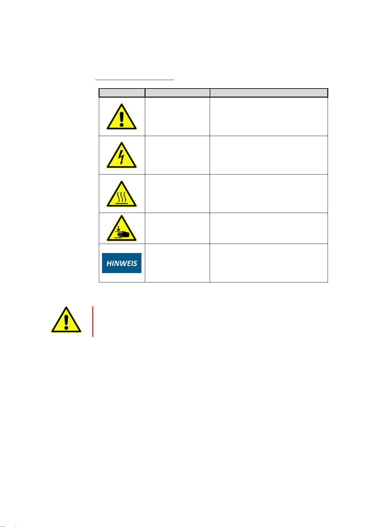
Table 03: Risk classifications
Symbol
Signal word
Meaning
DANGER
This symbol indicates a hazardous situation
presenting an immediate threat of death or
serious injury to persons and life.
DANGER
Danger from electrical voltage.
This symbol indicates danger from
electrical voltage.
DANGER
Danger from hot surfaces.
This symbol indicates risks of burning on
hot surfaces.
DANGER
Danger from hand injuries.
Sections marked with this symbol indicate
hazardous situations presenting danger
from hand crushing.
NOTICE
Refers to a situation that, if not avoided,
could result in damage to the furnace, its
components or objects in its environment.
Warning example:
SIGNAL WORD (Warning)
Cause
Effects
Protective measure(s)
2.5 UNAUTHORIZED PARTS
Before market launch, the furnace was subjected to extensive tests and quality
controls. All components were tested under the highest load levels. Mounting
unauthorized parts affects safety and will exclude all statutory defects liability by
Thermo-Star. Use only original spare parts or spare parts approved by Thermo-Star
when replacing parts.

- 10 -
2.6 GENERAL HAZARDOUS POTENTIAL
This chapter specifies general hazards resulting from the furnace.
2.6.1 THERMAL HAZARD
The furnace operates in cycles. Thermal hazards arise from the furnace door during
operation. Because of its design, the furnace door will not cool down completely.
Please note the safety notes on the furnace.
2.7 ELECTROMAGNETIC COMPATIBILITY
The device does not cause any electromagnetic emission levels or faults in other
devices.

- 11 -
2.8 RESPONSIBILITY OF THE OWNER
The owner and/or user is responsible for ensuring compliance with the following:
Operate the furnace only in accordance with its intended purpose and in
proper condition.
Chapter 2.1 “INTENDED USE”
The functionality of protective devices may not be affected.
Comply with maintenance intervals and eliminate faults immediately.
Eliminate faults yourself only when the required measures
are indicated in this instruction manual.
Thermo-Star or a qualified service company is responsible for implementing
all other measures.
Check that the furnace type plate is complete and legible.
Chapter 4.5 “TYPE PLATE”.
Provide sufficient personal protective equipment and ensure that it is worn.
Chapter 2.3 “PERSONAL PROTECTIVE EQUIPMENT”
Provide the full instruction manual on-site and instruct personnel
accordingly.
First aid: we refer to local and internal corporate provisions when dealing
with accidents. Ensure that sufficient staff are trained in first aid.
The operator must provide suitable fire-fighting equipment and make sure
that the location and handling of fire extinguishers are known. If unsuitable
fire-fighting equipment is used, harmful fumes or hazards from electric shock
may occur.
Danger of injuries or death from electric shock.
Never use water to extinguish electrical equipment. Risk of electric
shocks.
Employ only authorized and adequately qualified personnel.
Chapter 2.2 “QUALIFIED PERSONS”

- 12 -
3TRANSPORT AND STORAGE
This chapter provides information about proper transport and storage of the
furnace.
The furnace and all loose parts and accessories (packed in cardboard or transport tube)
are delivered in a stackable transport packaging made of wood.
Chapter 4.1 “SCOPE OF SUPPLY”
Chapter 4.2.2 “CHARACTERISTICS AND TECHNICAL DATA”
3.1 SAFE TRANSPORT AND STORAGE
During transport and storage, the following hazards must be expected:
WARNING
Read the following safety notes carefully before transport or storage.
Misuse can cause serious injuries.
Make sure that transport and storage personnel are qualified as required.
Chapter 2.2 “QUALIFIED PERSONS”
Transport of the furnace by persons
Physical injuries because of too heavy weight
2 persons are required for transport.
Chapter 3.2 “TRANSPORT”
Chapter 4.2.2 “CHARACTERISTICS AND TECHNICAL DATA”
Transport using truck or industrial truck
Serious crushing, impacts and accidents as a result of inappropriate handling
Wear personal protective equipment.
Chapter 2.3 “PERSONAL PROTECTIVE EQUIPMENT”
Transport the furnace as it was delivered (packed in transport box).
Make sure that the freight is properly secured.
Check that the lifting accessories are suitable and undamaged.
Transport using a loading crane
Serious crushing and impact injuries from swinging or falling loads
Wear personal protective equipment.
Chapter 2.3 “PERSONAL PROTECTIVE EQUIPMENT”
Comply with the maximum load of the crane system and lifting accessories.
Never stand under swinging loads.
Keep other persons out of the danger zone.
Avoid swinging movements.

- 13 -
3.2 TRANSPORT
Please refer to the notes concerning correct transportation of the unit given below.
Red points indicate the respective lifting points.
Table 04: Types of transport
Type of transport
Permitted lifting
points
3.3 STORAGE
Inappropriate storage might damage the furnace.
Make sure you meet or exceed these requirements:
If possible store the furnace in the transport packaging
Avoid dusty or corrosive atmospheres
Temperature: -20°C < TStorage < 60°C
Humidity: < 80%rH, non-condensing
- 14 -
4DESCRIPTION OF THE PRODUCT
This chapter provides information about the scope of supply, characteristics,
accessories and functionality.
4.1 SCOPE OF SUPPLY
When unpacking check that the supplied product is undamaged and complete (see
the table below). There may be differences in the scope of supply as the furnace is
subject to prior sale. Please note the vendor’s delivery notes.
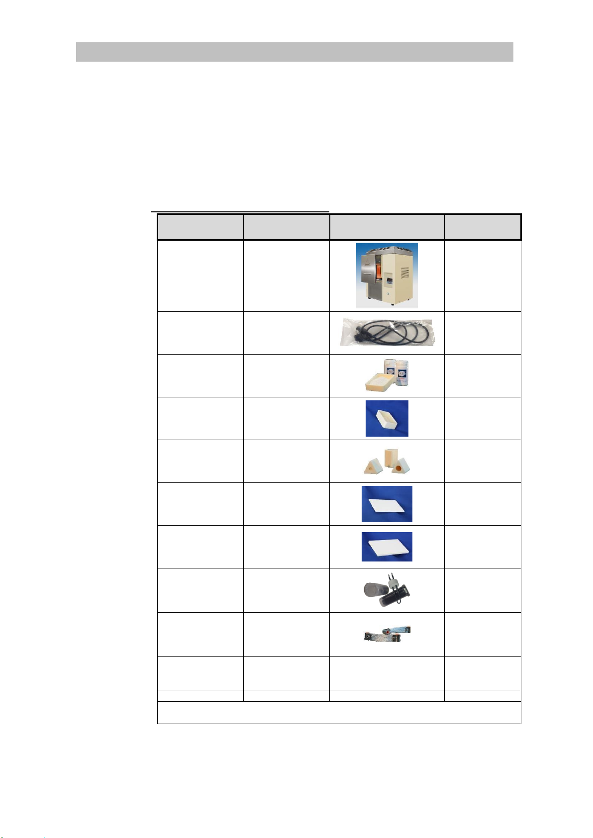
Table 05: Scope of supply of the furnace
Amount /
component
Description
Figure
Packing
1 x furnace
Denta-Star S1
Transport box
1 x mains cable
Mains cable
1.8m, 1.5mm²
IEC 320 <-> C19
Plastic-wrapped
1 x sintering beads
Sintering beads
200g
PET bottle
1 x protective cover
Protective cover
100x70x30mm
Cardboard
4 x spacers
Spacer
h: 20mm
Cardboard
1 x setter
Setter
100x70x2mm
Cardboard
1 x base plate
Base plate
100x70x8mm
Cardboard
3 x heating
elements
Heating element
Transport sleeve
“TwistPack”, if
not pre-
assembled
2 x connecting strip
Connecting strip
EE100 used to
connect the heating
elements
Cardboard, if not
pre-assembled
1 x display
protective foil
Display protective
foil
Self-adhesive
--
Cardboard
1 x documentation
Instruction manual
--
Cardboard
Each sintering aid is suitable for temperatures
T ≤ 1,550°C & Δ T/t ≤ 800°C/h

- 15 -
4.2 PRODUCT CHARACTERISTICS
This chapter describes the main characteristics of the furnace.
4.2.1 SHORT DESCRIPTION OF THE FURNACE
A double fiber-insulated chamber is heated electrically. The required cooling is
carried out using a second wall and ventilators.
The load (sintering aids and ware to be sintered) is placed in the furnace chamber
using a tray in the furnace door. They are subjected to thermal treatment with
normal atmosphere.
An electronic PID control with storage capacity for several temperature-time
profiles is available.
The furnace is operated using an industrial controller positioned on the front of the
furnace. A door switch located below can be used for extended operation.
The main switch and the supply connections for power are located on the back of
the furnace.
4.2.2 CHARACTERISTICS AND TECHNICAL DATA
Table 06: Characteristics and technical data
General
Alumina fiber insulation (Al2O3)
3 molybdenum disilicide heating elements (MoSi2)
Housing made of powder-coated steel sheet and stainless steel
Bolted cover and back wall for easy maintenance
4 rubber feet
Separate cooling air outlet (upwards and to the side, backwards)
Mechanical
Size: 450/390/660 mm (W/D/H)
Weight: 62kg (Net)
Electrical
Voltage: 220-240 V
Supply: ≤ 16 A
Power: ≤ 2,500 W
Temperature: ≤ 1,550°C
- 16 -
4.3 COMPONENTS
The figure below shows the assembly and location of each component. They will
allow the descriptions given in the following chapters to be assigned to the
individual components.
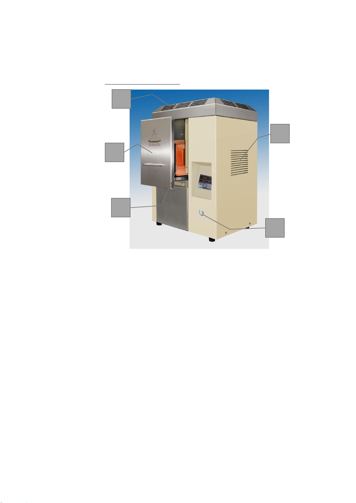
Figure 01: Furnace overview
01
Cooling air outlet, top
04
Setter
02
Cooling air outlet, side
05
Controller
03
Furnace door
06
Door opener
07
Connection to power supply & main switch
(back of the furnace)
01
03
04
02
05
07
06

- 17 -
4.4 FUNCTIONALITY
The furnace is a high-temperature furnace with direct, electrical resistance heating.
Temperature is measured using a thermocouple type S (Pt-PtRh10%; platinum
against platinum-rhodium 10%) placed in the center of the furnace chamber side
wall. The load is assembled on the firing support placed in the furnace door and
the ceramic ware to be sintered is positioned on ceramic sintering aids. The
thermal treatment starts after the furnace has been loaded. Select one of the
stored programs with temperature-time profile to start the process. The
temperature inside the furnace chamber is controlled electronically and modified
in accordance with the selected program. The furnace passes into an automated
cooling phase after ending a process i.e. when the end segment in the active
program has been reached. You can open the furnace at temperatures <300°C to
remove sintered products. The furnace can now be reloaded and is ready for the
next sintering procedure.
4.5 TYPE PLATE
A type plate is attached to the furnace housing. Please find the following
information and keep it at hand for inquiries of any kind:
Figure 02: Example type plate
Serial number
Power supply
Year of construction
4.6 ACCESSORIES
For information about suitable accessories, please see Chapter 1.1 “SERVICE”

- 18 -
5INSTALLATION
This chapter describes how to install the furnace.
Table 07: Requirements for installation
Connections, objects, tools, installation material
Cutter knife
Screwdriver, TX20, PH1
Open-end wrench SW7
Allen key SW3.0
All components Chapter 4.1 “SCOPE OF SUPPLY”
Ambient conditions Chapter 5.2.1 “LOCATION”
5.1 SAFE INSTALLATION
DANGER
Read the following safety notes carefully before installing the furnace.
Misuse can cause serious injuries.
Make sure that installation personnel are qualified as required.
Chapter 2.2 “QUALIFIED PERSONS”
Mechanical hazards
Physical injuries because of too heavy weight
2 persons are required for transport.
Chapter 3.2 “TRANSPORT”
Chapter 4.2.2 “CHARACTERISTICS AND TECHNICAL DATA”
Serious crushing due to falling components such as furnace, gas bottle etc.
Wear personal protective equipment.
Chapter 2.3 “PERSONAL PROTECTIVE EQUIPMENT”
Electrical hazards
Serious injuries or death through contact with live parts
Disconnect power plug before opening the furnace.
Open the furnace only when required for maintenance purposes.
Check electrical installation before installing the furnace.
Never carry out modifications.

- 19 -
5.2 INSTALLING THE FURNACE
Inappropriate positioning might damage the furnace or surrounding parts.
5.2.1 LOCATION
Requirements imposed on the operating location:
Humidity < 85%rH, non-condensing
Ambient temperature > 5°C and < 25°C
Even surfaces
Load-bearing capacity > 100kg
Temperature resistance > 60°C
Air quality of the ambient air should generally correspond to that of the
outside air
Components that are not permitted:
Grinding dusts (independent from material), spray oils, oil vapors, corrosive
gases or vapors and other chemical auxiliary materials i.e. scanner sprays,
separating agents etc.
The distance to the walls, ceilings or other devices should be > 5cm on each
side
The distance to flammable objects should be > 50cm on each side
The distance to hot objects should be > 50cm on each side
(monitor and check to exclude potential interactions)
Socket with grounding contact and separate electric circuit
Fuse preferably with automatic cut-out line protection switch D16A or
fusible cut-out
5.2.2 SETTING UP THE FURNACE
Step 1
Open the transport packaging on each side and remove. The
transport box can be stored and reused.
Screwdriver TX20
Step 2
Remove protective foils and accessories cardboard box and
dispose of them correctly.
Cutter knife
Step 3
Lift furnace and place it on the stand / table
Step 4
Mount the heating elements, if not pre-assembled
Chapter 5.2.3 “MOUNTING HEATING ELEMENTS”
Allen key SW3.0
Open-end wrench SW7
Step 5
Connect to power supply
Chapter 5.2.4 “ELECTRICAL CONNECTION”
Step 6
Connect to network (optional)
Chapter 5.2.5 “NETWORK CONNECTION”
- 20 -
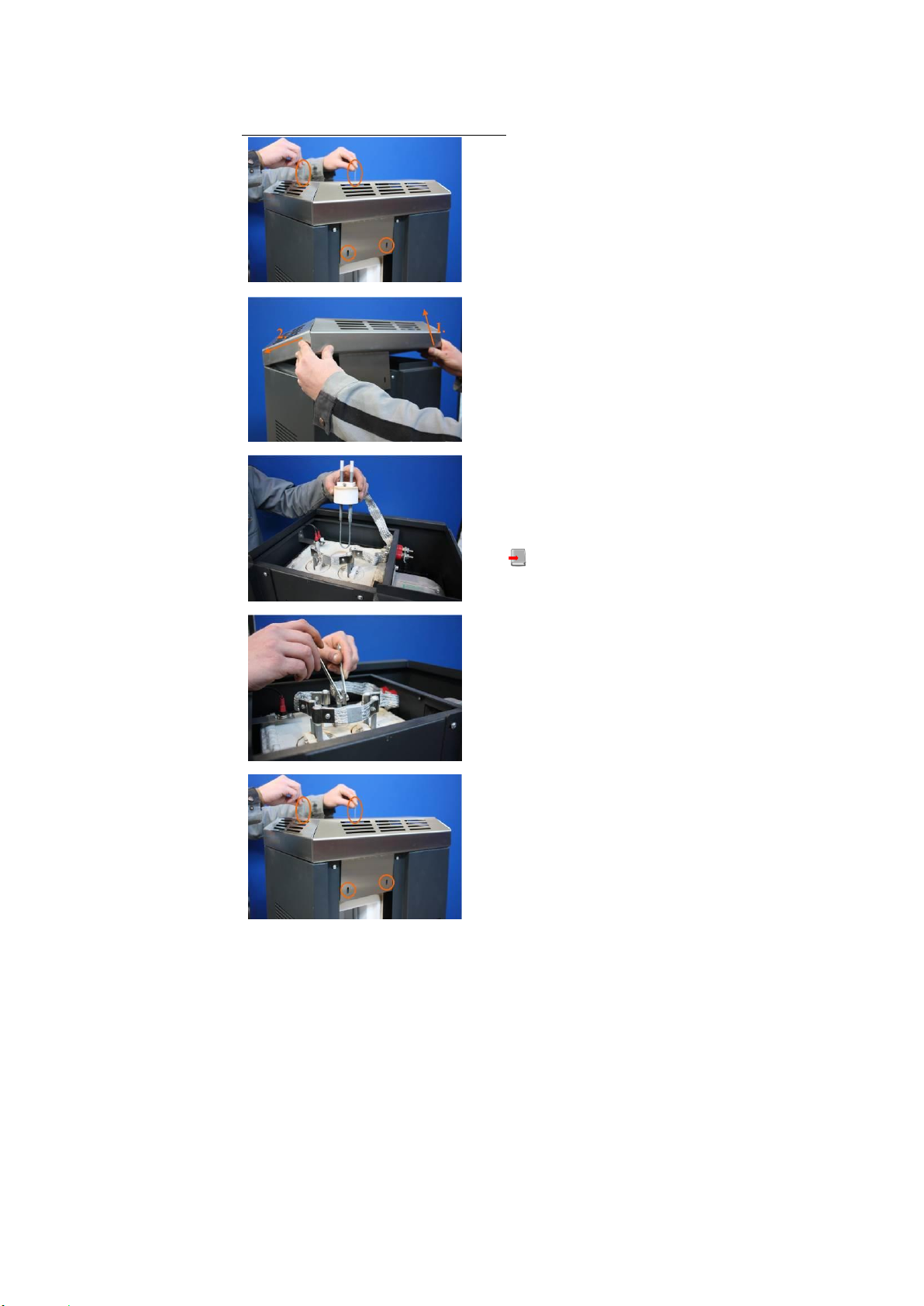
5.2.3 MOUNTING HEATING ELEMENTS
Figure 03: Replacing heating elements
Remove cover screws on both sides
left and right
Lift cover
Remove heating elements from the
transport sleeves and insert
carefully into the holding fixtures
Chapter 4.1 “SCOPE OF SUPPLY” / Table 05
Contact heating elements
Connect pre-installed connecting strips P2E-150
and P2E-200 to the ends of 2 nearest heating
elements. Connect all heating elements using 5
connecting strips E2E-100.
Torque: 3 Nm
Fit cover and insert cover screws at
front and back and screw on tightly
This manual suits for next models
1
Table of contents


