thermofin X-TDH.3-100-22-G-N-D5-BC-04 User manual
Operating and installation instructions for dry cooler translation into English © thermofin GmbH
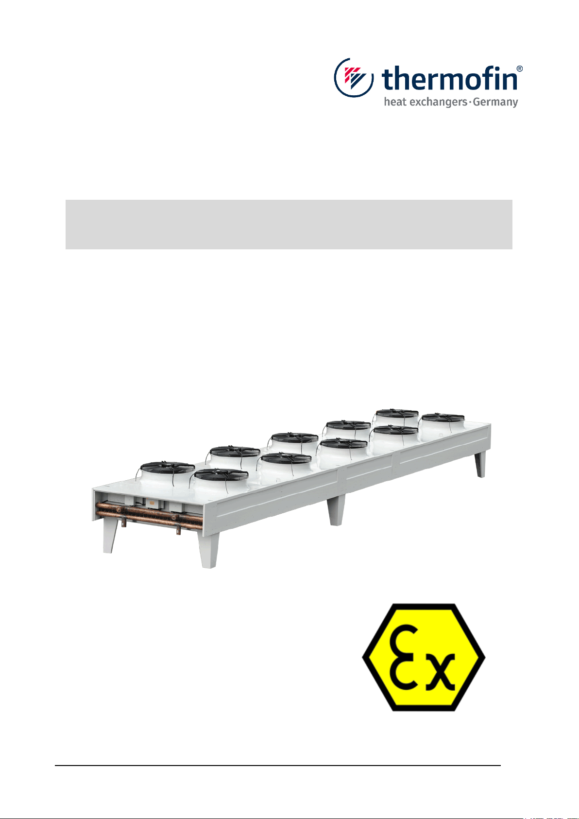
Operating and installation instructions
Dry cooler
X-TDH.3-100-22-G-N-D5-BC-04
Operating and installation instructions 08.02.2021 – Version 1.1
Dry cooler
X-TDH.3-100-22-G-N-D5-BC-04
Page: 2/31
Operating and installation instructions for dry cooler translation into English © thermofin GmbH
Copyright © 2021 by thermofin GmbH, Heinsdorfergrund, Germany.
This publication is protected by copyright.
All rights reserved. All content, photos, text and graphics are protected by copyright. They may not
be copied, changed, reproduced or published in whole or in part without prior written approval.
Original version
This manual has been created in several languages. The German version is a manual in the original
version. All other languages are translations of the original version.
Disclaimer of liability
If problems arise in connection with the installation and/or operation of the device that are not
described in this manual, the operator/installer is obliged to contact thermofin®immediately. Further
installation and/or operation of the device is not permitted until the facts have been fully clarified.
The company thermofin®cannot accept any liability for damage resulting from non-observance of
above-mentioned provisions. Furthermore, thermofin®reserves the right to reject any further
warranty claims on this device that can be traced back hereto.
If you have further questions, please contact the company thermofin GmbH.
Contact details:
Address: thermofin GmbH
Am Windrad 1
08468 Heinsdorfergrund
Germany
Phone: +49 3765 3800-0
Telefax: +49 3765 3800-8038
Email: inf[email protected]
Website: www.thermofin.de

Operating and installation instructions 08.02.2021 – Version 1.1
Dry cooler
X-TDH.3-100-22-G-N-D5-BC-04
Page: 3/31
Operating and installation instructions for dry cooler translation into English © thermofin GmbH
1. Fundamentals .................................................................................5
1.1 Safety instructions and their meaning in this installation manual ............ 5
1.2 Warning signs and their meaning in this installation manual.................... 5
1.3 Prohibition signs and their meaning in this installation manual Range of
application ................................................................................................ 6
1.4 Mandatory signs and their meaning in this installation manual ................ 6
1.5 General preliminary remarks........................................................................ 7
1.6 Validity ........................................................................................................... 8
1.7 Scope of application ..................................................................................... 8
1.8 Standards and directives.............................................................................. 9
1.8.1 Applicable documents................................................................................. 9
2. Technical data ..............................................................................10
2.1 Design data.................................................................................................. 10
2.2 Application and intended use .................................................................... 10
2.3 Material data ................................................................................................ 10
2.4 Notes on noise ............................................................................................ 11
2.5 Device key ................................................................................................... 11
2.6 Data on the type plate ................................................................................. 11
3. Safety ............................................................................................12
3.1 General safety instructions ........................................................................ 12
3.2 Safety instructions on the installation site................................................ 12
3.3 Safety instructions on the unit................................................................... 13
3.4 Safety instructions on the operating supply............................................. 14
3.5 Special conditions for safe use in potentially explosive areas................ 15
4. Transport, storage, positioning, installation ..............................16
4.1 General ........................................................................................................ 16
4.2 Transport ..................................................................................................... 16
4.2.1 Packing .................................................................................................... 17
4.3 Storage ........................................................................................................ 17
4.4 Lifting and positioning of table devices of TDH type ............................... 18
4.4.1 Installation of table devices of TDH type................................................... 19
4.5 Piping connection ....................................................................................... 20
4.5.1 Peculiarities of the dry coolers .................................................................. 20
5. Fans and electrics ........................................................................21
Operating and installation instructions 08.02.2021 – Version 1.1
Dry cooler
X-TDH.3-100-22-G-N-D5-BC-04
Page: 4/31
Operating and installation instructions for dry cooler translation into English © thermofin GmbH
5.1 Connection and installation ....................................................................... 21
5.2 Fans with external rotor motors................................................................. 22
5.3 Electrical switching and control devices................................................... 23
6. Commissioning, normal operation, cleaning, spare parts,
decommissioning, disposal.........................................................24
6.1 Commissioning ........................................................................................... 24
6.1.1 Return to service after a longer period of standstill ................................... 24
6.2 Normal operation ........................................................................................ 25
6.3 Cleaning....................................................................................................... 25
6.3.1 Cleaning of the fins................................................................................... 25
6.3.2 Cleaning of the housing ............................................................................ 26
6.4 Spare parts .................................................................................................. 26
6.5 Decommissioning ....................................................................................... 26
6.6 Disposal....................................................................................................... 27
7. Inspection and maintenance .......................................................28
7.1 Maintenance plan (production) .................................................................. 29
8. Troubleshooting ...........................................................................31
Operating and installation instructions 08.02.2021 – Version 1.1
Dry cooler
X-TDH.3-100-22-G-N-D5-BC-04
Page: 5/31
Operating and installation instructions for dry cooler translation into English © thermofin GmbH
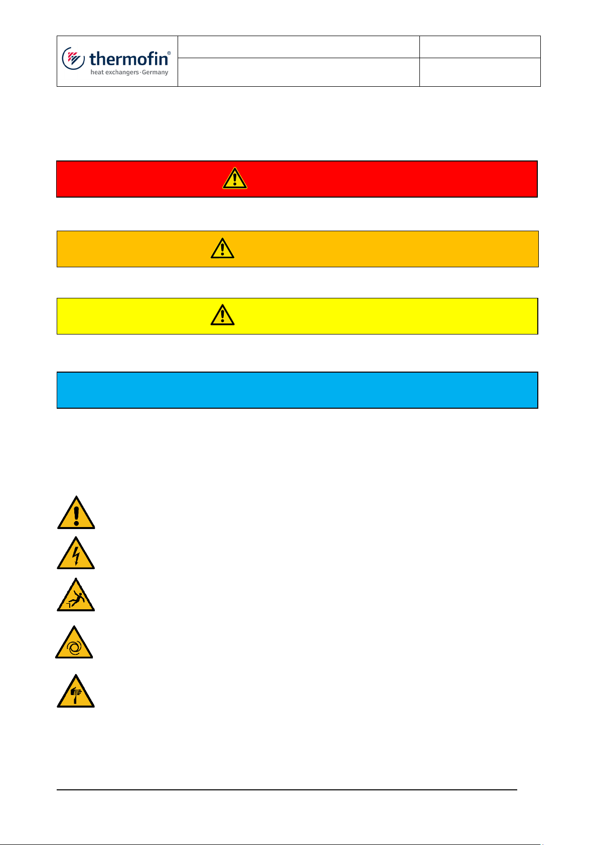
WARNING
CAUTION
NOTE
1. FUNDAMENTALS
1.1 Safety instructions and their meaning in this installation manual
Dangerous situation which can certainly result in serious injury or death if not avoided.
Dangerous situation that could result in serious injury or death if not avoided.
Dangerous situation that could result in a minor to moderate injury if not avoided.
Note of possible property damage
1.2 Warning signs and their meaning in this installation manual
The warning signs used are based on the DIN EN ISO 7010 standard.
W001 General warning sign
W012 Warning of electrical voltage: Risk of electric shock when touching live parts
W008 Warning of falling hazard: Do not climb onto the device unsecured
W018 Warning of automatic start-up: Automatic start-up of fans can lead to serious
injuries in the finger and hand area
W022 Warning of cut injuries: Sharp edges can cause cuts
DANGER
Operating and installation instructions 08.02.2021 – Version 1.1
Dry cooler
X-TDH.3-100-22-G-N-D5-BC-04
Page: 6/31
Operating and installation instructions for dry cooler translation into English © thermofin GmbH
1.3 Prohibition signs and their meaning in this installation manual Range of
application
The prohibition signs used are based on the DIN EN ISO 7010 standard.
P003 No open flame; fire, open source of ignition and smoking prohibited: No ignition
source may be introduced or brought into the vicinity and no ignition source may arise.
P002 Smoking prohibited
P024 Entering the area prohibited
1.4 Mandatory signs and their meaning in this installation manual
The prohibition signs used are based on the DIN EN ISO 7010
M009 Use hand protection: The hand protection used must be suitable for the equipment
used and for the prevailing operating temperatures.
M017 Use respiratory protection: The respiratory protective device used must be suitable
for the equipment used.
M013 Use face protection: Use face protection hood.
M010 Use protective clothing: The protective clothing must be suitable for the equipment
used and for the prevailing operating temperatures.
M021 Disconnect before maintenance or repair: Before starting work, switch off the
electrical power supply and secure it against being switched on again. Check that there is
no voltage.

Operating and installation instructions 08.02.2021 – Version 1.1
Dry cooler
X-TDH.3-100-22-G-N-D5-BC-04
Page: 7/31
Operating and installation instructions for dry cooler translation into English © thermofin GmbH
NOTE
1.5 General preliminary remarks
This manual includes the installation manual in accordance with the Machinery Directive 2006/42/EC,
the operating manual in accordance with the Pressure Equipment Directive 2014/68/EU as well as
the operating manual in accordance with ATEX Directive 2014/34/EU.
Operating and installation manuals serve the purpose of avoiding possible hazards to people and
the environment that may arise from a device and work in connection with this device, in particular
during transport, installation, commissioning and operation of the device. For this reason it is
necessary to carefully read and observe all points in this manual.
A claim to warranty does not exist in the case of faults and damage that can be attributed
to the fact that the specifications of this installation manual were not adhered to or in the
case of complaints that arose from the replacement of parts with non-original parts or from
conversions or changes not expressly authorized by the manufacturer or changes to the
operating parameters or functionality of the device.
Please keep this manual in such a way that this is always accessible to all persons who
have anything to do with this device. Make sure that this manual is read and understood by
everyone who works with this device.
This manual is available on our website in the download area under the Service section and
can be downloaded as a PDF document.
Direct link: https://www.thermofin.de/en/technical-documentation.php
Or scan this QR code with your smartphone:

Operating and installation instructions 08.02.2021 – Version 1.1
Dry cooler
X-TDH.3-100-22-G-N-D5-BC-04
Page: 8/31
Operating and installation instructions for dry cooler translation into English © thermofin GmbH
WARNING
1.6 Validity
This installation manual refers to the device: X-TDH.3-100-22-G-N-D5-BC-04
according to the final and supplied device data sheet:
−Unit design as a table device
−Heat exchanger made of stainless-steel pipes V4A with fins made of aluminium-magnesium
−Housing made of V4A, powder-coated
The technical data can be seen from the order-specific unit data sheet and the type plate.
For fans and electrical equipment components, the information on their identification plates
and their operating manual apply primarily.
1.7 Scope of application
The dry cooler is used in potentially explosive areas in cooling circuits to transfer heat to the ambient
air. It is explosion-proof equipment approved for use in hazardous areas of Zone 2 for gas group IIB
(IIA) and T3 (max. 200°C).
Intended use includes observing this operating manual and the other applicable documents, e.g. the
technical documentation of the certified electrical devices (motor, terminal box).
The device is intended for installation outdoors.
All other uses of the table cooler are not permitted.
The maximum pressure indicated on the type plate must neither be exceeded during
operation nor during transport or storage or standstill!

Operating and installation instructions 08.02.2021 – Version 1.1
Dry cooler
X-TDH.3-100-22-G-N-D5-BC-04
Page: 9/31
Operating and installation instructions for dry cooler translation into English © thermofin GmbH
1.8 Standards and directives
The manufacturer certifies the compliance with the standards according to the order-related
declaration of incorporation and/or declaration of conformity included in the documents of the
devices.
In addition, the content of the relevant regulations and national provisions that apply at the installation
site must be observed. These include, among other things, regulations on the expertise of the
operating personnel, operational safety, emission protection, explosion protection and maintenance
and repair.
A suitably qualified specialist is required for the activities described in this operating manual. This
applies above all to work in the following areas:
−Product selection, project planning and modification
−Assembly / disassembly of the device
−Installation
−Commissioning
−Overhaul, repairs, cleaning
Skilled workers who carry out these activities must have a level of knowledge that meets the following
requirements:
−all national standards and regulations
Additional knowledge is required for activities in potentially explosive areas!
thermofin recommends a level of knowledge that is described in the following standards:
−EN IEC 60079-14 (project planning, selection and construction of electrical systems)
−EN IEC 60079-17 (testing and maintenance of electrical systems)
−EN IEC 60079-19 (equipment repair, overhaul and regeneration)
Local and national peculiarities and/or regulations must be taken into account.
1.8.1 Applicable documents
−this manual which is the part of the operating manual for the entire system,
−which is provided by the installer of the system
−order-related designs, data sheets
−order-related or device-specific drawings
−order-related or device-specific circuit diagrams
−connection diagrams in the terminal boxes of the electrical components
−identification labels on the device
−EU declaration(s) of conformity for certified ATEX devices
−Operating manuals for certified ATEX devices

Operating and installation instructions 08.02.2021 – Version 1.1
Dry cooler
X-TDH.3-100-22-G-N-D5-BC-04
Page: 10/31
Operating and installation instructions for dry cooler translation into English © thermofin GmbH
WARNING
2. TECHNICAL DATA
2.1 Design data
The design data of the unit are shown in the respective order documents and/or the unit data sheet.
It can also be requested from factory by indicating the project or serial number (see type plate). The
device consists of non-electrical components and purchased electrical devices certified according to
ATEX.
Only original accessories and spare parts from thermofin company may be used.
Changes to the design conditions, environmental conditions, operating parameters or operating fluids
must be authorized in writing by the manufacturer, otherwise the warranty claim expires.
2.2 Application and intended use
The unit as incomplete machine according to Machinery Directive 2006/42/EC is intended for the
installation in cooling systems. In principle, the device is suitable for installation outdoors.
Despite meeting the requirements of intended use and handling the unit properly, residual
risks cannot be completely prevented.
The unit may only be put into operation when the conformity of the entire system has been
established!
The unit may only be used in places where the materials applied are not affected by the
surrounding atmosphere or the medium flowing inside.
Any case of application differing from the one described above requires consultation with
the manufacturer.
The manufacturer does not assume liability for any damages resulting from the non-
compliance with these provisions.
2.3 Material data
Tubes: Stainless steel 1.4404, welded
Fins: Aluminium-magnesium, bright
Housing: Stainless steel 1.4404, powder-coated, UV and corrosion resistant according to
corrosivity category C5-M according to DIN EN ISO 12944-2

Operating and installation instructions 08.02.2021 – Version 1.1
Dry cooler
X-TDH.3-100-22-G-N-D5-BC-04
Page: 11/31
Operating and installation instructions for dry cooler translation into English © thermofin GmbH
2.4 Notes on noise
The specified noise pressure was calculated in accordance with DIN EN 13487 and denotes the
mean value of the noise pressure on the entire envelope surface at the specified distance.
2.5 Device key
2.6 Data on the type plate
model description according to the device key
(see 2.5 device key)
ATEX marking
article number of the manufacturer
project or serial number
month / year of manufacture
tube volume of the heat exchanger
empty weight of the device
device no.
maximum working pressure PS
test overpressure PT
pressure test medium of the heat exchanger
permissible temperature range of the fan
allowed temperature range of the medium TS
electrical connection values
Operating and installation instructions 08.02.2021 – Version 1.1
Dry cooler
X-TDH.3-100-22-G-N-D5-BC-04
Page: 12/31
Operating and installation instructions for dry cooler translation into English © thermofin GmbH
3. SAFETY
3.1 General safety instructions
The unit is state-of-the-art and reliable in operation. The unit may only be used in accordance with
the specifications in the catalogue and the data given on the type plate. The unit may only be
installed, commissioned and maintained by competent personnel. During installation, the conditions
in accordance with all applicable and valid standards and regulations must be observed. The
company installing the system has to ensure the observance of all pressure and temperature limit
values given on the type plate.
Compliance with the instructions of this operating manual does not release the plant
operator from the obligation to install an appropriate warning system indicating each kind of
malfunction immediately. In addition, emergency measures must be planned and prepared
in order to prevent consequential damages in case of malfunctions.
3.2 Safety instructions on the installation site
Pipes and fittings must be protected against misuse. Emergency facilities, such as lighting, venting,
escape routes and the marking of which must be provided.
The unit must be lockable in case of leakage. Devices which are used for the discharge of released
refrigerants must be operable from a safe location.
No smoking at the installation site. Open fire is prohibited.
There must be sufficient free space around the unit in order to prevent dangers to the unit and its
connections and to ensure smooth execution of maintenance and repair work on the unit as well as
on all fittings and components.
The unit must be connected to the supporting structure with all fastening points evenly, without
twisting or bending, and must be fastened to the supporting structure using suitable means. It must
be ensured that the subsoil and supporting structure can withstand the unit load over the long term
and that there are no signs of distortion or settlement.
To avoid the risk of ignition, there must be no rust or rust film on the device, on the pipes or
in the vicinity of the device.

Operating and installation instructions 08.02.2021 – Version 1.1
Dry cooler
X-TDH.3-100-22-G-N-D5-BC-04
Page: 13/31
Operating and installation instructions for dry cooler translation into English © thermofin GmbH
WARNING
3.3 Safety instructions on the unit
Before performing installation, repair and maintenance works, the power supply must be
interrupted at all circuits. An unauthorized and / or unintentional (automatic) restart must be
prevented. Zero potential must be checked and - if applicable - ensured by the means of
earthing or short circuiting. Adjacent energized parts need to be covered.
Do not touch the fin edges – risk of cuts!
Entering the device is only permitted with suitable falling protection!
It is forbidden to stick objects through the fan guard or into the circle of the fan blades.
Before performing welding work, the unit must be emptied!
In the event that refrigerants escape, use your personal protective equipment. Avoid any
contact with the refrigerant. In case of eye contact, seek medical advice immediately!
Do not use any connections or pipes to climb. Do not step on fans!
If the temperature difference between the ambient temperature and the medium inlet temperature
exceeds 70K, the max. permitted temperature slew rate must be observed:
Start temperature
Temperature increase
max.
T_ambient < +10°C
1.5 K/min
T_ambient ≥ +10°C
3.0 K/min

Operating and installation instructions 08.02.2021 – Version 1.1
Dry cooler
X-TDH.3-100-22-G-N-D5-BC-04
Page: 14/31
Operating and installation instructions for dry cooler translation into English © thermofin GmbH
WARNING
3.4 Safety instructions on the operating supply
The unit was designed for operation with an ethylene glycol-water mixture.
Ethylene glycol is a colourless, slightly viscous, slightly volatile and hygroscopic liquid that can be
mixed with water. It has a sweetish smell and taste. Ethylene glycol vapours are heavier than air and
thus they may reach lower spaces. At ground level, the concentration may increase in quiescent air.
In case of high concentrations, there is a risk of suffocation due to the reduced oxygen percentage
in the breathable air.
The operating supplies must be prevented from escaping.
After skin contact, ethylene glycol causes a slight irritation with the risk of skin resorption.
Eye contact causes mucous membrane irritations. After being swallowed, the substance
produces states of agitation with disorders of the central nervous system as well as fatigue,
loss of consciousness, coordination disorders and kidney damage.
Keep ethylene glycol away from ignition sources, do not smoke!
Avoid the contact of ethylene glycol with open flames or hot surfaces. Be careful when
executing soldering and welding works!
During troubleshooting, avoid eye and skin contact as well as contact with clothes.
Use your personal protective equipment. Take off soiled or soaked clothes
immediately!
Further and more detailed information and direction for use and first aid as well as provisions resulting
therefrom are to be found in the corresponding safety data sheet.
Operating and installation instructions 08.02.2021 – Version 1.1
Dry cooler
X-TDH.3-100-22-G-N-D5-BC-04
Page: 15/31
Operating and installation instructions for dry cooler translation into English © thermofin GmbH
WARNING
3.5 Special conditions for safe use in potentially explosive areas
Carry out installation strictly in accordance with the operating manual and taking into account the
national safety and accident prevention regulations (e.g., IEC/EN 60079-14).
Observe the applicable national regulations in the country of use, e.g., EN IEC 60079-14, EN IEC
60079-17, EN IEC 60079-19.
A suitably qualified specialist is required for the activities described in this operating manual. This
applies above all to work in the following areas
−Product selection, project planning and modification
−Assembly/disassembly of the device
−Installation
−Commissioning
−Overhaul, repairs, cleaning
Skilled workers who carry out these activities must have a level of knowledge that meets the following
requirements:
- All national standards and regulations
Further notes:
−Ensure and check equipotential bonding
−Maintain the ambient temperature range
−Adhere to the special conditions of the already certified units
−Do not apply paint (electrostatics)
−Observe the cleaning instructions according to Section 6.3
−Do not apply warning stickers
−Observe the max. process temperature/refrigerant temperatures!
To avoid the risk of ignition, there must be no rust or rust film on the device, on the pipes or
in the vicinity of the device.

Operating and installation instructions 08.02.2021 – Version 1.1
Dry cooler
X-TDH.3-100-22-G-N-D5-BC-04
Page: 16/31
Operating and installation instructions for dry cooler translation into English © thermofin GmbH
NOTE
4. TRANSPORT, STORAGE, POSITIONING, INSTALLATION
4.1 General
The device may only be installed, integrated into an overall system, operated and repaired by
specialist companies with appropriately competent personnel.
During production and before delivery, each unit is subjected to comprehensive quality
testing. The unit is provided in good order and condition. With delivery and before assembly,
the unit must be checked for damages (damages in transit).
4.2 Transport
During transport, the unit must be handled with special care. In particular, always place the
unit very carefully on the ground!
If indications on transport or storage are attached to the unit or the packaging, they must be
absolutely observed!
Attachment points: Attach device here
No attachment point: DO NOT attach here!
DO NOT use a forklift or pallet truck on this side!
Areas or components marked in this way must NOT be entered!
Continuous mechanical loads due to bumps and potholes on the roadway can cause
damages in transit.
Transportations by ship can cause damages in transit due to vibrations.
In case of critical transport routes (countries with bad streets or seaway) the mounting parts
which could be set into vibration, especially fans, collectors, foot stands, must be
disassembled and secured separately.
Units must be firmly fixed on the transport vehicle and protected against vibrations, punches
and slipping!
Operating and installation instructions 08.02.2021 – Version 1.1
Dry cooler
X-TDH.3-100-22-G-N-D5-BC-04
Page: 17/31
Operating and installation instructions for dry cooler translation into English © thermofin GmbH
4.2.1 Packing
Decisive factors for packing are the route of transport, the size of the equipment and the regulations
applicable in the country of importation.
If not otherwise expressly agreed, the delivery is effected ex works in standard transport
packaging at the discretion of thermofin®. According to contractual agreement, design and
packaging are sufficient for the transport to the contractual agreed place of transfer of risk.
Possible packaging designs are described below.
The purchaser is responsible for a possible further transport and the respective packaging,
unless otherwise expressly agreed.
In case of a packaging by external companies ordered by the purchaser or the customer,
thermofin® cannot give any warranty for the design of the packaging and possible resulting
transport damages. A safe design of the packaging should be agreed with thermofin®.
The pallets, crates and export boxes used for thermofin® units meet the requirements of the HPE
and VDM standards (HPE – German Federal Association for Wooden Packages, Pallets and
Export Packaging; VDM – Association of the German Furniture Industries). If required, they can be
tailored to the standards of ISPM 15.
thermofin® transport packages are made of environmental friendly materials and they are suitable
for recycling.
According to the German regulation on packaging, we are prepared to take back our packages if
they are returned to us, delivered free to our location in Heinsdorfergrund.
thermofin® units are usually delivered fully assembled. In the event that a unit is delivered
disassembled – due to transportation or other reasons – it must be assembled on site according to
the order-specific drawings enclosed.
In the event that a unit is delivered disassembled – due to transportation or other reasons – it must
be assembled on site according to the order-specific drawings enclosed.
Loading on road vehicles is performed in accordance with the VDI guideline 2700 “Securing of
loads on road vehicles”.
In case of groupage traffic and reloading, the responsibility lies with the forwarder.
4.3 Storage
If the units must be stored, the following points must be observed:
Store the units on a proper, dry place protected against environmental influences! Protect
the fans against rain and condensation humidity (cold-warm)!
Store the units in an uprising, torsion-free and deflection-free manner!
Do not open the junctions; maintain the delivery pressure of the unit!
Operating and installation instructions 08.02.2021 – Version 1.1
Dry cooler
X-TDH.3-100-22-G-N-D5-BC-04
Page: 18/31
Operating and installation instructions for dry cooler translation into English © thermofin GmbH
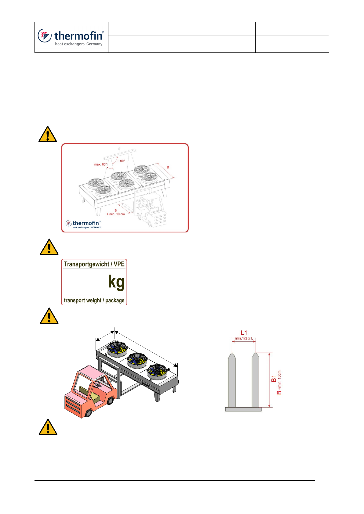
4.4 Lifting and positioning of table devices of TDH type
When positioning the equipment, the lifting instructions attached to the device must be observed.
Furthermore, the appropriate lifting accessories must be used. The sheet metal components of the
housings may not be deformed by the belts. If it is not possible to ensure sufficient rope length (angle
to the perpendicular of max. 30°), a traverse must be used. The lifting accessories may only be
attached to the suspension points intended for this purpose.
Never use pipes or attachment parts for lifting!
The factory-provided transport weight (empty weight of the unit + transport packaging) can
be found on the corresponding label fixed to the transport packaging.
In case of using floor-borne vehicles a sufficient length of the forks must be ensured.
Please pay attention to the position of the centre of gravity as well as to the signs!
Lifting the front side with a forklift or lifting with forks that are too short will destroy the heat
exchanger and will void the warranty.
If further indications on transport or storage are attached to the unit or the packaging, they must be
absolutely observed
B
L
Operating and installation instructions 08.02.2021 – Version 1.1
Dry cooler
X-TDH.3-100-22-G-N-D5-BC-04
Page: 19/31
Operating and installation instructions for dry cooler translation into English © thermofin GmbH
4.4.1 Installation of table devices of TDH type
The suitability and the load bearing capacity of the foundations, brackets, machine frames etc. –
provided by the customer – are not the responsibility of the equipment manufacturer. When
calculating the bearing load, in addition to the empty weight of the unit, the weight of the pipe content
and possible additional weights such as snow, moisture or dirt must be taken into account.
It must be ensured that the subsoil and supporting structure can withstand the unit load over
the long term and that there are no signs of distortion or settlement.
The device must sit evenly on all support points without twisting or bending and must be attached to
the supporting structure using appropriate fasteners. The mounting holes on the device base are to
be used for this. Noise-decoupling rubber-metal feet optionally included in the scope of supply are
designed specifically for the unit and are to be mounted under the unit feet on site. Anti-vibration
metal feet are only suitable for absorbing vertical pressing forces, any pushing or pulling force in the
transverse direction must be avoided and in extreme cases can lead to the destruction of the foot.
Installation in standing water (depressions, glycol sumps ...) can lead to rust formation on
the rubber or unit base and endanger the stability of the unit.
After installation and before commissioning, all packaging parts as well as means for transport
protection must be removed.
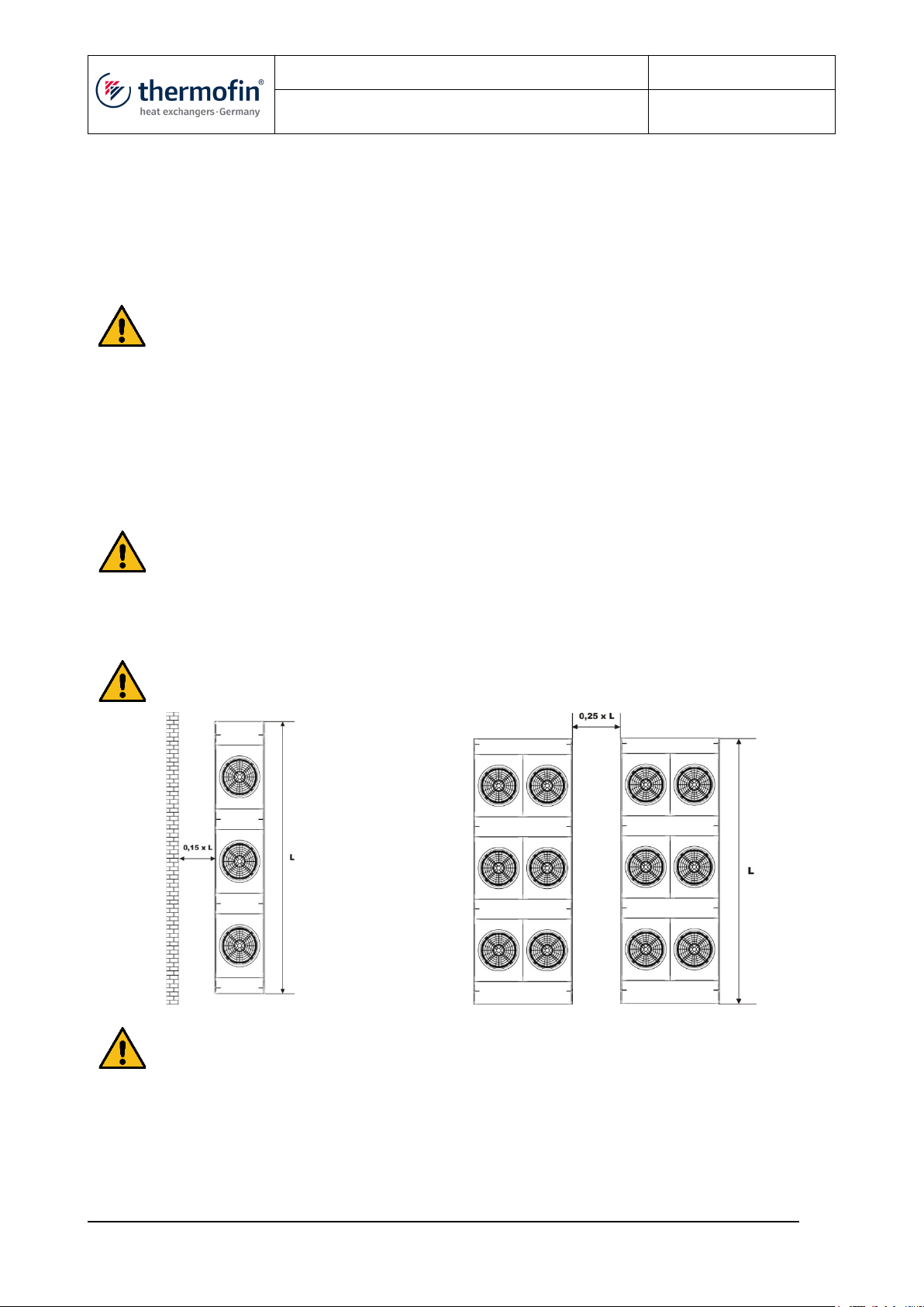
Make sure there is sufficient clearance to walls, facings and the like. The air flow must not
be obstructed in any way. The specified dimensions are minimum distances!
Deviating installation conditions must be clarified with the manufacturer. Special measures
may have to be taken, e.g. extended feet or air ducts.

Operating and installation instructions 08.02.2021 – Version 1.1
Dry cooler
X-TDH.3-100-22-G-N-D5-BC-04
Page: 20/31
Operating and installation instructions for dry cooler translation into English © thermofin GmbH
NOTE
NOTE
4.5 Piping connection
Soldered or welded units or units closed with counter flanges are delivered with an overpressure of
approx. 1 bar (cleaned and dried air) (according to the regulation for the transportation of hazardous
material ADR 1.1.3.2 c).
Before opening the unit, it must be verified that the overpressure is present.
A depressurized unit indicates a leakage (Damage in transit! Leak test!).
In case of depressurized units, the manufacturer must be consulted immediately.
Before assembly, the transport pressure must be released and the closing caps must be removed.
Pipe connections must be designed in such a way that any force, stress and vibration effects
on the unit are prevented.
In access lines, a fixed point must be provided at a distance of max. 500mm from the unit connection.
Follow inlet and outlet according to the marking.
Flange seals on dry coolers must not be greased, sealing surfaces must be clean, bright
and even.
4.5.1 Peculiarities of the dry coolers
Since a complete emptying of the unit cannot be guaranteed with dry coolers, the system must be
rinsed with antifreeze after the leak test with water if there is a risk of frost. The rinsing takes place
by means of a pump which is connected to the drainage port of the unit via a hose connection. Before
this, the unit must be shut off from the heat transfer medium circuit. The antifreeze, mixed with water,
escapes through the venting nozzle and is fed into a collecting container from which the pump sucks
in again. In order to ensure sufficient mixing, at least a 10-fold circulation is required. The frost
protection achieved can be determined from the mixture in the collecting container.
Table of contents


