EMX HAWK 2 User manual

EMX Industries, Inc. Tech support: 216-518-9889 1/3
HAWK 2™
Overhead Microwave Motion Sensor
Instruction Manual
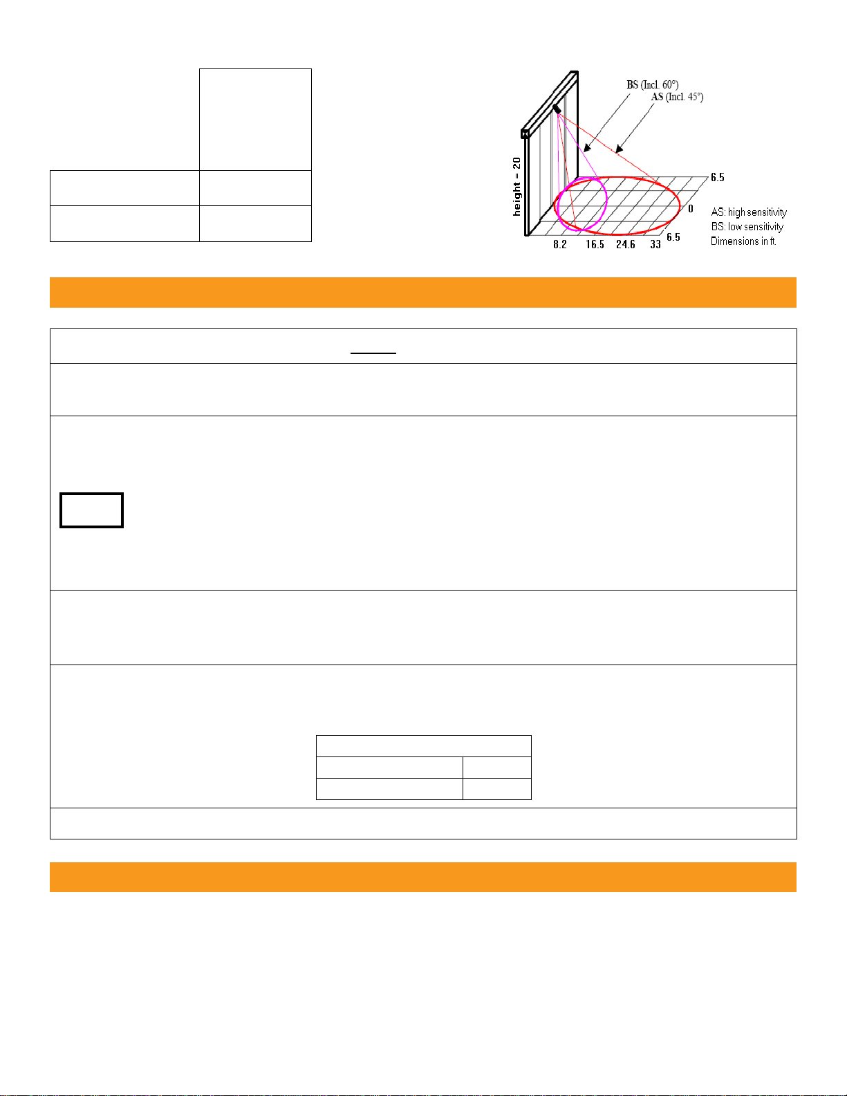
The HAWK 2 is a K-band microwave sensor. It detects the movement of people and vehicles in the
monitored area. The HAWK 2 is used for operating automatic doors and industrial gates. It has a versatile
mechanical orientation system for accurate positioning to the required coverage area making it easy
to install. The detection sensitivity and direction of movement (toward, away or both) are programmed by
DIP switch settings.
Cautions and Warnings
This product is an accessory or part of a system. Install the HAWK 2 according to
instructions from the gate or door operator manufacturer. Comply with all applicable
codes and safety regulations.
Specifications
Ordering Information
•HAWK 2 Overhead Microwave Motion Sensor
Operating Frequency
24.150 GHz
Detection Range
3-33 ft (1-10 m) (adjustable)
Vertical Directionality
0-60°
Horizontal Directionality
+/- 45°
Mounting Height
10-20 ft (3-6 m)
Power
12-24 VDC/AC
Current Draw
40 mA (relay activated)
Relay Output
Form C (SPDT)
Relay Hold Time
1-6 seconds (adjustable)
Relay Contact Rating
1 A @ 24 VDC/AC
Operating Temperature
-4° to 122°F (-20° to 50°C)
Dimensions (L x W x H)
6.3” (160 mm) x 3.8” (95 mm) x 4.4” (110 mm)
Connection
6.5 ft (2 m) cable
Housing Material
ABS plastic
Weight
1.0 lbs (450 g)
Environmental Rating
IP66
TM

Wiring
Wire Color
Description
Red
12-24 VDC/AC
Black
12-24 VDC/AC
Green
Relay –COM (common contact)
Brown or Yellow
Relay –NO (normally open contact)
Blue
Relay –NC (normally closed contact)
Diagram & Settings
1. Output Period Setting
The output period setting allows for
adjustment of the output duration
contact after motion is no longer
detected. The output period can be set
to 1 to 6 seconds. Rotating the setting
clockwise increases the output period.
Rotating the setting counterclockwise
decreases the output period.
2. Range Setting
After DIP switch 4 is set to a high or low
sensitivity, the range setting can be
used to fine tune the detection area.
3. DIP Switches
Detection Mode
DIP Switch 1
In Bi-Directional mode the relay is activated when motion occurs
both leaving and approaching the sensor, DIP switch 2 is ignored.
In Mono-Directional mode the relay is activated only when
motion occurs in the direction specified by DIP switch 2.
Bi-Directional
on
Mono-Directional
off
Mono-Directional
Mode
DIP Switch 2
DIP switch 2 determines which direction of motion activates the
relay when in Mono-Directional mode.
Detect Leaving
on
Detect Approaching
off
Configures the relay contacts position (NO/NC) when in detect
and no-detect states.
Normal Operation
Positive Safety
Relay Operation
DIP Switch 3
Normal Operation
on
Positive Safety
off
Sensitivity
Adjustment
DIP Switch 4
DIP switch 4
determines the area of
detection. The primary
purpose of the
sensitivity setting is to
allow the installer the
ability to control the
area of detection.
Low
on
High
off
Installation
1. Wire the HAWK 2 according to the Wiring section and according to operator instructions.
2. Remove the rubber plug from the back of the sensor and configure the DIP switches,
output period, and range as desired.
3. Mount the HAWK 2 at a height between 10-20 feet. Use the provided mounting template to drill
appropriately distanced holes on the mounting surface.
Do not install the Hawk 2:
•Facing the moving parts of a door
•Facing and closer than 6.5 feet to fluorescent lights
•Facing an area where rain could provoke water fluxes
4. Remove the lower cover of the mounting base and loosen the screw that locks the sensor
orientation using a size 3 allen key. Aim the HAWK 2 towards the desired detection area and lock
the screw in that position. Replace the lower cover of the mounting base and rubber plug.
5. Test the setup by causing motion in the detection zone and adjust the Range Setting until the
desired detection is achieved. The red LED will be on when the motion in the configured
direction(s) is detected.
Red LED
No Detection
Off
Detection
On
6. Cease movement and the red LED will turn off once the output period has passed.
Warranty
EMX Industries, Inc. products have a warranty against defects in materials and workmanship for a period
of two years from date of sale to our customer.
TIP:
Other EMX Accessories manuals


