TeraBee TeraRanger Evo Series User manual

User Manual for
TeraRanger Evo Mini
Technical support: [email protected]
Sales and commercial inquiries: [email protected]

Table of contents
1. Introduction 4
1.1. About Terabee 4
1.2. Symbols explanation 4
1.3. Technical Specifications 5
1.3.1. Performance Matrix 6
1.3.2 Communication interfaces 6
1.4. Pixel modes introduction 7
2. Mechanical integration 8
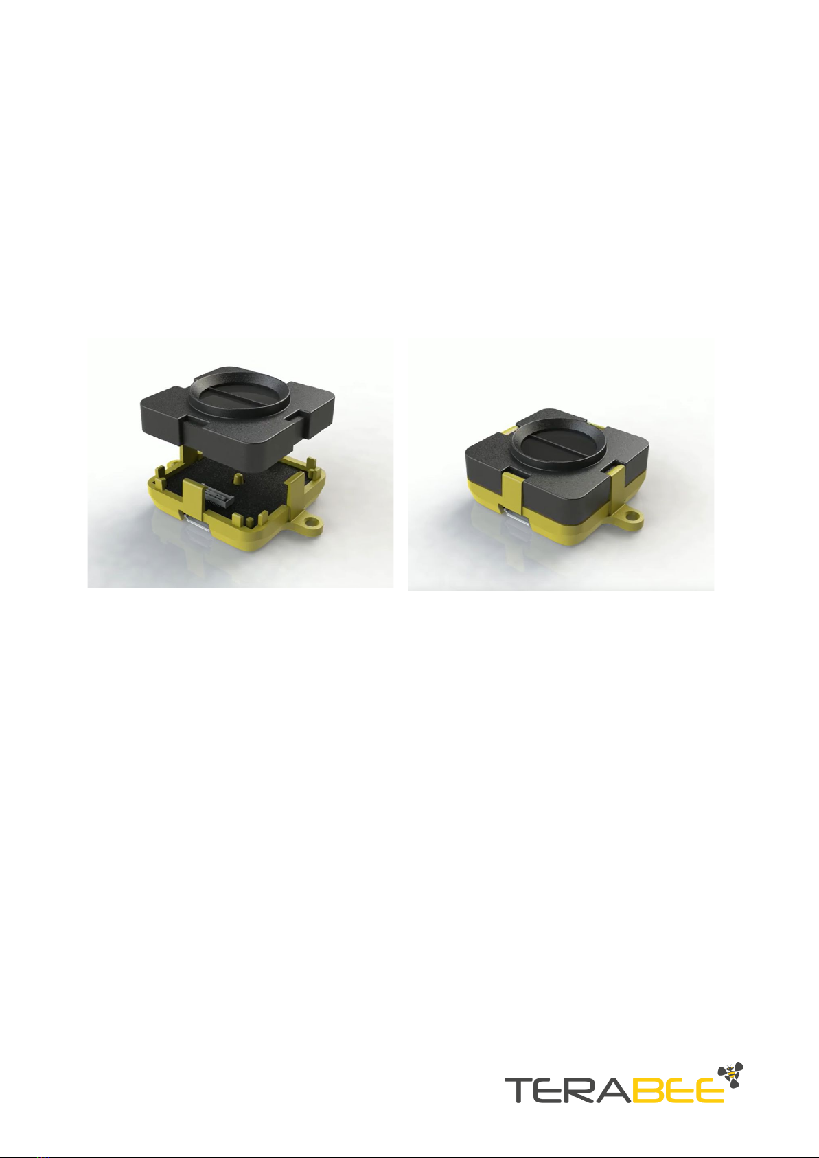
2.1. Modular design (clip-on, clip-off) 8
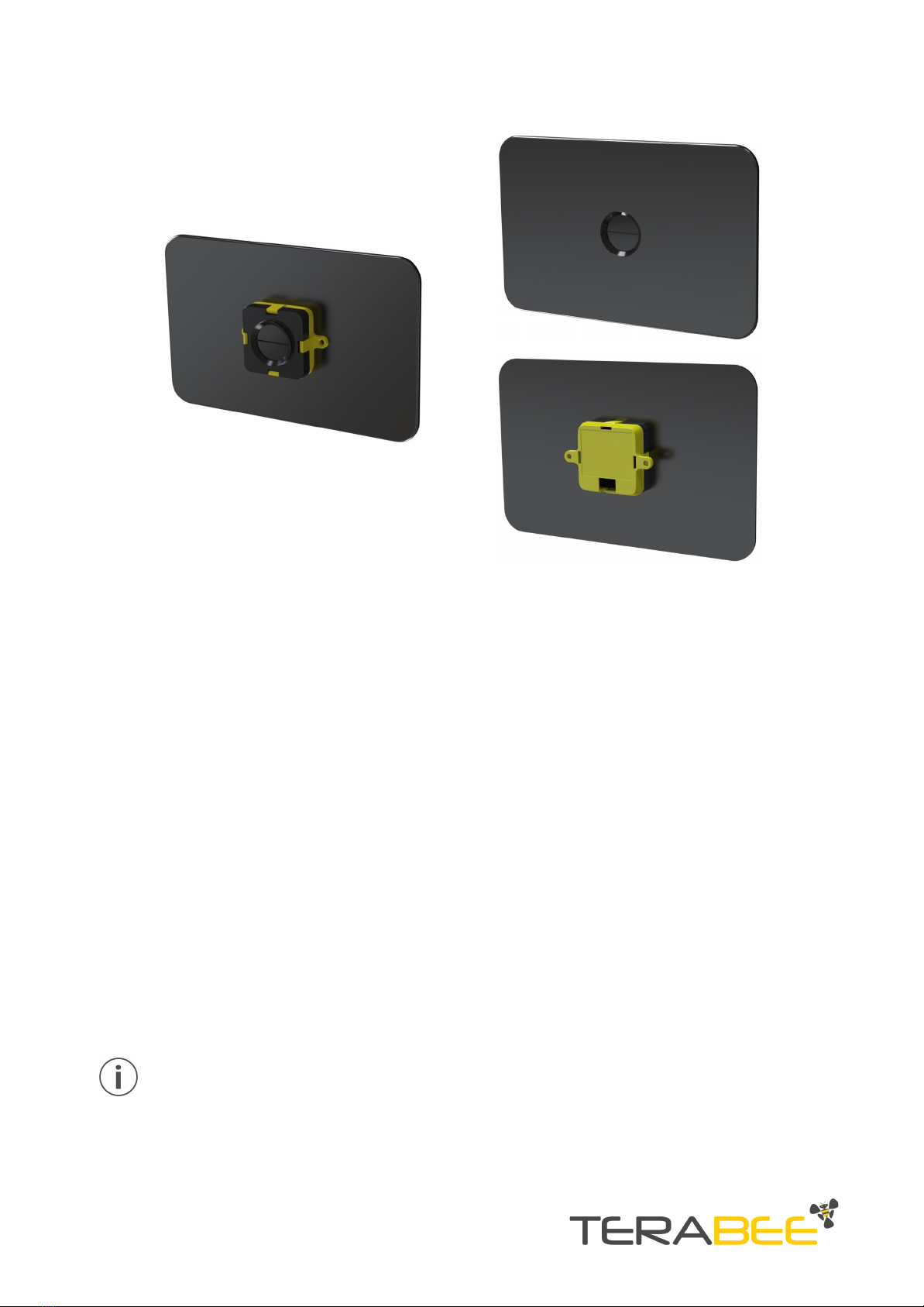
2.2. Mechanical design and mounting 8
2.3. Mounting solutions 10
3. USB backboard use 11
3.1. LED Indication 11
3.1.1. Normal operation 11
3.1.2. Error messages and troubleshooting 11
3.2. Graphical User Interface (version 1.0.31) 12
3.2.1. Prerequisites 13
3.2.2. Basic Operation with the GUI, supporting 1px mode 13
3.2.3 Firmware Upgrade 14
3.3. Connecting the TeraRanger Evo to a Host Computer 15
3.3.1 Windows OS 15
3.3.2 Mac Os 16
4. I2C/UART backboard use 18
4.1. I2C/UART pinout 18
4.2. LED Indicators 19
4.2.1. Normal operation 19
4.2.2.Troubleshooting 19
4.3. Electrical characteristics 20
5. USB/UART Normal operation 20
5.1. USB/UART list of commands 20
5.2. Printout modes: text and binary 21
5.2.1. TEXT mode 21
5.2.2. BINARY mode (default) 22
5.3. Pixel modes: 1px, 2px and 4px 23
5.3.1 1px mode 23
5.3.2 2px mode 23
Copyright © Terabee 2019
Terabee, 90 Rue Henri Fabre
01630, St Genis-Pouilly, France (next to CERN)
2/29

5.3.3 4px mode 23
5.4 Range modes: short-range and long-range 24
5.4.1. Long range mode (default) 24
5.4.2. Short range mode 24
5.5 Error cases 24
6. I2C normal operations 25
6.1 I2C Protocol information 25
6.1.1. Write protocol 25
6.1.2. Read protocol 27
6.2. Error cases 27
7. Build multi-sensor applications 28
8. Optical characteristics 29
8.1. Projected reception area 29
Copyright © Terabee 2019
Terabee, 90 Rue Henri Fabre
01630, St Genis-Pouilly, France (next to CERN)
3/29

1. Introduction
1.1. About Terabee
The smallest and lightest addition to the TeraRanger Evo sensor family provides versatile
performance and value for money! Optimized for indoor distance sensing, Evo Mini offers
ranging capabilities from just 3 cm up to 3.3 m using a 27 degree Field of View. Easily
switch from single-pixel to multi-pixel modes, as well as close-range and long-range modes,
to adapt to your sensing needs.
Figure 1. TeraRanger Evo Mini sensors, top view
Evo Mini has zero open electronics and provides an ABS protected enclosure, resulting into
a dust-proof and robust operation. Benefit from Arduino & Raspberry Pi sample codes and
free ROS packages to get your projects up and running in no time!
1.2. Symbols explanation
The following symbols are used within the document:
This symbol indicates specific recommendations in order to run the sensor in the
intended way.
Copyright © Terabee 2019
Terabee, 90 Rue Henri Fabre
01630, St Genis-Pouilly, France (next to CERN)
4/29

1.3. Technical Specifications
Table 1 - Technical specifications of TeraRanger Evo Mini
Product codes
TR-EVO-MINI-USB / TR-EVO-MINI-I2C
Performance
Detection Principle
Infrared Time-of-Flight
Light Source Wavelength
940 nm
Use Environment
Indoors
Repeatability
< 5 mm
Output Distance Resolution
1 mm
Field of View
27°
Projected Reception Area
48 cm x 48 cm @ 1 m
Operation
Pixel (px) modes: 1px, 2px, 4px (2x2)
Ranging modes: short-range, long-range
Range
Please see “Performance Matrix” table for more details
Accuracy
Update Rate
Electronics
Supply Voltage VDC
5V DC +/-5%
Current Consumption (average)
50mA
Initialization Time
< 1 s
Communication
Serial Interfaces
USB 2.0 Micro-B
UART, +3.3V level, 115200,8,1, None
I2C, +3.3V level, 400 kHz
Visual Notification
2 x LEDs (built-in backboard)
Mechanical data
Dimensions
42 x 30 x 13 mm (incl. backboard)
Weight
9 g (incl. backboard)
Operating Temperature
-20°C to 75°C
Housing Material
ABS
Copyright © Terabee 2019
Terabee, 90 Rue Henri Fabre
01630, St Genis-Pouilly, France (next to CERN)
5/29

Mounting Style
2 holes for M2 screws
Type of Connection
USB Backboard: USB 2.0 Micro-B
I2C/UART Backboard: DF13-7p connector
Hub Evo Backboard for use with TeraRanger Hub Evo
Conformity
CE, RoHS
1.3.1. Performance Matrix
Table 2 - Performance matrix for the different range and pixel modes
Range mode
Short-Range mode
Long-Range mode
Pixel mode
1px mode
2px mode
4px mode
1px mode
2px mode
4px mode
Range
0.03m to
1.35m
0.03m to
1.35m
0.03m up to
1.35m
0.03m to 3.3m
0.03m to 2.3m
0.03m up to
1.65m
Accuracy
Up to
+/-1.5cm
Up to +/-1.5cm
Up to +/- 2cm
Up to +/- 2cm
Up to +/-1.5cm
Up to +/- 3cm
Update Rate
Fixed 40Hz
Fixed 13Hz
Fixed 6Hz
Fixed 20Hz
Fixed 8Hz
Fixed 4Hz
Specifications are derived from tests in controlled conditions (target with 80% diffuse reflectivity, indoor fluorescent lighting,
ambient temperature around 25°C). Note that bright sunlight, target surface reflectivity and other variables can affect sensor
performance
1.3.2 Communication interfaces
Table 3 - Communication interfaces for the different range and pixel modes
Interfac
e
Short-Range mode
Long-Range mode
1px mode
2px mode
4px mode
1px mode
2px mode
4px mode
USB
Yes
Yes
Yes
Yes
Yes
Yes
UART*
Yes
Yes
Yes
Yes
Yes
Yes
I2C*
Yes
Yes
Hub Evo
Yes
*Please note that UART and I2C data communication is supported by the same interface backboard
Copyright © Terabee 2019
Terabee, 90 Rue Henri Fabre
01630, St Genis-Pouilly, France (next to CERN)
6/29

1.4. Pixel modes introduction
The TeraRanger Evo provides 6 operating modes: 3 pixel modes and 2 range modes. For
more details on how to switch between the operating modes, please refer to section 5.
Benefit from 3 distinct pixel modes with 1 pixel resolution, 2 pixel resolution and 4 pixels
(2x2) resolution. Please see table 4 for a visual example for each pixel mode.
Table 4 - TeraRanger Evo Mini operating modes introduction
1px mode
2px mode
4px mode (2x2)
Sensor outputs 1 distance.
Sensor outputs 2 distances.
Sensor outputs 4 distances on
a matrix of 2x2.
Copyright © Terabee 2019
Terabee, 90 Rue Henri Fabre
01630, St Genis-Pouilly, France (next to CERN)
7/29

2. Mechanical integration
2.1. Modular design (clip-on, clip-off)
The mechanical design of the main sensor module (black) allows easy assembly to its
backboard (yellow) using a simple ‘clip-on’ technique. When clipping the two together,
please ensure there is no visible gap between the black and yellow parts.
Figure 2 - modular design of the TeraRanger Evo Mini sensor
2.2. Mechanical design and mounting
TeraRanger Evo Mini distance sensor offers an ABS housing (both: sensor and backboard)
with an option to mount the sensor using 2 holes compatible with M2 screws. Figure 3
illustrates external dimensions of TeraRanger Evo Mini sensor.
Copyright © Terabee 2019
Terabee, 90 Rue Henri Fabre
01630, St Genis-Pouilly, France (next to CERN)
8/29

Figure 3 - TeraRanger Evo Mini external dimensions, USB backboard
Please note that the overall sensor dimensions remain unchanged when using the
I2C/UART backboard. The only affected dimension is the opening of the connector.
Both USB and I2C/UART Backboards include two slots for mounting the sensor using
standard M2 screws. The following methods can be used to mount the TeraRanger Evo
Mini sensor:
1. Front-panel mount using the M2 screws
2. Back-panel mount using the 2mm ledge on the front side of the sensor
Figure 4 illustrates the two different mount methods. The prior solution allows for easy
surface attachment and rapid evaluation of the sensor. The latter provides a more discreet
installation and supports design-in projects by installing the sensor behind a surface (e.g
panel), ideally with 2mm thickness.
Copyright © Terabee 2019
Terabee, 90 Rue Henri Fabre
01630, St Genis-Pouilly, France (next to CERN)
9/29

Figure 4. Front-panel mounting (left image); back-panel mounting (right images)
2.3. Mounting solutions
When choosing a place for mounting the TeraRanger Evo Mini, please consider the
following recommendations:
●Mounting close to sources of heat or strong electromagnetic fields can decrease the
sensing performance
●Do not mount anything directly in front of the sensor or in a cone of approximately
+/-35° around the central optical axis of the sensor
●Within the first meter from the sensor, avoid objects with high surface reflectivity in
a cone of approximately +/-45° around the central optical axis of the sensor
●It is better to avoid having other sources of Continuous Wave or modulated IR light
close to the sensor
●Please consider that dust, dirt and condensation can affect the sensor performance
●It is not advised to add an additional cover in front of the sensor
During assembly and integration, please observe all common ESD precautions. All
optical surfaces (sensor front) should be kept clean and free from contact with
chemicals.
Copyright © Terabee 2019
Terabee, 90 Rue Henri Fabre
01630, St Genis-Pouilly, France (next to CERN)
10/29

3. USB backboard use
3.1. LED Indication
3.1.1. Normal operation
Three LED indicators are present on the USB backboard, and are visible through the back
side of the yellow plastic case.
Table 5 - LED indicators of the USB backboard
LED designator
Description
PWR (ORANGE)
The Power LED is ON whenever the sensor is powered
RED
Flashes briefly on startup to indicate proper initialization;
then switches off
GREEN
Blinks 8 times at power up.
GREEN LED blinks every 5 seconds when the sensor is streaming
distance data
Please note that the number of LEDs and their signalization logic differs between
USB backboard and I2C/UART backboard
3.1.2. Error messages and troubleshooting
Table 6 - USB backboard LEDs troubleshooting
LED
designator
Sequence
Signification
Corrective actions
RED
Continuous
blinking
Sensor has detected a fault
and has stopped functioning
Check that the sensor is
properly connected to the
backboard, then restart the
sensor
RED /
GREEN
Both LEDs
blinking
continuously
Sensor has detected a fault
in the sensor initialisation
process
Check USB output for details
of Error
Verify that the sensor is
properly connected and
re-power the unit
Copyright © Terabee 2019
Terabee, 90 Rue Henri Fabre
01630, St Genis-Pouilly, France (next to CERN)
11/29

RED /
GREEN
Alternate
blinking (red /
green / red /
green / etc)
with 1 s
intervals
Sensor is not initialized
because previous firmware
upgrade was interrupted
Sensor can not be operated
Force a Device Firmware
Upgrade by connecting the
sensor to the Graphical User
Interface and, without
pressing Connect, hold “Shift”
on your keyboard and click on
File > Upgrade Firmware. The
GUI will enter Upgrade Mode.
For more details please refer
to Section 3.2.3.
Please note that the number of LEDs and their signalization logic differs between
USB backboard and I2C/UART backboard
3.2. Graphical User Interface (version 1.0.31)
A free Graphical User Interface (GUI) is available online, providing an easy way to visualize
distance data on your Windows OS. This is useful for demonstration, testing purposes and
checking some of the basic parameters of the sensor. It also provides a way to easily
upgrade the firmware running on the device.
Please ensure you are using GUI version 1.0.3 or later (the current version only supports
sensor’s 1px mode) The TeraRanger Evo Mini GUI is available for download under the
“Downloads” section of the Evo Mini product page, or by following the link below:
https://www.terabee.com/wp-content/uploads/2019/04/TeraRangerEvoInstaller_v1_0_3.exe
If the TeraRanger Evo Mini is used in 2px mode, 4px mode or in Text print out
mode with the GUI, it will not stream any distance. Please refer to Section 5 for
more information about the pixel and print out modes.
Copyright © Terabee 2019
Terabee, 90 Rue Henri Fabre
01630, St Genis-Pouilly, France (next to CERN)
12/29

3.2.1. Prerequisites
For usage on Windows 7 and Windows 8, please download the Virtual COM Port driver
from http://www.st.com/en/development-tools/stsw-stm32102.html and follow the
”ReadMe file” instructions given by the installer. After successful installation, unplug the
interface for a few seconds, and plug it back in. The virtual COM port should now be
available on your PC.
Users of Windows 10 do not need to download this driver as the built-in Windows
driver is recommended.
3.2.2. Basic Operation with the GUI, supporting 1px mode
Make sure your TeraRanger Evo Mini is connected to a USB port on your computer. In the
GUI select File > Connect. You should immediately see a distance reading in millimetres
and the status change to ‘Connected’.
Figure 5 - TeraRanger Evo Mini GUI for 1px mode
Copyright © Terabee 2019
Terabee, 90 Rue Henri Fabre
01630, St Genis-Pouilly, France (next to CERN)
13/29

Each time the TeraRanger Evo Mini is connected to the GUI (powered), the sensor uses its
default configuration parameters (1px mode, binary print out mode). To switch between
other configuration modes please consult section 5 for more details.
In cases when the GUI is not streaming distance data, after successful physical
connection to a personal computer, please reconnect the sensor to the computer
by disconnecting and connecting the sensor. Should the issue persist, please
contact Terabee team at [email protected] for further guidance.
3.2.3. Firmware Upgrade
The following section summarizes steps to upgrade the firmware running on your sensor.
This can be helpful upon a new product firmware release (informed by Terabee) or should
there be a necessity to re-flash your existing device firmware.
The current firmware version on your TeraRanger Evo Mini can be found by
selecting Help > About in the graphical user interface
Please note that the Upgrade Firmware feature is only supported on Windows 7, 8 and 10
OS. Please carefully follow the steps outlined below to enable firmware upgrade and avoid
permanently disabling your device.
Please be advised that wrongful execution of the upgrade functions can result into
permanent sensor firmware deletion
Table 7 - Firmware upgrade instructions
Step
Action
Description
1
Download GUI
Download the latest version of the TeraRanger Evo GUI
on your computer. The GUI is available from TeraRanger
Evo Mini product page. Please refer to section 3.2 for
more details
2
Install GUI
Install the downloaded version of the TeraRanger Evo
GUI on your computer. Please refer to section 3.2 for
more details
3
Download FW
Download the latest Evo Mini firmware file from the
TeraRanger Evo Mini product page, or provided by the
Terabee technical support team
4
Initiate
upgrade FW
procedure
In the GUI, select File > Connect and then File >
Upgrade Firmware.
Click ‘Yes’ in the dialog window to confirm the firmware
Copyright © Terabee 2019
Terabee, 90 Rue Henri Fabre
01630, St Genis-Pouilly, France (next to CERN)
14/29

upgrade procedure
5
Upgrade FW
A new dialog window will present instructions on
selecting the firmware file and launching the upgrade
process. Read the instructions carefully before
continuing.
Press ‘Select File’ and select the new firmware file with
Windows File Explorer
Press ‘Upgrade’ and wait until the operation finishes
6
Close upgrade
FW procedure
Once the upgrade is over, the dialog box shows
“Firmware upgraded” in the bottom left corner. Close the
dialog. The sensor is ready to stream with the latest
firmware.
Note that the dialog box will automatically close after 5
seconds
Once initiated, the upgrade firmware procedure must follow all the steps. If the
procedure exists before finishing, the sensor will switch to error mode. Please refer
to section 3.1.2 for more details
3.3. Connecting the TeraRanger Evo to a Host Computer
3.3.1 Windows OS
In Windows it is also possible to use any terminal emulation software for data display.
Terabee often works with and suggests using HTerm software. Please follow the provided
link to download the software file (http://www.der-hammer.info/terminal/), and select the
version 0.8.2 of the software.
Next, extract the downloaded zip file to the selected folder, open it and double click on the
“HTerm.exe” document. Connect the TeraRanger Evo Mini to a computer and select the
corresponding USB port (click “R” button to refresh the port list). Please configure the
software with the following parameters:
Baud rate : 115200 bit/s
Data bits : 8
Parity bit : None
Stop bit : 1
For easier data reading, select the “LF” option from the “Newline at” drop-down field. See
Figure 6 below for visual instructions.
Copyright © Terabee 2019
Terabee, 90 Rue Henri Fabre
01630, St Genis-Pouilly, France (next to CERN)
15/29

Figure 6 - HTerm parameters for TeraRanger Evo Mini
Once the USB port is selected and the parameters correctly set, click on the “Connect”
button. The distance data will now appear in the “Received data” box (see Figure 7). Please
note that the HTerm emulation software support data stream in all pixel modes, including
1px mode, 2px mode and 4px mode.
Figure 7 - Data stream on HTerm software:
1px mode (left); 4px mode (right)
To communicate with the terminal emulation software, a command in hexadecimal needs
to be sent using the “Type” field. Make sure the “Hex” checkbox is selected (checked) and
the “Type” field has “HEX” as an option selected. Figure 7 shows an example of the
command which allows data to be shown in TEXT mode in 4px mode.
3.3.2 Mac Os
When using a Mac OS it is also possible to use any terminal emulation software for data
display. Terabee often works with and suggests using the Coolterm software. Please follow
the provided link to download the software file (https://freeware.the-meiers.org/).
Next, double click on the “CoolTermMac.dmg” file and then on the Coolterm icon. Connect
the TeraRanger Evo Mini to a computer and click the “Options” button. Select the
corresponding USB port (click “Re-Scan Serial Ports” button to refresh the port list). Please
configure the software with the following parameters:
Baud rate : 115200 bit/s
Data bits : 8
Parity bit : None
Copyright © Terabee 2019
Terabee, 90 Rue Henri Fabre
01630, St Genis-Pouilly, France (next to CERN)
16/29

Stop bit : 1
Figure 8 - Coolterm parameters for TeraRanger Evo Mini
Once the USB port is selected and the parameters correctly set, click on the “Connect”
button. The distance data will now appear (see Figure 9). Please note that the Coolterm
emulation software supports data stream for all pixel modes, including 1px mode, 2px
mode and m4px mode.
Figure 9 - Data stream on Coolterm software:
1px mode (left); 2px mode (right)
To communicate with the terminal emulation software, click Connection > Send String. A
new window opens, allowing to send command to the Evo Mini. Make sure the “Hex”
checkbox is selected (checked) as the command needs to be sent in hexadecimal, and then
Copyright © Terabee 2019
Terabee, 90 Rue Henri Fabre
01630, St Genis-Pouilly, France (next to CERN)
17/29

click the “Send” button. Figure 9 also shows an example of the command which allows data
to be shown in 1px mode or in 2px mode.
4. I2C/UART backboard use
The TeraRanger Evo Mini sensor can be controlled through a UART interface using an
I2C/UART backboard.
Figure 10 - I2C/UART backboard front view
4.1. I2C/UART pinout
The I2C/UART backboard uses a single 9 pin Hirose DF13 connector for interfacing to the
host system. The mating connector is a Hirose DF13-9S-1.25C with crimping contacts
DF13-2630SCF (tin) or DF13-2630SCFA (gold). Please consider the mechanical stability of
the mated connectors and avoid any kind of excess force on the connector (during
installation and once integrated) and follow the recommendations in the Hirose DF13
series datasheet (available here: https://www.hirose.com/product/en/products/DF13) to
ensure a reliable connection.
Table 8 - Pinout and description (According to DF13 datasheet)
Pin
Designator
Description
1
Tx
UART transmit output. 3.3V logic
2
Rx
UART receive input. 3.3V logic
3
GND
Power supply and interface ground
4
SDA
I2C serial data line. 3.3V logic
5
SCL
I2C serial clock line. 3.3V logic
6
rfu
RESERVED FOR FUTURE USE
7
5V
+5V supply input
8
GND
Power supply and interface ground
9
rfu
RESERVED FOR FUTURE USE
Copyright © Terabee 2019
Terabee, 90 Rue Henri Fabre
01630, St Genis-Pouilly, France (next to CERN)
18/29

4.2. LED Indicators
4.2.1. Normal operation
The I2C/UART Backboard has three built-in LEDs behind the yellow case to visualise
feedback of the sensor status. Table 9 lists the functionality of each LED of the I2C/UART
backboard.
Table 9 - LED indicators of the I2C/UART backboard
LED
Description
PWR (orange)
Power indicator, constantly ON when 5V is supplied
Rx (red)
Tx (green)
I2C/UART receive and transmit indicators.
Single blink for each data received or sent
4.2.2. Troubleshooting
Table 10 - I2C/UART backboard LEDs troubleshooting
LED
designator
Sequence
Signification
Corrective actions
RED
Continuous
blinking
Sensor has detected a fault
and has stopped functioning
Check that the sensor is
properly connected to the
backboard,
then restart the sensor
RED /
GREEN
Both LEDs
blinking
continuously
Sensor has detected a fault
in the sensor initialisation
process
Check I2C/UART output for
details of Error
Verify that the sensor is
properly connected and
restart
RED /
GREEN
Alternate
blinking (red /
green / red /
green / etc)
with 1 s
intervals
Sensor is not initialized
because previous firmware
upgrade was interrupted.
Sensor can not be operated.
Run the Firmware upgrade.
Please refer to Section 3.2.3
for more details
Copyright © Terabee 2019
Terabee, 90 Rue Henri Fabre
01630, St Genis-Pouilly, France (next to CERN)
19/29

4.3. Electrical characteristics
Table 11 - TeraRanger Evo Mini power consumption
Parameter
Minimum
Maximum
Average
Power supply
Voltage input (V)
Current consumption (mA)
4.5V
25mA
5.5V
75mA
5V
50mA
Interface logic levels
(referenced to +3V3)
LOW
HIGH
-
2.3
1
-
-
-
5. USB/UART Normal operation
5.1. USB/UART list of commands
Table 12 - List of commands for TeraRanger Evo Mini
Command (HEX)
Command description
00 11 01 45
PRINT OUT MODE TEXT
00 11 02 4C
PRINT OUT MODE BINARY
00 21 01 BC
PIXEL MODE 1PX MODE
00 21 03 B2
PIXEL MODE 2PX MODE
00 21 02 B5
PIXEL MODE 4PX MODE
00 61 01 E7
RANGE MODE SHORT RANGE MODE
00 61 03 E9
RANGE MODE LONG RANGE MODE
Please refer to Section 3.3 for instructions on how to send commands to the TeraRanger
Evo Mini sensor using a host computer and the HTerm emulation software.
Each command message frame must be transmitted in a continuous stream, ie.
not byte by byte
Copyright © Terabee 2019
Terabee, 90 Rue Henri Fabre
01630, St Genis-Pouilly, France (next to CERN)
20/29
This manual suits for next models
3
Table of contents
Other TeraBee Accessories manuals

TeraBee
TeraBee IND-TOF-1 User manual

TeraBee
TeraBee ND-TOF-1 User manual

TeraBee
TeraBee TeraRanger Evo User manual

TeraBee
TeraBee TeraRanger Evo Swipe Plus User manual

TeraBee
TeraBee TeraRanger Multiflex User manual

TeraBee
TeraBee IND-TOF-1 User manual

TeraBee
TeraBee TeraRanger Evo User manual

TeraBee
TeraBee TeraRanger Evo 64px User manual

TeraBee
TeraBee TeraRanger One User manual

TeraBee
TeraBee TeraRanger Evo User manual