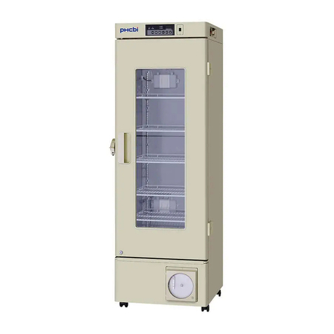
Thermoline Scientific TELR 130 User manual

Copyright 2018 Thermoline Scientic Equipment Pty Ltd
LABORATORY REFRIGERATOR
INSTRUCTION MANUAL
FOR MODELS:
TELR 130/145/200/440/740
TLR 520/750/950/1150
Fitted with Dixell XR70 Controller
REVISION 19/4/2018 (1.5)
1

Copyright 2018 Thermoline Scientic Equipment Pty Ltd
PRE USE CHECKLIST
Read this manual
All packaging removed
Ensure correct ventilation distances (Refer to Page 5)
Unit on level ground
Appliance Tested/Tagged as per site guidelines
BMS Connected (if tted)
Data logger placed in cabinet (if being used)
Unit powered on and doors not opened for at least 8 hours.
2

Copyright 2018 Thermoline Scientic Equipment Pty Ltd
Thank you for choosing a Laboratory Refrigerator from Thermoline Scientic.
This manual covers the operation, cleaning, & maintenance instructions for this equipment.
Incorrect operation or use can cause harm or damage to the equipment and it’s contents, therefore it is very important that
you read, understand, and implement the instructions, to ensure reliable operation.
Please keep this manual in a safe place for future reference.
List of Contents Page
INTRODUCTION 3
LIST OF CONTENTS 3
UNPACKING 4
USE AND FUNCTION 4
LOCATION & INSTALLATION
• Location:
• Level:
• Castors:
• Mains connection:
5
OPERATION:
• Temperature control:
• Loading:
• Connection of alarms
• Maximum and minimum temperature logging:
• Calibration
• Optional Chart Recorder.
• Optional Low Temperature Protective Cut-out.
6-8
CLEANING & MAINTAINANCE 9
TROUBLESHOOTING 10
SERVICING 11
SPARE PARTS
REFRIGERANT CHARGES
11
WIRING DIAGRAMS 12-14
WARRANTY 15
INTRODUCTION
3

Copyright 2018 Thermoline Scientic Equipment Pty Ltd
Remove the equipment from the packing material and check for damage. Notify the detail of any damage to your supplier or
to Thermoline Scientic without delay.
Retain the packing materials until the equipment has been thoroughly tested.
Inventory:
• Shelves and shelf support clips include std quantities.
• 1 x 3-pin plug for connection of alarms to remote Building Monitoring System (BMS).
• Door keys.
• Chart recorder keys and paper. (Only if optional chart recorder is supplied).
The Thermoline range of Laboratory refrigerators are designed to store temperature sensitive products within an adjustable
temperature range. This product is identied by a label on the front of the unit as shown below:
This products’ intended use is for the storage of temperature sensitive products. It CANNOT be used as a pharmacy or
vaccine refrigerator.
All TELR/TLR Refrigerators have loading requirements. When loading, product should be evenly distributed throughout the
refrigerator. It is important to leave 1/3 of each shelf level free (3cm front, side, rear and between products) this allows air to
ow evenly throughout the cabinet and maintain temperature accuracy in the refrigerators workspace.
The digital temperature control monitors product temperature, and includes a temperature logging feature that allows the
operator to determine the maximum and minimum temperatures reached during daily operation.
When correctly maintained, the refrigerator has an expected lifespan in excess of 5 years. Regular maintenance and checks by
a licensed refrigeration technician will help extend the life of the unit.
The display also incorporates the HI/LO temperature alarms emitting both visual and audible signals, which can also activate a
building monitoring system (BMS), via a connection socket on the cabinet.
High temperature alarm set at 1ºC above setpoint.
Low temperature alarm set at 1º C below setpoint.
Operating temperature set between +4 & +10º C.
These cabinets will operate from a standard 10 amp, 240 volt, 50Hz, general purpose outlet (power point). Cooling is by means
of a hermitically sealed refrigeration unit using environmentally friendly refrigerant.
Fan forced air circulation internally ensures that even temperature conditions are obtained on all shelf levels. The controller
monitors the temperature inside of the workspace. The control sensor is located in a bottle that simulates product, this give a
more accurate reading of the temperature inside of the workspace.
UNPACKING
USE & FUNCTION
4
Laboratory Refrigerator

Copyright 2018 Thermoline Scientic Equipment Pty Ltd
All refrigerated equipment generates heat as part of the normal operation. It is vital for correct performance and reliability
that adequate ventilation is provided to allow this heat to dissipate.
Any refrigerated equipment that is operated in a small unventilated area, especially in warm weather, can
cause the compressor to overheat and may result in premature failure.
NOTE: Failure to observe ventilation guidelines will void the manufacturer’s warranty!
All TELR/TLR Refrigerators require ventilation around them. 100mm (10cm) on each side and the back is re-
quired. See diagrams below showing correct placement and ventilation distances.
LOCATION & INSTALLATION
I
Do not store items on top of the fridge as this will also aect ventilation!
Level:
The cabinet should be standing on level ground to ensure correct operation of the self-closing door, and proper draining of
condensate from the evaporator (internal cooling surface).
Castors:
Where lockable castors are tted they must be locked to prevent accidental cabinet movement. This can be achieved by press-
ing the lock-down tab with your foot. Ensure that both castors are locked.
Mains connection:
This cabinet is suitable for connection to a standard 10Amp, 240 volt, 50Hz, supply. A dedicated outlet should be used for the
supply, do not use power boards or the like. A 3-pin moulded plug is tted as standard to the mains lead.
5
TLR 520, 750, 950, 1150TELR 130, 145 TELR 200, 440, 740

Copyright 2018 Thermoline Scientic Equipment Pty Ltd
1: Locate the cabinet as previously described, and plug the mains lead into the power supply but do not turn the power on
just yet.
2: The cabinet is supplied with the shelves xed in place. Adjust the shelf positions to suit your storage needs by moving the
support clips provided.
3: Turn on the power and the circulating fan inside the cabinet will start immediately. You should also be able to turn on the
internal light using the “light” switch on the front panel.
4: After a short warm-up period, the temperature control will display the temperature inside the refrigerator. The refrigeration
compressor will start after a few minutes.
5. Allow the cabinet to reach operating temperature and to operate for at least 8 hours prior to loading stock.
OPERATION
TEMPERATURE CONTROL
Information/set point
button. Hold for 5 seconds
to change setpoint. Mute
Alarm
Decrease button – To view
the minimum recorded
temperature. To lower
setpoint. Mute Alarm
Increase button – To view
the maximum recorded
temperature. To increase
setpoint. Mute Alarm
Exit/Mute Alarm.
To Change the setpoint - Press and hold for 5 seconds. Then press the or to the desired setpoint.
Then to save press the button.
The temperature control has been factory set to operate between +4ºC & +10°C, and the instrument has been calibrated
to provide a consistant temperature throughout the workspace. The alarms are set to operate @ 1ºC below setpoint for low
alarm, and 1ºC above setpoint for high alarm. Any button can be pressed to mute the alarm. Once muted the alarm will NOT
resound.
During an Alarm Condition the display will show the following:
Message Cause Explaination / Action
P1 Probe 1 Failure Call Service
P2 Probe 2 Failure Call Service
P4 Probe 4 Failure Call Service
HA High Alarm - Product Temperature Probe in bottle is 1°c above setpoint
LA Low Alarm - Product Temperature Probe in bottle is 1°c below setpoint
DA Door Open Alarm Door not closed securely
6

Copyright 2018 Thermoline Scientic Equipment Pty Ltd
As previously mentioned, this cabinet is tted with a 3-pin socket on the cabinet to allow for connection to a building moni-
toring system (BMS), or to a phone dialer. A plug is also supplied separately to connect the socket to your wiring. The alarm
contacts have no voltage present, but we recommend that the wiring is connected by a suitably qualied technician (electri-
cian or similar).
An alarm can be triggered by one of the following conditions:
• Loss of power.
• High temperature inside the refrigerator (1ºC above setpoint).
• Low temperature inside the refrigerator (1ºC below sepoint).
CONNECTION OF ALARMS
*Normally Closed
Will open loop upon alarm
situation (No 1) *This is the
optimum option as any break
in the loop is detected.
Normally Open
Will close loop upon alarm
situation (No 2)
Common
At least one wire is connected
to this pin (No 3)
All forced draught refrigerators such as this one requires constant air ow throughout the cabinet to maintain the desired
temperature. Correct loading of the shelves must be considered for ecient refrigeration performance.
• Never block o air vents in the rear panel if tted.
• Allow air space around the product on each shelf.
• Distribute the load evenly over all of the shelves rather than stacking everything on one shelf.
• Whenever possible the load should be chilled prior to loading to reduce the eect on the temperature inside
the refrigerator. If this is not possible then load the product a little at a time.
• All TELR/TLR Refrigerators have loading requirements. When loading, product should be evenly distributed
throughout the refrigerator. It is important to leave 10% of each shelf level free (3cm front, side, rear and between
products) this allows air to ow evenly throughout the cabinet and maintain temperature accuracy in the refrigerators work-
space.
LOADING
I
7
CALIBRATION
Calibration of the unit ensures correct product temperature and optimal refrigerator perfrormance. Calibration should be
done by a trained technician.
Press and hold + the following parameters will be available
Ot - Sensor Oset in Bottle
OE - Return Air Sensor Oset
O4 - Low Temp Alarm Sensor Oset
dP1 - Current Temperature of the Bottle Sensor
dP2 - Current Return Air Temp
Calibration is normally performed at 5°C. This procedure is a standard procedure used by Thermoline Scientic.
The aim when calibrating a Thermoline Laboratory Refrigerator is to have the Bottle at 5°c. This is acheived by placing a refer-
ence sensor in the bottle or in a bottle adjacent to the units bottle and noting the indicated temperature. The OE parameter is
then adjusted to increase or decrease the air temperature until the reference sensor reads 5°c.
Once the reference sensor has an average temperature of 5°c adjustments to Ot are made so that dP1 (Display Temperature)
equals 5°c.

Copyright 2018 Thermoline Scientic Equipment Pty Ltd
The digital temperature control has a feature that allows the operator to log or record the maximum and minimum tempera-
tures attained by the cabinet over a period of time. These logged temperatures can be reset on a daily basis by simply pressing
the buttons on the face of the instrument as follows:
i) Press and release the “UP” button until ‘Hi’ appears. This is ‘MAX’ temp logged.
ii) Press and hold the “SET” button until RST appears the maximum logged temperature will then be reset.
iii) Press and hold the “DOWN” button until ‘Lo’ appears. This is ‘MIN’ temp logged.
iv) Press and hold the “SET” button until RST appears the maximum logged temperature will then be reset.
TEMPERATURE LOGGING
A circular chart recorder can be factory tted as an optional extra. The recorder has a seven day chart with a battery back-up
that will keep the chart running for at least twenty four hours in case of a power failure.
To set the time:
• Unlock the recorder door using the key supplied.
• Raise the nib o the chart paper by pushing the lever at the top right corner.
• With the pen nib lifted o the paper, insert a coin into the slot in the centre of the spindle, and turn it ANTICLOCKWISE ONLY!
• Note: It is easier to set the time when the refrigerator is at the set temperature, this will enable you to determine the time
more accurately.
• Carefully remove the pen nib cover by gently turning it as you pull it o the nib.
• Lower the nib onto the chart and close the clear lid with the key provided.
OPTIONAL CHART RECORDER (IF FITTED)
To replace the chart paper (weekly):
• Raise the nib o the paper by pushing the lever at the top right corner.
• Replace the chart paper by simply pulling the edges of the chart out from under the three locating tabs.
• Place the new chart over the slot in the spindle taking care not to tear the chart as you do it, and t the outer edges of the
chart back under the locating tabs to keep it in place.
• Lower the nib onto the chart and close the door using the key provided.
8
OPTIONAL LOW TEMPERATURE PROTECTIVE CUT-OUT (LTPC) (IF FITTED)
Low Temperature Protective Cut-out:
As an added safety feature the refrigerator can be factory tted with a low temperature
protective cut-out, which is factory set and not adjustable, to stop the temperature inside
the refrigerator from falling below 0ºC. This is particularly important in the storage of vaccines which can be destroyed if
frozen.
The cut-out operates independently from the temperature control and turns o the compressor at +1 to +2ºC. In this way,
should the controls fail in a“cooling”condition; the product will be protected against freezing.
For testing and calibration of the LTPC contact your service technician.

Copyright 2018 Thermoline Scientic Equipment Pty Ltd
General cleaning:
The interior, exterior, and door gasket can be cleaned as often as required using a soft cloth and soapy water. Never use abra-
sive cleaners or scouring pads as these will scratch the surface and may result in corrosion. Never use caustic type cleaning
agents.
All cabinets have electrical components such as the temperature control, internal light, refrigeration condens-
ing unit. These items should not be subjected to any levels of moisture. For example, do not use a hose to
wash down the refrigerator. Evidence of moisture entry into any electrical device will void the manufacturer’s
warranty!
Maintenance:
Apart from normal levels of cleanliness, it is important that the refrigeration condenser is kept clean and free from dust.
Failure to keep the condenser clean could lead to higher temperatures inside the cabinet, higher running costs, and often a
failure of the compressor. A clean condenser is a critical factor in keeping the refrigerator operating correctly.
The condenser should be cleaned at least every 6 months, in some dusty locations this may need to be more frequent. By
monitoring the amount “clogging” due to dust, the frequency of cleaning can be adjusted to keep it clean.
Manufacturer’s warranty does not cover the failure of the compressor due to a blocked condenser.
CLEANING & MAINTENANCE
I
Procedure for cleaning the condenser:
• The condenser is located in dierent areas depending on the model. The TELR-145 condenser is located on the rear of the
unit as seen in the rst image below. TELR 200, 440 & 740 have a cover at the base of the cabinet which can be removed to
access the condenser for cleaning. The cover unclips from the bottom and has two locating pins at the top to secure it in place.
The TLR range have the condenser located at the top of the cabinet behind the front panel. To remove this panel, push upward
and pull it away from the cabinet.
• Turn o the power at the power point before cleaning the condenser!
• Using a sti paint brush, carefully remove dust and dirt build-up from the condenser, ensuring that dust is not pushed back
into the condenser ns. The use of a vacuum cleaner will help in cleaning up the dislodged material.
9
TLR 520, 750, 950, 1150TELR 145 TELR 200, 440, 740
• The condenser ns may be sharp, take care to avoid personal
injury by not directly contacting them with your hands!
• The n material is thin and can be easily bent, take care not to
atten the ns as this may aect the eciency of the condenser.
I

Copyright 2018 Thermoline Scientic Equipment Pty Ltd
TROUBLESHOOTING
PROBLEM POSSIBLE CAUSE ACTION
Cabinet not working:
No display.
No fans or
refrigeration
Loss of power. Check that the mains lead is
plugged in.
Check that the power point is
working.
Cabinet temperature
too high.
Condenser blocked.
Poor ventilation around
cabinet.
Refrigeration fault.
Evaporator iced up.
Temperature set too high.
Oset Incorrect.
Clean condenser.
Refer to section on location &
installation.
Call service engineer.
Door not closed properly.
Check for overloading.
Call service engineer.
Cabinet temperature
too low.
Temperature set too low.
Refrigeration control fault.
Oset Incorrect.
Set temperature correctly.
Call service engineer.
Call service engineer.
Temperature display
indicates “P1”,”P2” or
“P3” alarm.
Faulty temperature sensor. Call service engineer.
Water on door or
inside of cabinet.
High Humidity
Door Left open
Door gasket split or
damaged
Reduce ambient humidity
Ensure door closes (check for
obstructions preventing the
door from closing and cabinet
is level)
Call service engineer.
10

Copyright 2018 Thermoline Scientic Equipment Pty Ltd
SERVICING
General Servicing:
General inspection of the refrigerator should be made at regular periodic intervals depending on a range of factors. Generally
every 6 months the following tasks should be performed:
- Inspect and clean condenser
- Check door gasket for damage including splits, tears or areas where it isn’t sealing to the refrigerator frame when the door is
closed.
- The door self closes when opened to a 90° angle
Apart from normal levels of cleanliness, it is important that the refrigeration condenser is kept clean and free from dust.
Failure to keep the condenser clean could lead to higher temperatures inside the cabinet, higher running costs, and often a
failure of the compressor. A clean condenser is a critical factor in keeping the refrigerator operating correctly.
The condenser should be cleaned at least every 6 months, in some dusty locations this may need to be more frequent. By
monitoring the amount “clogging” due to dust, the frequency of cleaning can be adjusted to keep it clean.
Manufacturer’s warranty does not cover the failure of the compressor due to a blocked condenser.
SPARE PARTS LISTING
TELR
145
TELR
200
TELR
440
TELR
740
TLR
520
TLR
750
TLR
950
TLR
1150
EVAPORATORS 145-EV 200-EV 440-EV 740-EV 520-EV 750-EV 950-EV 1150-EV
EVAPORATORS FAN MOTORS 145-EVF 200-EVF 440-EVF 740-EVF 520-EVF 750-EVF 950-EVF 1150-EVF
CONDENSER FAN MOTORS 145-CF 200-CF 440-CF 740-CF 520-CF 750-CF 950-CF 1150-CF
CONDENSING UNITS 145-CU 200-CU 440-CU 740-CU 520-CU 750-CU 950-CU 1150-CU
CONTROLLERS DX-PR DX-PR DX-PR DX-PR DX-PR DX-PR DX-PR DX-PR
DOOR GASKETS 145-DG 200-DG 440-DG 740-DG 520-DG 750-DG 950-DG 1150-DG
All spare part orders will require a valid cabinet serial number.
REFRIGERANT CHARGES
TELR
145
TELR
200
TELR
440
TELR
740
TLR
520
TLR
750
TLR
950
TLR
1150
134a 120gm 280gm 360gm 360gm 420gm 420gm 550gm 550gm
All above weights are indicative and charging by weight until
sweating on the suction line 200mm before entry back to the
compressor is a proven way to ensure the optimal refrigerant
charge is performed.
11

Copyright 2018 Thermoline Scientic Equipment Pty Ltd
WIRING DIAGRAMS
12

Copyright 2018 Thermoline Scientic Equipment Pty Ltd
13

Copyright 2018 Thermoline Scientic Equipment Pty Ltd
14

Copyright 2018 Thermoline Scientic Equipment Pty Ltd
Have the following information available when you contact the service department:
• Model number and serial number. This is generally found on the exterior of the cabinet in the form of a stick-on label.
• The company name, address, contact name, contact phone number.
• A brief description of the problem.
All warranty claims must be reported to, and agreed to by a Thermoline representative prior to any work being carried
out.
Standard 12 Month Warranty
Thermoline Scientic Equipment Pty Ltd ABN 80 000 859 129 (“Thermoline”)
Thermoline warrants to the original purchaser that this product will perform to its product specication for a period of 12
months from date of purchase, provided that the installation of the product has been carried out in accordance with the latest
version of the manufacturer’s instructions and further provided that the use of the product complies with that specied in the
relevant specication. Thermoline is not responsible for any loss or damage arising from incorrect usage, usage outside the
suitability of the product as stipulated in the manufacturer’s instruction, damage caused by accident, re, ood, act of God or
failure to properly install, operate or maintain the goods in accordance with the printed instructions provided.
The following statement applies only to product sales that fall within the denition of a Consumer Sale set out in the Austral-
ian Consumer Law contained within the Competition and Consumer Act (Cth) 2012:
‘Our goods come with guarantees that cannot be excluded under the Australian Consumer Law. You are entitled to a replace-
ment or refund for a major failure and for compensation for any other reasonably foreseeable loss or damage. You are also
entitled to have the goods repaired or replaced if the goods fail to be of acceptable quality and the failure does not amount to
a major failure.’
Notwithstanding the preceding clause and to the extent permissible by law, the liability of Thermoline is limited, in relation to
the warranted product and at the option of Thermoline to:
• replacing the product or the supply of equivalent product;
• the repair of the product;
• the payment of the cost of replacing the product or of acquiring equivalent product; or
• the payment of the cost of having the product repaired.
To the extent permitted by law, all other warranties whether implied or otherwise, not set out in this Warranty are excluded
and Thermoline is not liable in contract, tort (including, without limitation, negligence or breach of statutory duty) or other-
wise to compensate the Purchaser for:
• any increased costs or expenses;
• calibration/certication services;
• any loss of prot, revenue, business, contracts or anticipated savings;
• any loss or expense resulting from a claim by a third party; or
• any special, indirect or consequential loss or damage of any nature whatsoever caused by Thermoline’s failure in complying
with its obligations or the purchaser’s failure due to accident damage, impact, misuse or negligence.
The benets given to the purchaser in this Warranty are in addition to other rights and remedies under a law in rela-
tion to the products or services to which this warranty applies.
This warranty applies only to products purchased and installed in Australia and does not cover any consumable items
e.g. lters, light globes, ultrasonic nebulizers. The warranty does not extend to labour and freight costs where the
warranted product is located outside Australia.
To make a warranty claim, please ll in the online warranty claim form. All warranty claims must be in writing for us to
document in our quality management system.
WARRANTY
Head Oce Phone (02) 9604 3911
Head Oce Fax (02) 9725 1706
Email info@thermoline.com.au
Web www.thermoline.com.au
15
This manual suits for next models
8
Table of contents
Other Thermoline Scientific Laboratory Equipment manuals
Popular Laboratory Equipment manuals by other brands
Biotechne
Biotechne ProteinSimple Milo installation guide
Opticon
Opticon NLV-5201 user manual

Thermo Scientific
Thermo Scientific FOCUS GC Site preparation and installation manual

Takara Bio
Takara Bio Thermal Cycler Dice Real Time System III Instrument manual
9dot
9dot 8INJ manual

BrandTech
BrandTech accu-jet pro operating manual
