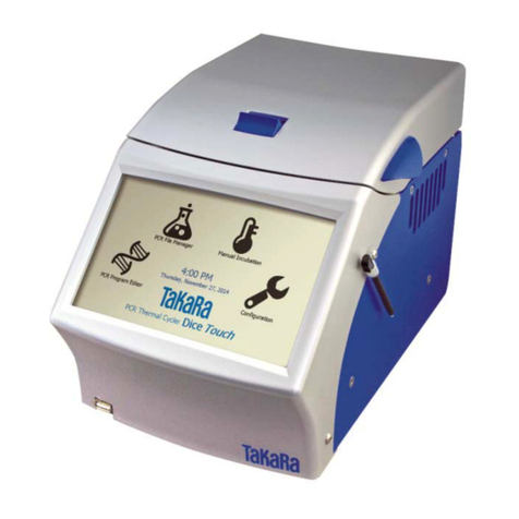
Takara Bio Thermal Cycler Dice Real Time System III User manual

Thermal Cycler DiceTM
Real Time System III
Model TP950/TP970/TP980/TP990
LCD application software V 1.00
Real Time System Software V 6.00
OS:Windows 7 / 8.1
Instrument Manual
TAKARA BIO INC.
Attention: Thermal Cycler DiceTM Real Time System Instrument Manual
should be stored for reference in a secure and accessible location.

This document applies to installation, maintenance and
troubleshooting of the Thermal Cycler DiceTM Real Time System III .
Thermal Cycler Dice Real Time System III (Cat.# TP950)
Thermal Cycler Dice Real Time System III with PC (Cat.# TP970)
Thermal Cycler Dice Real Time System III with PC/MRQ (Cat.# TP980)
Thermal Cycler Dice Real Time System III (Cy5) with PC (Cat.# TP990)
<Software of TP951 main body >
Thermal Cycler Dice Real Time System III LCD application software version 1.00
Thermal Cycler Dice Real Time System III Software version 6.00 for PC
(Cat.# TP952)
OS:Microsoft®Window®7 (32bit) / Windows®8.1 (64bit)
* Not confirm on the Windows®8
Microsoft®Office 2007 / 2010 / 2013
NOTICE
L47 Real-Time PCR Quantification Method
The purchase of this product includes a limited, non-transferable license for all fields other than human
or veterinary in vitro diagnostics under specific claims of U.S. Patent Nos. 6,174,670, 6,569,627,
6,303,305, and 6,503,720, owned by the University of Utah Research Foundation and licensed to Idaho
Technology, Inc. and Roche Diagnostics GmbH.
* Thermal Cycler Dice is a trademark of TAKARA BIO INC.
* Microsoft, Windows, Windows Vista, Excel and PowerPoint are registered trademarks of Microsoft
Corporation.
* FAM and ROX are trademarks of Applera Corporation or its subsidiaries in the US and/or certain
other countries.
* SYBR is a registered trademark of Molecular Probes, Inc.
* All marks are the property of their respective owners. Certain trademarks may not be
registered in all jurisdictions.
Copyright© 2015 by TAKARA BIO INC., KUSATSU, Shiga, Japan
Rev. J

TP950 Instrument Manual
Rev. J
=Contents =
page
PrecautionsforUsing TaKaRaScientificInstruments -- 2
Chapter1: Outline -- 7
Chapter2: Installation Requirements andMaintenance -- 10
1.InstallationConditions -- 10
2.OpeningthePackaging -- 11
3.Installation -- 13
4. Moving theSystem -- 15
Chapter3: Part Names andFunctions -- 16
Chapter4: Explanation of Screens -- 21
1. SystemStartupandShut Down -- 21
2. Home Screen -- 23
Chapter5: Maintenance -- 24
1. Self-diagnostic Function -- 24
2. Daily Inspection -- 27
《Sample Block Cleaning 》-- 28
Chapter6: Other Settings -- 31
1. Enter “Other setting”-- 31
2. Explanation of eachfunction -- 32
Chapter7: Troubleshooting -- 35
《Computer settings 》-- 39
Chapter8: Specifications -- 40
Chapter9: Consumption -- 42
Appendix : Software install/ uninstall App(1) 1~9

2
Precautions for Using TaKaRa Scientific Instruments
●Users arerecommendedtocarefullyreadthecontentof thismanualbefore operating theTaKaRaPCR
ThermalCycler Dicesystem.
●After familiarizing themselves with the informationin this manual, users arerecommended tostoreit in
secure andconvenient location from whichitis always availablefor reference
Introduction
All Takarascientificinstrumentsaresoldstrictlyforuse inresearchapplicationsandshouldnotbe
used bythose who are notexpertsin this field.
Due toongoingimprovements,productspecificationsandtheexternalappearancearesubjectto
change withoutpriornotification.
Warranty and Responsibilities
Referto theWarrantycardincludedwith thisproductfor detaileddescriptionof theWarranty
conditions andperiod.
This product isdesigned toultimate safetystandards.Nevertheless,shouldanysafety-related issues
arise,usersarerequestedtoimmediatelycontact thenearestsalesagent.
Precautions (safety and accident prevention) for System Use
(1)DangerWarnings
The various messagesandlabelsprovidedonthe productitself and in the variousmanualsare
designed toensurethesystemis operatedsafelytopreventpersonalinjury ordamagetoproperty.
Usersarestronglyrecommendedtoreadandobserve the warningsincluded withthesymbols
shownbelow.
Warnings indicate incorrect system operation and
handling procedures that can lead to serious
accidents.
Cautions indicate incorrectsystem operation and
handling procedures that can lead to accidents.
!
CAUTION
!
WARNING

3
(2)General Precautions Regarding Takara Scientific Instruments
Itisimportanttoobservethevariousprecautions describedbelow toensureoptimumsystem
performance and preventaccidentsbefore theyhappen.Ensuresafeandcorrectsystem operation
by carefullyreading the precautions.
【Precautions for Installation Location】
Observe thefollowingprecautionsinorderto preventfiresand electrical shocks.
●Donotinstall the system onanunstable orslopedfoundationorany
otherlocationsubjectunstable conditions.
●Ifthesystemtips overorfalls,immediatelyturnoff powerto the
systemand all connecteddevicesanddisconnectthe power supply
cables.
●Avoid blocking the paths toanyairventsincluded ontheproduct.
Blockedairventscanleadtointernal overheatingthatmayresultin
physical burnsor fire.
●Avoid installing thesysteminlocationssubjecttodustor strong
vibrations.
●Avoid installinginlocationssubjecttodirectsunlightandwide
temperaturefluctuationsas thismayresultininternaloverheatingand
maycausephysical burns orfire.
●Donotplaceobjectsontopof thesystem.
●Donot install thesystemin locationsotherthanresearch institutions or
related facilities.
【Electrical Precautions】
Observe thefollowingprecautions when usingelectricallypowered scientific instruments inorder to
preventelectric shocks andfires.
●Avoid operatingsystem withpowersourcesthatdo notconformto
systempowersupplyspecifications.
●Avoid sharplytwisting,altering,markingorotherwisedamagingthe
powersupplycable.Avoid applyingstress to,heating orplacing
objects on thepowercable.
●Alwaysgroundthesystemto preventelectricshocks due toleakage
current.
!
WARNING
!
CAUTION
!
WARNING

4
●Besure tocomparesystempowersupplyrequirementswiththerated
powercapacityofthepowersourcetoensure systemcurrent
requirements do not exceed power socketcapacity. Confirm that the
totalpowerrequirements ofallconnectedequipmentdonotexceed
the rated power supplycapacityof thecommonpower source.
●Thesystembodyand powersupplycableare subject tohighvoltage
levels(The maximumvoltage is aline voltageAC100V~240V).Avoid
insertingmetalorflammableobjectsinside thesystem orhandling it
withwethands,as this canresultinelectricshock and/orother
dangers.
●When moving the system,be sureto firstdisconnectthepowercable
as well as anyperipheraldevices.
●Besure todisconnect thepower cablepriortocleaningorservicing
the system.
【Other precautions】
Observe thefollowingprecautionsinorderto preventelectric shocksandfires.
●Avoid insertingmetal objects,flammablematerialsorotherforeign
objects into the variousopeningson the systemcase.
●Neverremovethesystem coverorattempt toalteritin anyway.
●Avoid disassemblingormakinganydirectcontact withinternal partsof
the system.
●Shouldnoxiousfumessmokeorotherabnormal signsappear,
immediatelyterminate operation,turnoffsystempowerand
disconnectthepowercable.
Waituntil conditions stabilize before contactingthenearestsales
agentorthecompanytechnical supportline.
●Shouldwaterorotherforeign matterenterthesystem,immediately
terminateoperation,turnoffsystempowerand disconnectthepower
cable.
Waituntil conditions stabilize before contactingthenearestsales
agentorthecompanytechnical supportline.
●Donot siton the system.
●Donotdisassemble thesystem
!
WARNING
!
CAUTION
!
WARNING
!
CAUTION

5
(3)WarningSafetyLabels Applied to System Case
Usersareadvised toavoid accidentsby carefullyreadingthe warningsand cautionscontainedon
warning stickersatkeylocationson theinteriorandexteriorof the system.
Possible
Danger
WarningType
Location ofDanger
Type d’Avertissement
LocalisationduDanger
WarningLabel
Description of
Danger
Electric
shocksand
fires
Disassembly
Prohibited
System Interior
Démontage Interdit
Intérieur de l’Appareil
Neverdisassemble
system, as this may
leadtoelectrical
short-circuits,
leakagecurrent
and/orfire.
Electric
shocks
Warning! High
Voltage
Power cable
Attention!Haute
tension
Cordon d’alimentation
Thecaseandpower
cablearesubjectto
highvoltagelevels,
so takecareto avoid
electricshocks.
Burns
High Temperatures
Heat cover
&Heatblock
HauteTempérature
CouvercleChauffant
Avoid touchingthe
heatcover,which
reaches veryhigh
temperatures and
maycauseburns.
Pleasebesure touse0.1mL-type forthereaction tubeand the reactionplateusedbythis
equipment.
When 0.2mLtypeisinserted bymistake,itcan'tbe takenanymoreout.
PleaseuseconsumablesofTakarabiorecommendation.
Caution
Note
WarningLabel
Description
Lid does
notmove
smoothly.
Reaction
abnormality
Using0.1mLtubes
and96wellplate
Do notuse0.2mL
volumetype.
Pleaseuse0.1mLtype
forareactiontube anda
reaction plate withthecut
forleftbackcorner. It is a
fear that catches on alid
of equipmentfor
0.2mL-type.

6
Thissymbolmeanscaution or warning.
Thissymbolmeansan actionis prohibited.
Thissymbolmeansan instructionmustbefollowed.
(4)ElectricalSymbols
Thissymbolindicates the on position of the mainpowerswitch.
Thissymbolindicatestheoffpositionofthemainpowerswitch.
Precautions against Transferring or Copying Content of This Document
Thecontentof thisdocumentcannotbetransferredorcopiedwithout theexpresspermissionof the
copyright holder.
Copyrightholder: TAKARABIO INC.
Printed in Japan
Contact TAKARA BIO INC.
TAKARABIO INC.
NOJIHIGASHI7–4-38,KUSATSU,SHIGA,525-0058, JAPAN
http://www.takara-bio.com
TechnicalInquiries (Contact):
URL:http://www.takara-bio.co.jp/english/index.htm

TP950 Instrument Manual
Rev. J 7
●Chapter 1: Outline
Thank you for purchasing the Thermal Cycler Dice™Real Time System III.
This system consists of the following components:
<TP950> Thermal Cycler Dice™Real Time System III
1. Thermal Cycler Dice™Real Time System III Main Unit (Code: TP951)
2. Thermal Cycler Dice™Real Time System III Software (Code: TP952)
(1) Real Time System Software (for Research)
(2) Food Environment Inspection Software (Japanese only)
<TP970> Thermal Cycler Dice™Real Time System III with PC
1. Thermal Cycler Dice™Real Time System III Main Unit (Code: TP951)
2. Thermal Cycler Dice™Real Time System III Software (Code: TP952)
(1) Real Time System Software (for Research)
(2) Food Environment Inspection Software (Japanese only)
3. Thermal Cycler Dice™Real Time System Control Computer (Code: TP820)
<TP980> Thermal Cycler Dice™Real Time System III with PC/MRQ
1. Thermal Cycler Dice™Real Time System III Main Unit (Code: TP951)
2. Thermal Cycler Dice™Real Time System III Software (Code: TP952)
(1) Real Time System Software (for Research)
(2) Food Environment Inspection Software (Japanese only)
3. Thermal Cycler Dice™Real Time System Control Computer (Code: TP820)
4. Multi plate RQ Software (Code: TP840)
<TP990> Thermal Cycler Dice™Real Time System III (Cy5) with PC
1. Thermal Cycler Dice™Real Time System III Main Unit (Code: TP951)
2. Thermal Cycler Dice™Real Time System III Software (Code: TP952)
(1) Real Time System Software (for Research)
(2) Food Environment Inspection Software (Japanese only)
3. Thermal Cycler Dice™Real Time System Control Computer (Code: TP820)
4. Filter Unit Cy5 for LED (Code: TP703)

TP950 Instrument Manual
Rev. J 8
System construction table
System code
TP950
TP970
TP980
TP990
Unit code
System name
Thermal
Cycler Dice
Real Time
System III
Thermal
Cycler Dice
Real Time
System III
with PC
Thermal
Cycler Dice
Real Time
System III
with
PC/MRQ
Thermal
Cycler Dice
Real Time
System III
(Cy5) with
PC
TP951
Thermal Cycler Dice
Real Time System III
Main body
○
○
○
○
TP952
Thermal Cycler Dice
Real Time System III
Software
○
○
○
○
TP820
Thermal Cycler Dice
Real Time System III
Control Computer
-
○
○
○
TP840
Multi plate RQ
-
-
○
-
TP703
Filter Unit Cy5 for LED
-
-
-
○

TP950 Instrument Manual
Rev. J 9
The main features of the Thermal Cycler Dice™Real Time System III are as follows:
【TP950 】
The 96-well reaction block of aluminum with high power peltier units is use.
Using the 96-well plate [0.1mL], 8-tube strip [0.1mL] or single tube [0.1mL].
Original calibration processing eliminates the need for calibration using secondary
fluorescent dye. This reduces running costs and reagent preparation time.
The miniature design saves space by using the smallest width and height possible.
With an internal mirror and built-in tilt and sliding lid mechanism, the device can be
stored on a shelf, but is still easy to operate.
( Main Unit Dimensions: Width 290 x Depth 575 x Height 360 [mm] )
The CCD camera system gives no difference in measuring time between wells.
The system includes automatic compensation for stable detection, maintenance
functions, measurement of the 50,000 hours life of the LED source, and easy
optical calibration functions.
Expandability is provided for by allowing installation of a maximum of four (4) types
of filter unit. Two fluorescent filter units are installed as standard (FAM and ROX).
The application software is user-friendly and similar to TP700, TP800 and TP900.
Basic settings are easy, and application settings provide a high degree of freedom.
It is possible to set the fluorescent measurement point and to view data even with
other computers. The software uses a unique data format that prevents alteration
of the data by general-purpose software.
The application software has the Absolute Quantification method, the Relative
Quantification mode and added the Plus/Minus Assay program and the SNP
GenotypingAssay program.
The application software has the List manager of Target and Sample, making text
files for RDML(Real-time PCR Data Markup Language) and changeable graphic
colors patterns.
The application software is standard accessory and includes for the Research
(English) and for the Food Environment Inspection (Japanese).
TP980 systems include the PC and Multi plate RQ software (Code: TP840).
TP990 systems include the PC and the Filter Unit Cy5. (Code: TP703).

TP950 Instrument Manual
Rev. J 10
●Chapter 2: Installation Requirements and Maintenance
1. Installation Conditions
To ensure optimum performance and long and stable product life, observe the following
precautions when selecting an installation location.
Note that installing the system in a location that does not meet the requirements listed below
can result in malfunctions and/or system breakdown. Replacement of components and
system repairs for any deterioration in performance or damage caused by failure to adhere
to the following conditions will not be covered by warranty.
1. Install system in a comparatively dust-free location.
2. Avoid locations subject to corrosive or flammable gases.
3. Avoid locations subject to either strong shocks or continuing low levels of vibration.
4. Install the system away from direct sunlight.
5. Install the system as far away as possible from electrical equipment that generates
strong magnetic fields, electrical fields and high frequencies. Avoid locations near
equipment that generate noise caused by electrical motors and transformers.
6. Choose a flat location capable of withstanding the design weight of the system.
7. The installation environment must be within 15 to 30ºC temperature range and a 20
to 80% relative humidity range.
8. Avoid locations subject to sharp temperature fluctuations, exhaust from
air-conditioning systems and condensation caused by sharp humidity fluctuations.
9. Avoid blocking air vents located on the right and left sides, front and rear of the
system.
10. Choose an operating location with good ventilation.
11. Do not operate the system in a cold room.
12. Select a room that can provide sufficient power (frequency, voltage and current) for
system operation.
13. Do not attempt to move the system while holding it by the lid handle or the control
panel, as this can damage to key components. Doing so can also result in personal
injury due to part breakage resulting in the system falling down.

TP950 Instrument Manual
Rev. J 11
2. Opening the Packaging
This equipment comes packaged in carton, as shown below. The power cord is bundled at
the front of the carton box. The gross weight with packaging is 21.5 kg, and the equipment
itself weighs 16.1 kg. Take sufficient care when removing the equipment from the packaging.
When lifting the main unit, please grip at the depressed parts at the bottom of the front panel
and the back surface.
Consumable
accessory pack
inside the upper guard
plate.
Power cord
User Manual &
Software CD

TP950 Instrument Manual
Rev. J 12
【Packed items 】
◆Main Unit (Code: TP951)
◆Power cord AC125V 15A3m
◆Software CD (Code: TP952)
Thermal Cycler Dice Real Time System III Software & FEI Software
◇Instrument manual and Quick manual
◇Warranty card
◇Consumable Accessory Pack
1. 0.1ml 96 well plate for Real Time (NJ900) 3
2. Sealing Film for Real Time (NJ500) 3
3. Sealing Film for Real Time (Adhesive) (NJ501) 3
4. Plate Sealing Pad (9090) 1
5. 0.1ml 8-strip tube & cap Set (NJ903) 25 strips
6. 0.1ml 8-strip Tube, individual Flat Caps (NJ902) 12 strips
【Another Products 】
■Control Computer Package (Code: TP820)
Include model TP970、TP980 and TP990.
◆Notebook PC
◆AC adaptor for Notebook PC
◆Microsoft®Office Home and Business 2013 MPI card
(MPI:Microsoft Product Identifier )
◆LAN cable Cross type 2m
NOTE: The contents of the accessory pack may vary.
■Multi plate RQ software (Code: TP840)
Include model TP980.
■ Filter Unit Cy5 for LED (Code: TP703)
Include model TP990.
The Cy5 option filter is installed the main unit and calibrated.

TP950 Instrument Manual
Rev. J 13
3. Installation
Use the following procedures when installing system.
1. Confirm that the system power switch is set to off.
2. Connect the system side of the power cord to the power connector on the rear
of the system.
3. Plug theAC power plug of the cord into a power outlet.
The system is designed to operate normally with a 100 to 240 VAC, 50/60Hz
power line. Attached the power cord ensure with a 100 to 125 VAC. If power
line voltage will be over 125 V, change the power cord for suitable voltage.
4. When connecting with a control computer, please connect a LAN cable of an
accessory (the cross type) to a terminal for the back of the equipment.
※A LAN cable (Cross type) attaches to a system accessory.
5. Turn the system equipment on.
Refer to "Chapter 4: Explanation of Screens, 1. System Setup and Shut Down"
for initiation method.
LAN cable port
In the interests of safety and avoiding electric shocks, be sure
to connect the system to a properly ground power outlet.
!
CAUTION

TP950 Instrument Manual
Rev. J 14
6. Turn on the power of a control computer.
An icon on the desktop of a control computer is double-clicked and software is
started.
When message of "Instrument: Connected" and "Camera: Connected" went
out to the lower right of a screen, a connection of the body and a control
computer normally connected.
【Caution 】When the message of [Instrument: Disconnected] and /or
[Camera: Disconnected] appear in the screen lower right,
terminate software at once and restart the software.
【Caution 】Connect anAC adapter to a computer power supply.
There is a fear that a computer stops only by battery use.
Refer to “The operation manual of PC-Software V6.00”for a way of reactions
and analysis of real time PC software.
7. After a connection with LAN mode is disconnected in Remote > Disconnect
when ending. Software is closed in File > Exit.
8. Shut down the control computer.
9. Turn off the power of the main body.

TP950 Instrument Manual
Rev. J 15
4. Moving the System
Follow the procedures described below when moving the system to a new location after it
has been installed.
● New Location within the Same Site
Follow the precautions listed below when moving the system to a new location within
the same site.
1. Thoroughly clean the system and make sure that there are no tubes or plates
remaining in the sample block.
2. Avoid any shock during movement that can affect the operation of this highly
sophisticated system.
3. When lifting and carrying the system, be sure to place both hands on each side of
the system and lift and carry in a balanced way.
4. Make sure that the new location conforms to the installation requirements
described in section “1. Installation Conditions” in Chapter 2.
5. Follow the installation procedures outlined in section “3. Installation” in
Chapter 2.
● Moving to a New Site
When moving the system to a new site, clean it carefully and repack it in the
packaging in which it was delivered.
Note that damage sustained by the system during transport due to improper packaging
will not be covered by Warranty even if the Warranty period is still valid.
Follow the instructions provided in this chapter when reinstalling the system at the new
location.

TP950 Instrument Manual
Rev. J 16
●Chapter 3: Part Names and Functions
Exterior (Lid Closed)
①Lid Handle
⑤LCD Display
⑥Power Button
⑦Ventilation intake
⑩USB Port
⑨Power Lamp

TP950 Instrument Manual
Rev. J 17
Front (Lid Open)
Explanation ―――――――――――――――――――――――――――――――――――
①Lid Handle To open the Lid, lift the Lid Handle, slide the Lid towards the back
and push it into the main unit. To close the Lid, pull the Lid Handle
forward and push it down.
②Lid The Lid prevents evaporation by heating the top of the Reaction plate.
The Lid aiso allows through path of excitation light and emission light.
【Caution】Do not insert fingers.
The Lid plate becomes very hot. (108~110℃)
③Sample Block Place the Reaction plate or Tube on the Reaction block.
【Caution】Be careful to avoid injuries from burns.
The block heats up to a maximum of 100℃.
⑤LCD Display
⑩USB Port
①Lid Handle
②Lid
⑦Ventilation intake
⑧Lid Lock Catch
⑥Power Button
⑨Power Lamp
③Sample Block
④Lid Lock

TP950 Instrument Manual
Rev. J 18
④Lid Lock While the program is in operation, the Lid becomes locked so that
itcan not be opend.
⑤LCD Display Display and input for the Real Time System LCD software.
【Caution】The liquid crystal panel is damaged for glassware
when you add a strong shock. Please be careful not to add the
mechanical shocks such as falls enough.
⑥Power Button Launch the OS and the Real Time System Software of LCD
application.
For the forced termination keep to push it on 3 seconds over.
⑦Ventilation intake Openings in the main unit for providing internal cooling by air
ventilation.
【Caution】Do not cover the Ventilation intakes.
⑧Lid Lock Catch Catch for the Lid Lock cylinder.
⑨Power Lamp Show a power supply state of the main unit.
・light off -Main power switch is off.
・turns on in orange-Main power switch is turned on but not start
Operation Software yet.
・shines in green -Program is running now.
⑩USB Port Connect an USB memory for moving experiment files and other data.
【Caution】
* It is impossible using any USB memories of the security function
with password.
* The USB memories are checked by any anti-virus security
software before using.
* Not support a mouse, keyboard, USB hub etc. only USB memory.
This manual suits for next models
4
Table of contents
Other Takara Bio Laboratory Equipment manuals
Popular Laboratory Equipment manuals by other brands

Millipore
Millipore Spectroquant Multy operating manual

Fisher Scientific
Fisher Scientific Isotemp 20LFEEFSA Instruction and operation manual

Baker
Baker SterilGARD SG404 Service manual

Barnstead International
Barnstead International Cimarec series Operation manual and parts list

Woson
Woson DOLPHINN Operation manual

Caframo
Caframo BDC1850 instruction manual