Thermotech IQ Room 67940 User manual

1
FOR INSTALLING AND USING
INSTRUCTIONS
TABLE OF CONTENTS
Thank you for the trust you have placed in us and congratulations on choosing
one of our products. The radio room thermostat is extremely easy to install, has
an innovative design, and is ergonomic.
It has been designed to make your life easier and to help you to save money on
your heating bills. It displays the room temperature and adjusts the temperature
of the zone to which it is paired.
OVERVIEW
PACK CONTAINS
SYSTEM OVERVIEW
67940-67942 TEC ENG PM V00 21 08 2023
IQ Room
RADIO ROOM THERMOSTAT
67940 (WHITE)
67942 (BLACK)
x2x2
Screw anchorsAAA batteries
x1
Thermostat
x2
Screws for base
mounting
The system consists of dierent components divided into 3 groups:
Overview................................................................................................................1
Pack contains.......................................................................................................1
System overview .................................................................................................1
Controls and display...........................................................................................1
Installation............................................................................................................ 2
Mounting of wall mouting plate......................................................................................2
Installing batteries .........................................................................................................2
Radio pairing/Unpairing.................................................................................................2
General information............................................................................................ 3
Operating............................................................................................................... 3
Led status......................................................................................................................3
Temperature setting.......................................................................................................3
Child lock.......................................................................................................................3
Standby mode ...............................................................................................................3
Maximum Temperature setting......................................................................................3
Minimum Temperature setting.......................................................................................4
Advanced settings .............................................................................................. 4
Radio unpairing .............................................................................................................4
Controlleroutputidentication.......................................................................................4
Temperature calibration.................................................................................................4
Expert settings .................................................................................................... 5
Eco reduction setting.....................................................................................................5
Antifreeze temperature setting (available in heating mode only) ..................................5
Troubleshooting...................................................................................................5
Technical specifications.................................................................................... 6
Products codes.................................................................................................... 6
1- IQ Room
2- IQ Base
The room thermostats transmit the
setting temperature, the ambient
temperature and the battery status to
the central control unit via radio waves.
Based on this information and a
number of other parameters, the central
control unit will optimise the opening
and closing of the valve of the relevant
circuit in order to achieve the desired
room temperature.
Each room (or zone) can be assigned
1 to 12 channels depending on the remaining availability on the control unit.
Depending on the number of channels available on the central controller, up to
12 room thermostats can be linked to the central controller.
Example: room thermostat 1 = channel 1; room thermostat 2 = channel 2; room
thermostat 3 = channel 3 and channel 4...
The control unit for underoor heating/
cooling is compatible with the transmit-
ters presented above. It regulates the
whole installation in heating or cooling
according to the orders it receives.
CONTROLS AND DISPLAY
• Thermostat
Inside front cover
Marquage TT caché
button
Displays the setting
temperature, ambient
temperature and various
adjustment values
button
White LED signaling
(see "led status"
section page 3)
3- IQ Home
The mobile application communicates via Bluetooth with the
control unit. It allows you to transmit the setting temperature
room by room, to change the current mode (Comfort, Eco, Frost
protection), to select the cooling or heating mode and to modify
the parameters of the thermostat and the associated channel. It
can also be used to pair a thermostat and be alerted in case of an
unexpected event on one of the thermostats/channels.
Note: The mobile application can be associated with up to 3
control units.
If you want to start a new installation but you already have 3 control
units associated with your mobile application, you must rst delete the
information from at least one of the existing installations in order to start
the new installation.
To do this, go to the settings of your mobile application and click on “Start
a new installation”.

2
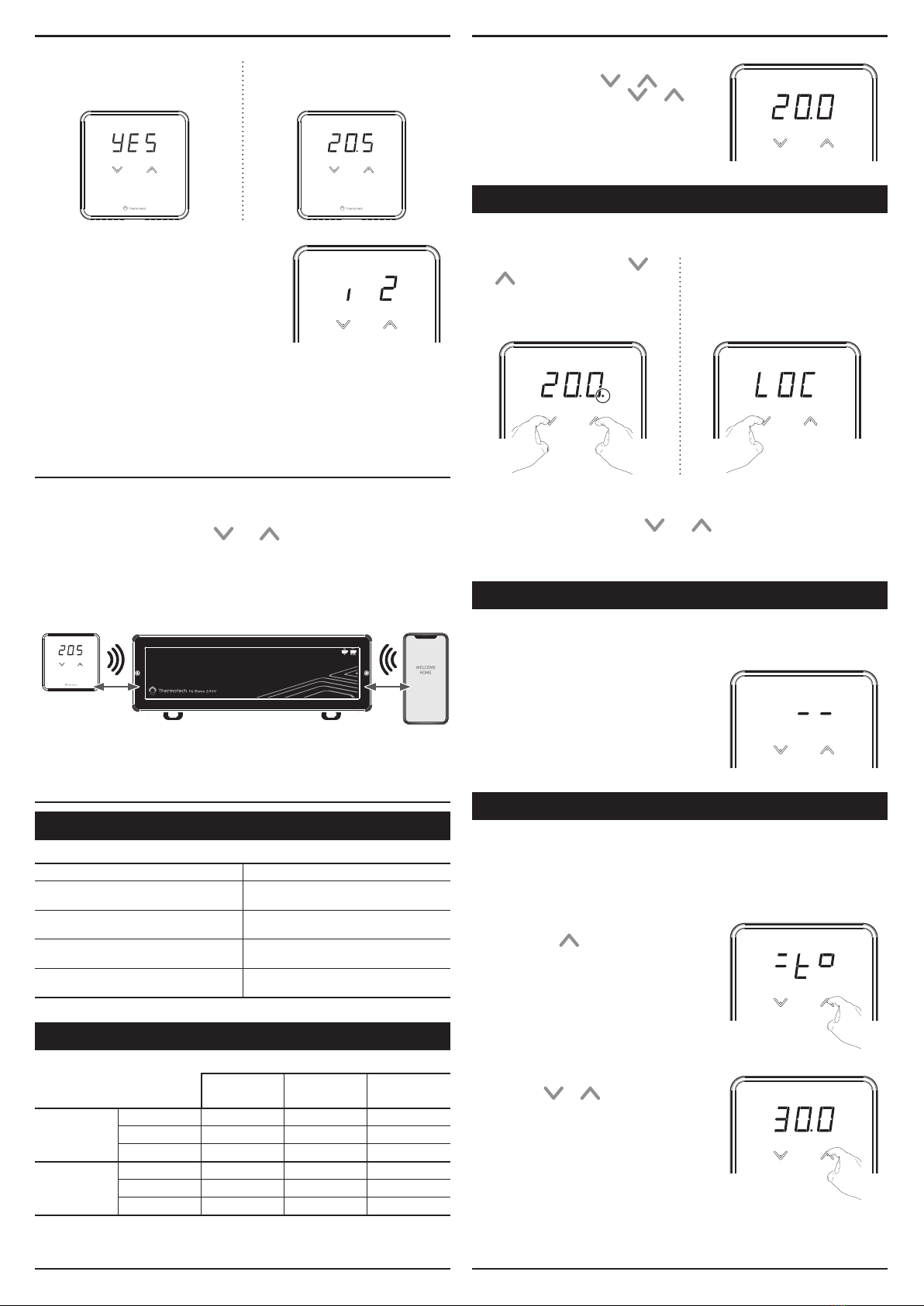
RADIO PAIRING/UNPAIRING
IMPORTANT: Sensitive touch calibration is automatically done after battery
installation or replacement and the front cover has been closed. To do this, put
the front housing back in place, then the thermostat start the calibration, screen
display a countdown. Do not touch the up & down button during the process
until screen turns o and back on.
3- Launch the Radio pairing
When this screen appears, release
the buttons. The pairing process
starts (movement of the display).
4- Launch the pairing on the appli-
cation
Go on your mobile application to
launch the radio pairing and follow
the instructions on the screen.
1- Activate thermostat
Short press on the screen with your
hand.
2- Access to Radio pairing
From main screen, press &
simultaneously (> 5 seconds).
The LOC screen will appear, hold
down the and buttons until
the pairing screen appears.
1 sec.
INSTALLING BATTERIES
2- Remove the front housing from the
thermostat.
1- Press on the clip with a nger
or a at screw driver under the
thermostat.
3- Insert the 2 supplied batteries. Note
the correct polarity when inserting the
batteries.
INSTALLATION
Recommended locations for your thermostat.
To ensure that your thermostat provides accurate readings and controls
eectively, it must be installed approximately 1.5 m above oor level on an inside
wall, away from direct sunshine and any other sources of heat or cold such as
radiators, cold draughts, etc.
Important: The thermostat measures the temperature of the place where it is
installed. It does not take into account the temperature dierences that may exist
between dierent locations in the house if the temperature is not uniform.
• Radio pairing: linking the thermostat to the control unit
and mobile application
1- After installing the batteries, secure
the wall plate with the two screws
provided using the horizontal holes.
The radio room thermostat is xed on the wall with the rear housing of the
product.
MOUNTING OF WALL MOUTING PLATE
2- Replace the front housing of the
thermostat on the wall mounting
plate.
3- Thermostat secures itself by clos-
ing completely the front cover and
hearing "Click".
Inside front cover
Marquage TT caché
Click!
3
RF LORA
869.85MHZ BLE
IQ Room IQ Base IQ Home
GENERAL INFORMATION
1- Before setting up your product, please download and launch the mobile
application to follow the instructions.
2- To save a changed value press and simultanously.
3- Two fast ashes means the value is saved.
4- A ashing value means that the value can be changed (a changed value will
automatically be saved within 4 seconds).
• Thermostat identication
If several thermostats are associated with the
control unit, you can easily locate them. To do
this, start identication from the mobile appli-
cation, in the “control unit parameters” section.
Then the corresponding number(s) will be dis-
played on the thermostat(s). In the exemple: i
(identication) 2 = thermostat number 2.
• Radio unpairing
To cancel the radio pairing between the thermostat, the control unit and the mo-
bile application, see the advanced settings page 4, Radio unpairing section.
6- After 4 seconds back to the main
screen. The ambient temperature
appears.
5- Radio pairing complete
YES appears on the display when
the pairing process is complete.
OPERATING
LED STATUS
Wireless communication LED is blinking fast
Heat demand LED is xed ON, only when the
display is on
Low battery detection LED is blinking: Double blink every 5
minutes from 7:00am to 9:00pm
Leakage sensor detection given by
UFH
LED is blinking: Double blink every 5
minutes from 7:00am to 9:00pm
T° sensor failure detection LED is blinking: Double blink every 5
minutes from 7:00am to 9:00pm
TEMPERATURE SETTING
Comfort Eco Frost
protection
Heating
mode
Default 20°C 16,5°C 12°C
Min. 7°C 5°C 5°C
Max. 30°C 22°C 20°C
Cooling
mode
Default 26°C 28°C NC
Min. 7°C 8°C NC
Max. 30°C 38°C NC
To set the setting temperature, from main
screen, press shortly on or but-
tons and then press again on or
buttons until the desired temperature is
reached.
CHILD LOCK
STANDBY MODE
• Keypad unlock
To unlock the keypad, press the and buttons and hold them for 3 sec-
onds again. OFF (deactivation) appear briey on the display and the dot disap-
pear, the keypad is unlocked.
• Keypad lock
To lock the keypad, press the
and buttons and hold them for
3 seconds. LOC(lock)andOn
(activation) appear briey on the
display and a dot appears after the
last digit. The keypad is locked.
If a button is pressed, LOC appear on
the display for 2 seconds to indicate
that the keyboard is locked and that
the temperature cannot be modied.
3 sec.
The system can be put on heating standby mode via the mobile application.
In this mode, it will operate at a temperature
of 7°C and -- will appear on the display(s)
of the thermostat(s). No action will be possi-
ble on the thermostat(s) until the system is
turned back on via the mobile application.
MAXIMUM TEMPERATURE SETTING
Locking of the setting range using a maximum limit, preventing the setting tem-
perature from being raised above the setting temperature.
The maximum setting is preset to 30°C. You can adjust from 5°C to 30°C in heat-
ing mode, and from 7°C to 38°C in cooling mode by steps of 1°C.
1- To access the maximum temperature
setting, press button during 3 seconds
minimum.
3 sec.
2- To change the maximum temperature set-
ting, press or . The setting is active
after a few seconds.
The temperatures are ajustable by intervals of 0.5°C.

4
CONTROLLER OUTPUT IDENTIFICATION
RADIO UNPAIRING
MINIMUM TEMPERATURE SETTING
Locking of the setting range using a minimum limit, preventing the setting tem-
perature from being lowered below it.
The minimum setting is preset to 5°C. You can adjust from 5°C to 30°C in heating
mode and from 7°C to 38°C in cooling mode by steps of 1°C.
ADVANCED SETTINGS
1- You can easily identify which control unit
output(s) are assigned to each thermostat.
To do this, press from radio unparing
display. rFIappear.
2- Press and simultaneously to enter to the controller output identica-
tion. The associated channel number will appear on the display.
If there is no channel associated to the thermostat, -- will appear.
To access advanced settings, press
simultaneously and at least 10
seconds.
The advanced setting display will appear:
SEt.
Radio unpairing Controller output
identication Temperature compensation
Simultaneous long
press 10 sec.
TEMPERATURE CALIBRATION
To modify the measured temperature correction value, proceed as follow:
In which cases? If the temperature measured in a room (measured by a reliable
thermometer) is dierent of at least 1 or 2°C compared to the setting temperature
of the room thermostat.
The calibration adjusts the temperature measured by the ambient temperature
sensor to compensate for a deviation from +5°C to -5°C by increments of 0.1°C.
IMPORTANT: Before carrying out the calibration it is recommended to wait
for 4h after a setting temperature modication to insure that the ambient
temperature is stabilised.
2- OSt appears on the display, press
and simultaneously to enter
temperature compensation setting.
1- Press from controller output identication
display.
4- Exit by pressing simultaneously on and or wait 4 seconds.
3- If multiple channels are associated to the
thermostat, press or to see the
other associated channels.
3 sec.
1- To access the minimum temper-
ature setting, press button
during 3 seconds minimum.
2- To change the minimum tempera-
ture setting, press or .
The setting is active after a few
seconds.
2- Access to advanced settings
From main screen, press & simulta-
neously (>10 seconds).
SEt will appear on the display.
3- Access to unpairing setting
1Press , UnP (unpair) will appear on the display.
2Then press & simultaneously to start the unpairing process,
will appear on the display.
1 2
4- Radio unpairing complete
YES
appears on the display when
the pairing process is complete.
5- After 4 seconds back to the main
screen.
1- Activate thermostat
Short press on the screen with your hand.
Short
press
10 sec.
Important: The thermostat is no longer linked to the control unit or the mobile
application, so it will no longer be able to execute their orders.

5
4- There are two possibilities:
5- The setting is active a few seconds and the thermostat will return to the main
screen.
3- The display indicates to you the
measured temperature correction value
(which is 0 by default).
4.1- If the room temperature dier-
ence is negative, example:
Setting temperature (what you
want) = 20°C.
Ambient temperature (what you
read on a reliable thermometer)=
18°C.
Dierence mesured = - 2°C.
Decrease the temperature measured
by the ambient temperature sensor by
2°C by pressing button.
4.2- If the room temperature dier-
ence is positive, example:
Setting temperature (what you want) =
19°C.
Ambient temperature (what you read
on a reliable thermometer)= 20°C.
Dierence mesured = +1°C.
Increase the temperature measured
by the ambient temperature sensor by
1°C by pressing button.
ECO REDUCTION SETTING
EXPERT SETTINGS
3- The setting is active after a few seconds and the thermostat will return to the
main screen.
1- To access Eco reduction setting, from
main screen, press for 12 seconds
minimum.
ECO will appears shortly.
12 sec.
2- Press on and buttons to increase
or decrease the Eco reduction level.
The Eco mode reduction setting is preset to -3.5°C. You can adjust from 0°C to
-5°C by step of 0.5°C.
ANTIFREEZE SETTING TEMPERATURE
(AVAILABLE IN HEATING MODE ONLY)
1- To access antifreeze temperature setting,
from main screen, press for 12 sec-
onds minimum.
AF (Anti-Frost) will appears shortly.
12 sec.
The Antifreeze temperature setting is preset to 12°C. You can adjust from 5°C to
20°C by steps of 1°C.
3- The setting is active after a few seconds and the thermostat will return to the
main screen.
2- Press on or buttons to increase
or decrease the frost protection temper-
ature.
Display does not appear on thermostat.
- Check batteries.
- Replace the 2 batteries. Only use alkaline AAA (LR3) batteries.
Do not use rechargeable batteries.
The heating does not turn on or o.
- Your room thermostat may have been set up close to a source of heat or on
a cold wall – put it in a recommended location (see the “Installing” section on
page 2 for these locations).
- Check that the communication works between the thermostat and the control
unit.
The room temperature is not high enough:
- Check the active desired temperature and increase it if needed (see page 3).
The system is not heating but heating demand LED is on:
- If indicator light is on but the system remains cold, then you should contact
your installer.
The thermostat does not regulate properly.
- Check if the device controlled by the room thermostat is connected correctly,
call a qualied installer.
If the problem persists, contact your installer.
TROUBLESHOOTING
Error message Description What to do?
Pairing failed Reset your thermostat and
process to pairing again
Water Leakage detection
has occurred. Please
check your installation
near the central unit and
manifold.
Check your installation near
the central control unit and
the manifold
Temperature sensor open
circuit Change your thermostat
Temperature sensor short
circuit Change your thermostat
Thermostat batteries are
almost empty, please
replace the batteries
Change the batteries of
your thermostat
Radio communication is
lost
Try to activate your thermo-
stat again. If the message
reappears, check that your
control unit is switched on,
then move the thermostat
closer to the control unit. If
the problem persists, con-
tact the After Sales Service.

6
www.thermotech.se
Spårvägen 8, Umeå
S-90131 Sweden
0620-68 33 30
PRODUCTS CODES
- Power supply: batteries, 2 x 1.5VDC AAA / LR03 Alkaline only.
- Protection: class III, IP20.
Radio:
- Frequency range: 869,725- 869, 975Mhz.
- Radiated power: <10dbm.
- Receiver category 2.
- SAR: radiated power is under 13dbm.
Environment:
- Operation temperature: 0°C to +40°C.
- Storage temperature: from -20°C to +70°C.
- Humidity: 85% at +25°C (without condensation)
- Protection rating: IP20.
Manufacturer: THERMOTECH -Spårvägen 8, Umeå - S-90131 Sweden -
Website: www.thermotech.se
TECHNICAL SPECIFICATIONS
The symbol , axed on the product indicates that you must dispose of it at
the end of its useful life at a special recycling point, in accordance with European
Directive WEEE 2012/19/EU. If you are replacing it, you can also return it to the
retailer from which you buy the replacement equipment. Thus, it is not ordinary
household waste. Recycling products enables us to protect the environment and
to use less natural resources.
SIMPLIFIED EU DECLARATION OF CONFORMITY :
Hereby, Thermotech declares that the radio equipment type,
Radio room thermostat IQ Room (Ref: 67940 & 67942), is in
compliance with directives
The full text of the EU declaration of conformity is available at the following
internet address: https://www.thermotech.se/dokumentation/
2014/53/EU and 2011/65/EU.
Product codes Photos Descriptions
67940 IQ Room, radio room
thermostat, white
67942 IQ Room, radio room
thermostat, black
Compatible with the following products (sold separately):
Wireless control unit for underoor heating/cooling
Product codes Photos Description
67912
IQ Base
Wireless control unit (24V
AC)
67914
IQ Base
Wireless control unit (230V
AC)
This manual suits for next models
1
Table of contents
Other Thermotech Thermostat manuals


Popular Thermostat manuals by other brands


EUROSTER
EUROSTER 2006TXRXG Installation and operation manual

OCSTAT
OCSTAT S701 instructions

Elbro AG
Elbro AG smartButler SMSB121TH Instructions for use

DIVERSITECH
DIVERSITECH 675-TS21 instruction manual

nSpire
nSpire Touch WiFi Setup Instruction

Lux Products
Lux Products T20-1141SA Installation and operating instructions