Thern FVC-1000 User manual

Owner’s Manual
For The
FVC-1000
Fire Vent Closure Winch
A8018B-1210
Read this Owner’s Manual
thoroughly before operating
the equipment. Keep it with
the equipment at all times.
Replacements are available
from Thern, Inc., PO Box 347,
Winona, MN 55987,
507-454-2996.
www.thern.com
IMPORTANT: Please record
product information on
page 2. This information is
required when calling the
factory for service.

Owner's Manual for Thern Model FVC-1000 Winchespage 2
A8018B-1210
Two-Year Limited Warranty
Thern, Inc. warrants its products against defects in material or workmanship for two years from the date of purchase
by the original using buyer, or if this date cannot be established, the date the product was sold by Thern, Inc. to the
dealer. To make a claim under this warranty, contact the factory for an RGA number. The product must be returned,
prepaid, directly to Thern, Inc., 5712 Industrial Park Road, Winona, Minnesota 55987. The following information
must accompany the product: the RGA number, the date of purchase, the description of the claimed defect, and a com-
plete explanation of the circumstances involved. If the product is found to be defective, it will be repaired or replaced
free of charge, and Thern, Inc. will reimburse the shipping cost within the contiguous USA.
This warranty does not cover any damage due to accident, misuse, abuse, or negligence. Any alteration, repair or
modification of the product outside the Thern, Inc. factory shall void this warranty. This warranty does not cover any
costs for removal of our product, downtime, or any other incidental or consequential costs or damages resulting from
the claimed defects. This warranty does not cover brake discs, wire rope or other wear components, as their life is
subject to use conditions which vary between applications.
FACTORYAUTHORIZED REPAIR OR REPLACEMENT AS PROVIDED UNDER THIS WARRANTY IS THE
EXCLUSIVE REMEDY TO THE CONSUMER. THERN, INC. SHALL NOT BE LIABLE FOR ANY INCIDENTAL
OR CONSEQUENTIAL DAMAGES FOR BREACH OF ANYEXPRESS OR IMPLIED WARRANTY ON THIS
PRODUCT. EXCEPT TO THE EXTENT PROHIBITED BYAPPLICABLE LAW, ANY IMPLIED WARRANTY
OF MERCHANTABILITY OR FITNESS FOR A PARTICULAR PURPOSE ON THIS PRODUCT IS LIMITED IN
DURATION TO THE DURATION OF THIS WARRANTY.
Some states do not allow the exclusion or limitation of incidental or consequential damages, or allow limitations on
how long an implied warranty lasts, so the above limitation or exclusion may not apply to you. This warranty gives
you specific legal rights, and you may also have other rights which vary from state to state.
Note: Thern, Inc. reserves the right to change the design or discontinue the production of any product without
prior notice.
About This Manual
The Occupational Safety and Health Act of 1970 states that it is the employer’s
responsibility to provide a workplace free of hazard. To this end, all equipment
should be installed, operated, and maintained in compliance with applicable trade,
industrial, federal, state, and local regulations. It is the equipment owner's respon-
sibility to obtain copies of these regulations and to determine the suitability of the
equipment to its intended use.
This Owner’s Manual, and warning labels attached to the equipment, are to serve
as guidelines for hazard-free installation, operation, and maintenance. They should
not be understood to prepare you for every possible situation.
The information contained in this manual is applicable only to the Thern Model
FVC-1000 Winches. Do not use this manual as a source of information for any
other equipment.
The following symbols are used for emphasis throughout this manual:
Failure to follow ‘WARNING!’ instructions may result in equipment damage,
property damage, and/or serious personal injury.
Failure to follow ‘CAUTION!’instructions may result in equipment damage,
property damage, and/or minor personal injury.
Important!
Failure to follow ‘important!’instructions may result in poor performance of
the equipment.
Please record the following:
Date Purchased:
Model Number:
Serial Number:
This information is required when
calling the factory for service.

Owner's Manual for Thern Model FVC-1000 Winches page 3
A8018B-1210
Suggestions for Safe Operation
DO the following:
Read and comply with the guidelines set forth in this Owner’s Manual. Keep
this manual, and all labels attached to the winch, readable and with the equip-
ment at all times. Contact Thern, Inc. for replacements.
Check lubrication before use.
Install the wire rope securely to the winch drum.
Keep at least 4 wraps of wire rope wound on the drum at all times, to serve as
anchor wraps. With less than 4 wraps on the drum the wire rope could come
loose, causing the load to escape.
Keep hands away from the drum, gears, wire rope, and other moving parts of
the equipment.
Keep all unnecessary personnel away from the winch while in operation. Keep
out of the path of the load, and out of the path of a broken wire rope that
might snap back and cause injury.
DO NOT do the following:
This product designed for closing and releasing fire vent doors. Do not use
this product for any other purpose.
Do not use more than one winch to operate a single fire vent.
Do not use damaged or malfunctioning equipment. To do so could result in
failure of the equipment.
Do not modify the equipment in any way. To do so could cause equipment
failure.
Do not wrap the wire rope around building structures or other objects. This
damages the wire rope and could cause the load to escape. Use approved rig-
ging connectors to secure the wire rope to the load.
Do not operate the winch with guards removed or improperly installed.
Do not divert your attention from the operation. Stay alert to the possibility of
accidents, and try to prevent them from happening.

Owner's Manual for Thern Model FVC-1000 Winchespage 4
A8018B-1210
Important!
• Inspect the winch immediately
following installation according
to the Instructions for Periodic
Inspection. This will give you
a record of the condition of the
winch with which to compare
future inspections.
• A qualified professional should
inspect or design the founda-
tion to insure that it will provide
adequate support.
• Locate the winch so it will be
visible during the entire operation.
1.1 Installing the Winch
Do not install the winch in an area defined as hazardous by the National Elec-
tric Code, unless installation in such an area has been thoroughly approved.
Do not install the winch near corrosive chemicals, flammable materials, ex-
plosives, or other elements that may damage the winch or injure the operator.
Adequately protect the winch and the operator from such elements.
Position the winch so the operator can stand clear of the load, and out of the
path of a broken wire rope that could snap back and cause injury.
Attach the winch to a rigid and level foundation that will support the winch
and its load under all load conditions, including shock loading.
1.1.1 CONSULT APPLICABLE CODES AND REGULATIONS for specific rules
on installing the equipment.
1.1.2 LOCATE THE WINCH in an area clear of traffic and other obstacles. Make
sure the winch is accessible for maintenance and operation.
1.1.3 MAINTAIN A FLEET ANGLE up to 1 1/2 degrees for smooth drums and 2
degrees for grooved drums. The proper fleet angle minimizes wire rope dam-
age by helping the wire rope wind uniformly onto the drum. See Figure 1.
1.1.4 FASTEN THE WINCH securely to the wall or a horizontal support structure.
Use four 3/8 inch capscrews grade 5 or better to install the winch. See Figure 2.
TO COMPLY WITH LOCAL CODES, CONTACTAQUALIFIED PROFES-
SIONALTO OBTAIN PROPER STRUCTURE OR FOUNDATION SPECI-
FICATIONS FOR THE MOUNTING OFTHERN PRODUCTS.
Important!
• Use a sheave or roller guide to
direct the wire rope to the drum
whenever possible.
•
Install sheaves and other equip-
ment so they will remain fixed
under all load conditions. Fol-
low the recommendations of the
equipment manufacturer.
• Use sheaves of proper diameter to
minimize wear on the wire rope.
Follow the recommendations of
the sheave manufacturer.
smooth drum
1/2 to 1-1/2 degrees
distance required to maintain fleet angle
center
line
fixed sheave or
attachment
point
Figure 1 – Maintaining the Fleet Angle

Owner's Manual for Thern Model FVC-1000 Winches page 5
A8018B-1210
Figure 2 – Installing the Winch
wall mount
base mount

Owner's Manual for Thern Model FVC-1000 Winchespage 6
A8018B-1210
1.2 Installing the Wire Rope
Install the wire rope so it is wound correctly as shown or the winch and brake
will not work properly, and could allow the load to escape.
Install the wire rope securely to the winch drum.Apoorly secured wire rope
could come loose from its anchor and allow the load to escape.
1.2.1 PURCHASE THE PROPER WIRE ROPE for your application. Keep the
following in mind when selecting a wire rope. Contact a reputable wire rope
supplier for help.
a BREAKING STRENGTH of new wire rope should be at least 5 times great-
er than the largest load placed on the winch. This is a minimum value and
will vary depending on installation and application conditions.
b WIRE ROPE LAY must agree with the winding direction of the drum to help
insure proper winding.
c WE RECOMMEND 7 x 19 galvanized aircraft cable.
1.2.2 INSTALL THE WIRE ROPE using the flange clip anchor. See Figure 3.
a WIND THE END OF THE WIRE ROPE around the drum in the proper
direction as shown, or the winch will not operate correctly.
b PULL THE END OF THE WIRE ROPE through the hole in the flange.
c INSERT THE CARRIAGE BOLT, loop the wire rope around the bolt, and
install the clip so the wire rope is held by the curves of the clip.
d INSTALL THE JAM NUT and tighten it until the wire rope is flattened
against the drum flange.
1.2.3 TURN THE HANDLE CLOCKWISE to wind wire rope onto the drum. If
wire rope unwinds from the drum when the handle is rotated clockwise, the
wire rope is installed incorrectly. Install the wire rope correctly before
continuing.
1.2.4 WIND FOUR FULL WRAPS of wire rope onto the drum by operating the
winch while holding the wire rope taught. These wraps serve as anchor
wraps. Keep the number of anchor wraps to a minimum. Excessive
anchor wraps may recoil off the drum when the fire vent is released.
Important!
• Use wire rope and other rigging
equipment rated for the size of the
largest load you will be moving.
• Do not drag the wire rope
through dirt or debris that could
cause damage, or poor operation.
• Always wear protective clothing
when handling wire rope.
Figure 3 – Flange Clip
Anchor
wind the wire rope
onto the drum in
the direction shown
or the winch will not
operate correctly
typical installation shown
right lay - underwound
drum end view

Owner's Manual for Thern Model FVC-1000 Winches page 7
A8018B-1210
2.1 General Theory of Operation
2.1.1 THE FORCE REQUIRED to seal the fire vent must not exceed the load
rating of the winch.
2.1.2 THIS EQUIPMENT CAN develop forces that will exceed the load rating.
Inspect the equipment regularly for damage according to the instructions
contained in this manual.
2.1.3 PERFORMANCE RATINGS of the equipment are affected by the amount of
wire rope wound on the drum and the way in which it is wound.
a DRUM CAPACITY depends on how tightly and evenly the wire rope is
wound on the drum. Actual drum capacities are usually 25-30% less than
values shown in performance tables, due to loose winding and overlapping.
b HANDLE FORCE REQUIRED the load increases with each additional layer
of wire rope wound onto the drum. Line speed also increases with each ad-
ditional layer of wire rope wound onto the drum.
c LOAD RATING represents the maximum pull that can be placed on new
equipment. Load ratings are assigned values for specific amounts of load
travel or wire rope accumulation. The load rating decreases as layers of wire
rope accumulate on the drum.
2.1.4 DUTY RATINGS refer to the type of use the equipment is subject to. Con-
sider the following when determining duty rating.
a ENVIRONMENT: harsh environments include hot, cold, dirty, wet, corro-
sive, or explosive surroundings. Protect the equipment from harsh envi-
ronments when possible.
b MAINTENANCE: poor maintenance, meaning poor cleaning, lubrication,
or inspection, leads to poor operation and possible damage of the equipment.
Minimize poor maintenance by carefully following the instructions con-
tained in this manual.
c LOADING: severe loading includes shock loading and moving loads that
exceed the load rating of the equipment. Avoid shock loads, and do not
exceed the load rating of the equipment.
d
FREQUENCY OF OPERATION: frequent operation increases wear and short-
ens the life span of gears, bearings, and other components. Increase mainte-
nance of the equipment if used frequently.
CONTACT THE FACTORY FOR MORE INFORMATION.
Important!
• Limit nonuniform winding by
keeping tension on the wire rope
and by maintaining the proper
fleet angle.
• It is your responsibility to detect
and account for different fac-
tors affecting the condition and
performance of the equipment.

Owner's Manual for Thern Model FVC-1000 Winchespage 8
A8018B-1210
2.2 Preparing for Operation
2.2.1 CONSIDER THE OPERATION. Do not begin until you are sure you can
perform the entire operation without hazard.
2.2.2 INSPECTALL COMPONENTS of the system.
a INSPECT THE WINCH and other equipment according to the Instructions
for Frequent Inspection.
b OPERATORS must be in good health, alert, and thoroughly trained in oper-
ating the equipment, and properly clothed (no loose clothing, hard hat and
safety glasses required).
c THE FIRE VENT must be clear of other objects and free to open.
2.2.3 KNOW YOUR LOAD and make sure you do not exceed the load rating of
the winch or other equipment in the system.
2.2.4 REPLACE NYLON CABLE TIE with customer supplied fusible link. See
item 49 on page 17.
2.3 Close and Set the Fire Vent
Handle may spin when released. Do not release handle unless fire event is held
securely by ratchet or brake.
Make sure the ratchet is in the ratchet engaged position before adjusting the
band brake.
2.3.1 ENGAGE THE RATCHET by moving the ratchet spring to the RATCHET
ENGAGED position.
2.3.2 INSTALL THE HANDLE by sliding the handle onto the input shaft and
securing it in place with the lynch pin.
2.3.3 CLOSE THE FIRE VENT by rotating the handle clockwise to wind wire
rope onto the winch drum. If the wire rope unwinds from the drum when the
handle is rotated clockwise, the wire rope is installed incorrectly. Install the
wire rope correctly before continuing.
2.3.4 OBSERVE THE WIRE ROPE as it winds onto the drum. If it becomes
loose, uneven, or overlapped, stop the operation and rewind the wire rope
before continuing. Continued operation with overlapped or uneven wire
rope can damage the wire rope and shorten its life.
2.3.5 INSTALL THE ETL (ELECTRO-THERMAL LINK) when the fire vent is
fully closed and sealed. The ETL is installed between the guard cover and
the spring inside the access panel.
2.3.6 ADJUST BRAKE TENSION by loosening or tightening the band brake
adjusted nut. Adjust the band brake to create 4-4.318 inches of tension in the
spring, measured from hook to hook.
Important!
• Obey a stop signal from anyone.
• Maintain tension on the wire
rope to keep it tightly and evenly
wound on the drum.
• If the fire vent is not visible
during operation, get help from
another person.
• Remove the winch handle when
the winch is not in use, to help
avoid unauthorized use.

Owner's Manual for Thern Model FVC-1000 Winches page 9
A8018B-1210
2.3.7 DISENGAGE THE RATCHET by moving the ratchet spring to the
RATCHET DISENGAGED position and turning the handle clockwise
slowly until the ratchet disengages completely. If you feel pressure in the
handle, do not let it go. Do not let go of the handle until the fire vent is
held securely by the band brake.
2.3.8 READJUST BRAKE TENSION as necessary by repeating the above steps
until the fire vent is held securely closed. Always engage the ratchet before
adjusting the band brake.
2.3.9 REMOVE THE HANDLE and slide it into the slot in the guard for storage.
Make sure the ratchet is in the RATCHET DISENGAGED position.
2.4 Testing the Fire Vent
Remove the handle before testing fire vent operation. The handle will spin if
attached to the winch.
Keep away from the spinning drum and input shaft when fire vent is released
during testing.
2.4.1 MAKE SURE THE HANDLE is removed from the winch or stored in the
guard frame.
2.4.2 MAKE SURE THE RATCHET is in the RATCHET DISENGAGED posi-
tion.
2.4.3
OPEN THE ACCESS PANEL on the back of the winch by removing the
lynch pin and pulling the panel down.
2.4.4 RELEASE THE FIRE VENT by standing clear of the winch and pulling
down on the test handle to release tension in the band brake. Keep away
from the spinning drum and input shaft during the test operation.
2.4.5
VERIFY THE FIRE VENT OPENS FULLY when the test arm is pushed
down and the brake is released. If the fire vent fails to open, engage the ratch-
et and loosen the band brake by turning the adjusting nut counterclockwise
1/4 turn. Continue to adjust the brake until the fire vent springs open properly
when the brake is released with the test arm.
2.4.6 RESET THE FIRE VENT by following the instructions to CLOSE and SET
the fire vent.

Owner's Manual for Thern Model FVC-1000 Winchespage 10
A8018B-1210
3.1 Cleaning the Winch
Clean the winch to remove dirt and help prevent rust and corrosion.
3.1.1 CLEAN THE WINCH every 6 months or whenever it is dirty.
a WIPE ALL EQUIPMENT to remove dirt and grease.
b LEAVE A LIGHT FILM of oil on all surfaces to protect them against rust
and corrosion.
c WIPE OFF excessive amounts of oil to avoid the accumulation of dirt.
3.1.2 REMOVE ALL UNNECESSARY OBJECTS from the area surrounding the
winch.
3.2 Lubricating the Winch
3.2.1 CONSULT MANUFACTURER'S RECOMMENDATIONS for specific
information on lubricating the wire rope and other equipment.
3.2.2
LUBRICATE WINCH BEARINGS AND SHAFTS at least every 6 months.
a
APPLY 2 TO 3 DROPS of SAE 30 non-detergent oil to bearings and shafts at
all friction points.
b ROTATE THE DRUM several times to allow the oil to penetrate, and wipe
off excess oil to avoid accumulation of dirt.
3.2.3 LUBRICATE WINCH GEARS at least every 10 hours of operation
.
a
APPLYA LIGHT FILM of open gear lubricant to the gear teeth on all gears.
b USE SPRAYON 201 or equivalent open gear lube. For dirty conditions use a
dry lubricant such as dry graphite or Moly.
3.2.4 LUBRICATE THE WIRE ROPE by following the wire rope manufacturer's
recommendations.
Important!
• Make sure lubricant has a tem-
perature rating appropriate for
the ambient temperatures of the
operation.
Important!
Increase the frequency of mainte-
nance procedures if the winch is:
• Operated frequently.
• Used to move heavy loads.
• Operated in wet, dirty, hot, or
cold surroundings.

Owner's Manual for Thern Model FVC-1000 Winches page 11
A8018B-1210
3.3 Inspecting the Equipment
Do not use damaged or malfunctioning equipment. Place an “OUT OF ORDER”
sign on the winch. Do not use the winch until the sign is removed by a qualified
maintenance person who has completely corrected the problem.
3.4.1 CONSULT APPLICABLE CODES AND REGULATIONS for specific rules
on inspecting the winch and other equipment.
3.4.2 CONSULT MANUFACTURER’S RECOMMENDATIONS for information
on inspecting the wire rope and other equipment.
3.4.3 Instructions for Frequent Inspection
a VISUALLY INSPECT the entire winch and all other equipment involved in
the operation.
• Check all equipment for cracks, dents, bending, rust, wear, corrosion and
other damage.
• Make sure the wire rope is installed correctly and anchored securely to
the drum.
• Make sure the winch is properly lubricated.
• Make sure mounting fasteners are tightened securely.
• Make sure the foundation is in good condition, and capable of supporting
the winch under all load conditions.
• Listen for unusual noises, and look for signs of damage as you operate the
winch.
Completely correct all problems before continuing. Use the Troubleshooting
Chart to help determine the cause of certain problems. See Table 2.
Important!
•
Start an inspection program as soon
as you put the winch into use.
• Appoint a qualified person to be
responsible for regularly inspect-
ing the equipment.
• Keep written records of inspec-
tion. This allows comparison with
comments from previous inspec-
tions so you can see changes in
condition or performance.

Owner's Manual for Thern Model FVC-1000 Winchespage 12
A8018B-1210
3.4.4 Instructions for Periodic Inspection
a OPEN THE FIRE VENT to release tension from the winch and wire rope by
following the procedure for testing the fire vent.
b VISUALLY INSPECT the winch and all other equipment.
• Check the finish for wear, flaking, or other damage.
• Check all equipment for cracks, dents, bending, rust, wear, corrosion
and other damage. If the winch was overloaded, or if you notice cracks
or other signs of overloading and damage, consider using magnetic or
chemical crack detecting procedures. DO NOT CONTINUE TO USE
DAMAGED OR OVERLOADED EQUIPMENT OR WIRE ROPE.
• Check all fasteners for stripped threads, wear, bending, and other damage.
• Check the foundation for cracks, corrosion or other damage.
• Make sure the winch is lubricated properly.
• Make sure all labels and plates are readable, firmly attached, free of dam-
age and clean. Replacements are available from the factory.
• Check the entire length of wire rope for bent wires, crushed areas, broken
or cut wires, corrosion, and other damage. Carefully inspect areas that
pass over sheaves or through roller guides.
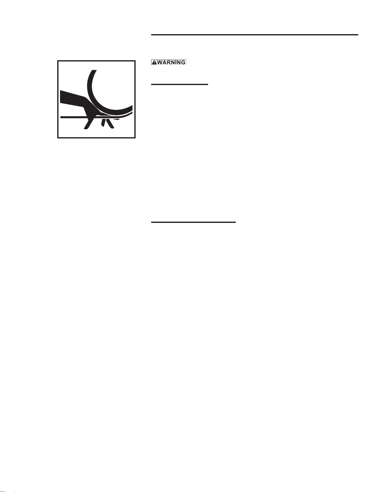
• Note the location and concentration of broken wires. Replace wire rope if
more than 6 wires are broken in one lay, or more than 3 wires are broken
in one strand in one lay. See Figure 4.
• Make sure connecting devices are securely attached to the wire rope, and
the wire rope where they are attached is not frayed, corroded, broken, or
otherwise damaged.
• Make sure the wire rope is securely anchored to the drum and inspect the
flange clip for signs of wear or distortion.
• Make sure the ratchet engages and disengages completely.
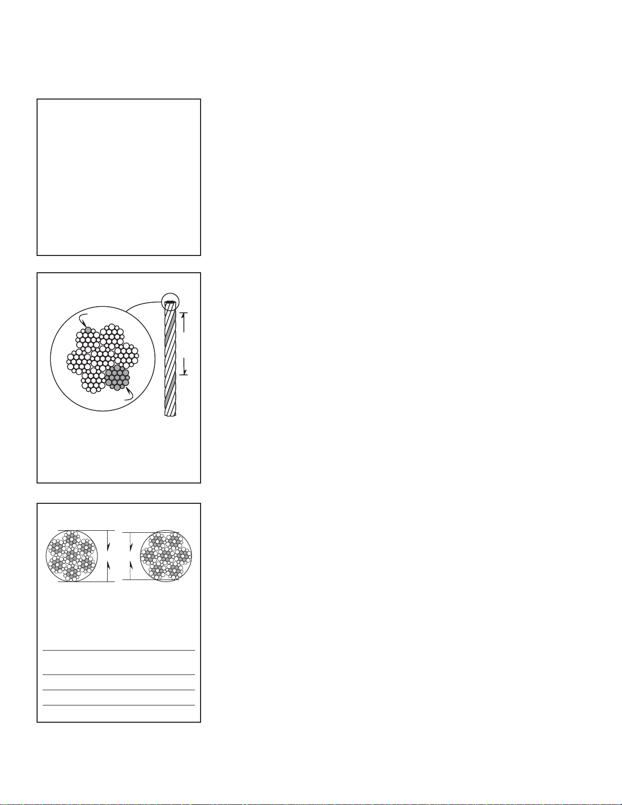
• Measure the diameter of the wire rope, especially in areas where wear
is noticeable. Replace the wire rope if the diameter measures below the
minimum diameter at any point. See Figure 5.
• Check for excessive drum movement indicating worn or loose gears,
bearings, or shafts.
• Disassemble the winch if necessary. Inspect gears, bearings, spring pins,
and shafts for wear, corrosion, distortion, and other damage.
c MONITOR WINCH PERFORMANCE as winch is operated.
• Listen for unusual noises, and look for signs of damage as you operate the winch.
• Make sure the wire rope winds evenly and tightly onto the drum. If it is
loose or uneven, rewind it before continuing.
• Observe the rotating drum; look for signs of loose or misaligned bearings.
Completely correct all problems before continuing. Use the troubleshooting
chart to help determine the cause of certain problems. See Table 2.
Perform periodic inspections:
• Every 6 months.
• Whenever you return the winch
to service from storage.
• Whenever you notice damage
or poor operation in a frequent
inspection.
• Whenever you have, or think you
may have, overloaded or shock
loaded the winch.
wire
strand
one
lay
Figure 4 – Broken Wires
Wire rope assembly must be re-
placed if more than 6 wires are
broken in one lay, or if more than
3 wires are broken in one strand
in one lay.
diameter
correct incorrect
Figure 5 – Rope Diameter
The wire rope assembly must be
replaced if the diameter measures
less than the minimum diameter at
any point.
wire rope
diameter minimum diameter
1/8 in 7/64 in (.1094 in)
3/16 in 11/64 in (.1719 in)
1/4 in 15/64 in (.2344 in)

Owner's Manual for Thern Model FVC-1000 Winches page 13
A8018B-1210
Table 1 – Inspection Checklist
damages problems
general finish weathered, flaking, otherwise damaged winch jerks or hesitates during operation
parts cracked, bent, rusted, worn, otherwise damaged unusual noises, other signs of malfunction
fasteners stripped threads, bent, worn, otherwise damaged loose, not tightened to the proper torque
gears excessively worn ,cracked, corroded, otherwise damaged loose or improperly lubricated
brake brake corroded, cracked, worn, otherwise damaged brake does not operate properly
drum anchor hole worn, distorted, otherwise damaged excessive movement or backlash
wire rope bent, crushed, otherwise damaged wire rope loosely or unevenly wound
broken wires, see Figure 4
replace if more than 6 wires in one lay, number per strand =
or 3 wires in one strand in one lay, are broken number per lay =
diameter reduced, see Figure 5
replace if diameter is excessively worn diameter =
end connections corroded, rusted, worn, otherwise damaged not securely attached
labels and plates dirty, illegible, otherwise damaged loosely attached or missing
comments
authorized signature date
checked boxes indicate damage or problem in need of repair
Table 2 – Troubleshooting Chart
Contact the factory for detailed instructions on re-sealing the gearbox if you are required to disassemble the
gearbox for any reason. Disassembly of the gearbox before contacting Thern, Inc. voids all warranties.
problem cause correction
handle turns, drum doesn’t turn • loose or broken spring pins or shafts inspect winch and repair as necessary
• loose, stripped or broken gears or keys inspect gears and repair as necessary
handle turns hard or not at all • spring pins loose or broken on winch inspect winch and repair as necessary
• brake band too tight or locked inspect brake, adjust or repair as necessary
• gears or bearings broken or locked inspect and repair as necessary
brake does not operate properly • brake worn or damaged inspect and replace as necessary
• brake hub damaged or broken inspect and repair as necessary
excessively worn gears or bearings • excessive overloading inspect installation and correct as necessary
• poor lubrication of gears or bearings inspect and lubricate as necessary
overheating • operated too long without rest allow to cool
• poor lubrication inspect and lubricate as necessary
• bearing seized up inspect and replace as necessary
unusual noises
high pitched squeak • poor lubrication inspect and lubricate as necessary
grinding noise • contaminated lubrication drain, clean and lubricate the winch
• dirt in winch gears inspect and clean as necessary
• broken gears or bearings inspect and replace as necessary
rattling noise • loose bolts, set screws or other fasteners tighten all bolts and other fasteners

Owner's Manual for Thern Model FVC-1000 Winchespage 14
A8018B-1210
3.4 Repairing the Winch
3.4.1 GET FACTORYAUTHORIZATION for all repairs. Unauthorized repairs
will void the warranty, and may lead to damage or failure of the winch.
3.4.2 REPLACE DAMAGED OR POORLY OPERATING PARTS with Thern
repair parts.
3.4.3 REFINISH AREAS where the paint is worn or flaking. A good finish helps
to protect against corrosion and environmental damage.
a REMOVE THE FINISH from damaged areas, down to the bare metal.
b CLEAN THE AREA thoroughly.
c REPAINT with a high quality primer and finishing coat.
3.4.4 TO ORDER REPAIR PARTS, contact your local dealer. Include the follow-
ing information when ordering:
• model number
• serial number (or code number)
• part number
• date purchased, and from whom
• description of what happened, or what is wrong
• your name and return address
Important!
• It is your responsibility to de-
termine when to replace parts.
When considering whether to
continue using a part or to replace
it, remember that replacing it
is the best way to avoid further
equipment damage.
• Replace spring pins and retaining
rings when you disassemble the
winch for repair or replacement.
• Appoint a qualified person to be
responsible for all repairs to the
equipment.

Owner's Manual for Thern Model FVC-1000 Winches page 15
A8018B-1210
4.1 Transporting the Winch
4.1.1 REMOVE THE BREATHER PLUG(S) and install a sealed oil plug(s) to
prevent the loss of lubrication during shipment.
4.1.2 PACK THE WINCH in an upright position for transport, using the original
packaging materials, if possible.
a FASTEN THE WINCH to a wooden base using lag bolts, to keep it from
moving during transport.
b SEAL THE WINCH in plastic with a desiccant to help protect it from rust,
corrosion, and other damage.
c CONSTRUCT WOODEN SIDES and top to enclose the winch in a solid
protective crate.
d PACK LOOSE PARTS in small boxes or ship separately.
4.1.3 INSPECT THE WINCH according to the Instructions for Periodic Inspection
before installing it in a new location.
4.2 Storing the Winch
4.2.1 LUBRICATE THE WINCH as necessary, and make sure the breather plug(s)
is clean and properly installed. Add a rust preventative for long term storage.
4.2.2 SEAL THE WINCH in plastic with a desiccant to help protect it from rust,
corrosion, and other damage.
4.2.3 STORE THE WINCH upright, in a cool clean place away from corrosive
chemicals and moisture.
4.2.4 ROTATE THE DRUM PERIODICALLY to keep bearing and gear surfaces
from becoming lacquered.
4.2.5 INSPECT THE WINCH according to the Instructions for Periodic Inspection
before installing it for operation.
4.2.6 LUBRICATE THE WINCH PROPERLY prior to operation. See Section 3.3
Lubricating the Winch.
Important!
• Keep a record of what you ship,
and when you send it.

Owner's Manual for Thern Model FVC-1000 Winchespage 16
A8018B-1210
Model FVC-1000 Winches
item description part number qty.
1 FRAME WELDMENT SC4003 1
2 DRUM ASSEMBLY B2365BLK 1
3 DRUM SPACER A1145 1
4 CAPSCR HEXHD .375 X 6.500 A5039 2
5 HEX NUT .375 A3113 3
6 FLANGE BEARING A1003 2
7 COUNTER SHAFT SA5786 1
8 RETAINING RING .625 A4136 1
9 RATCHET PIN SA5785 1
10 FRAME SPACER SC5784 1
11 GUARD BACK SC4074 1
12 GUARD DOOR SC4075 1
13 GUARD FRONT SD3768 1
14 BRAKE HANDLE SC4072 1
15 BRAKE BAND SB5543 1
16 BRAKE DRUM WELDMENT SB5544 1
17 HEX JAM NUT .375 A3330 1
18 WASHER .375 A3939 1
19 GROOVE PIN .188 X 1.125 A4524 1
20 HOOK BOLT A7956 1
21 GEAR GUARD B1066BLK 1
22 GUARD SPACER SC4073 1
23 WARNING LABEL HANDS AWAY A2659 1
24 LYNCH PIN .188 X 1.562 A7693 2
25 FLT WASHER .312 A2924 12
26 HXHEAD CAPSCREW .312 X .750 A3032 6
27 TIE DOWN A1013 1
28 HEX NUT .250SST A3331 1
29 CARIGBOLT .250 X .500 SST A3333 1
30 HXHEAD CAPSCREW .312 X .100 A3028 2
31 HEX NUT NYLK .312 A2927 2
32 WARNING LABEL A8019 1
33 WARNING LABEL REMOVE HANDLE A8026 1
34 MODEL / OPERATING LABEL A8017 1
35 EXTENSION SPRING A7913 1
36 PINION A1008 1
37 GROOVE PIN .188 X 1.375 A4851 1
38 COTTER PIN .156 X 1.00 A3059 1
39 FLAT WASHER .375 A3114 1
40 HANDLE ASSEMBLY B4187 1
41 WARNING LABEL HANDLE A8025 1
42 WINDING DIRECTION LABEL A8029 1
43 WARNING LABEL ADJUST BRAKE A8024 1
44 RATCHET PAWL A1047 1
45 TORSIONAL SPRING B1145 1
46 LABEL DISENGAGED A8028 1
47 LABEL ENGAGED A8027 1
48 S-HOOK 1.00 X .162 A7975 1
49 FUSIBLE LINK (SUPPLIED BY CUSTOMER) - 1
50 SPACER A8111 1

Owner's Manual for Thern Model FVC-1000 Winches page 17
A8018B-1210

Owner's Manual for Thern Model FVC-1000 Winchespage 18
A8018B-1210
Model FVC-1000 Winches
item description part number qty.
1 FRAME WELDMENT SC4003 1
2 DRUM ASSEMBLY B2365BLK 1
3 DRUM SPACER A1145 1
4 CAPSCR HEXHD .375 X 6.500 A5039 2
5 HEX NUT .375 A3113 3
6 FLANGE BEARING A1003 2
7 COUNTER SHAFT SA5786 1
8 RETAINING RING .625 A4136 1
9 RATCHET PIN SA5785 1
10 FRAME SPACER SC5784 1
11 GUARD BACK SC4074 1
12 GUARD DOOR SC4075 1
13 GUARD FRONT SD3768 1
14 BRAKE HANDLE SC4072 1
15 BRAKE BAND SB5543 1
16 BRAKE DRUM WELDMENT SB5544 1
17 HEX JAM NUT .375 A3330 1
18 WASHER .375 A3939 1
19 GROOVE PIN .188 X 1.125 A4524 1
20 HOOK BOLT A7956 1
21 GEAR GUARD B1066BLK 1
22 GUARD SPACER SC4073 1
23 WARNING LABEL HANDS AWAY A2659 1
24 LYNCH PIN .188 X 1.562 A7693 2
25 FLT WASHER .312 A2924 12
26 HXHEAD CAPSCREW .312 X .750 A3032 6
27 TIE DOWN A1013 1
28 HEX NUT .250SST A3331 1
29 CARIGBOLT .250 X .500 SST A3333 1
30 HXHEAD CAPSCREW .312 X .100 A3028 2
31 HEX NUT NYLK .312 A2927 2
32 WARNING LABEL A8019 1
33 WARNING LABEL REMOVE HANDLE A8026 1
34 MODEL / OPERATING LABEL A8017 1
35 EXTENSION SPRING A7913 1
36 PINION A1008 1
37 GROOVE PIN .188 X 1.375 A4851 1
38 COTTER PIN .156 X 1.00 A3059 1
39 FLAT WASHER .375 A3114 1
40 HANDLE ASSEMBLY B4187 1
41 WARNING LABEL HANDLE A8025 1
42 WINDING DIRECTION LABEL A8029 1
43 WARNING LABEL ADJUST BRAKE A8024 1
44 RATCHET PAWL A1047 1
45 TORSIONAL SPRING B1145 1
46 LABEL DISENGAGED A8028 1
47 LABEL ENGAGED A8027 1
48 S-HOOK 1.00 X .162 A7975 1
49 FUSIBLE LINK (SUPPLIED BY CUSTOMER) - 1
50 SPACER A8111 1

Owner's Manual for Thern Model FVC-1000 Winches page 19
A8018B-1210

Owner's Manual for Thern Model FVC-1000 Winchespage 20
A8018B-1210
Model FVC-1000 Winches
item description part number qty.
1 FRAME WELDMENT SC4003 1
2 DRUM ASSEMBLY B2365BLK 1
3 DRUM SPACER A1145 1
4 CAPSCR HEXHD .375 X 6.500 A5039 2
5 HEX NUT .375 A3113 3
6 FLANGE BEARING A1003 2
7 COUNTER SHAFT SA5786 1
8 RETAINING RING .625 A4136 1
9 RATCHET PIN SA5785 1
10 FRAME SPACER SC5784 1
11 GUARD BACK SC4074 1
12 GUARD DOOR SC4075 1
13 GUARD FRONT SD3768 1
14 BRAKE HANDLE SC4072 1
15 BRAKE BAND SB5543 1
16 BRAKE DRUM WELDMENT SB5544 1
17 HEX JAM NUT .375 A3330 1
18 WASHER .375 A3939 1
19 GROOVE PIN .188 X 1.125 A4524 1
20 HOOK BOLT A7956 1
21 GEAR GUARD B1066BLK 1
22 GUARD SPACER SC4073 1
23 WARNING LABEL HANDS AWAY A2659 1
24 LYNCH PIN .188 X 1.562 A7693 2
25 FLT WASHER .312 A2924 12
26 HXHEAD CAPSCREW .312 X .750 A3032 6
27 TIE DOWN A1013 1
28 HEX NUT .250SST A3331 1
29 CARIGBOLT .250 X .500 SST A3333 1
30 HXHEAD CAPSCREW .312 X .100 A3028 2
31 HEX NUT NYLK .312 A2927 2
32 WARNING LABEL A8019 1
33 WARNING LABEL REMOVE HANDLE A8026 1
34 MODEL / OPERATING LABEL A8017 1
35 EXTENSION SPRING A7913 1
36 PINION A1008 1
37 GROOVE PIN .188 X 1.375 A4851 1
38 COTTER PIN .156 X 1.00 A3059 1
39 FLAT WASHER .375 A3114 1
40 HANDLE ASSEMBLY B4187 1
41 WARNING LABEL HANDLE A8025 1
42 WINDING DIRECTION LABEL A8029 1
43 WARNING LABEL ADJUST BRAKE A8024 1
44 RATCHET PAWL A1047 1
45 TORSIONAL SPRING B1145 1
46 LABEL DISENGAGED A8028 1
47 LABEL ENGAGED A8027 1
48 S-HOOK 1.00 X .162 A7975 1
49 FUSIBLE LINK (SUPPLIED BY CUSTOMER) - 1
50 SPACER A8111 1
Table of contents
Other Thern Winch manuals
Popular Winch manuals by other brands

Quadratec
Quadratec Q Series Assembly and installation manual

Conveying & Hoisting Solutions
Conveying & Hoisting Solutions Star Installation and operating instructions

KFI
KFI AS-50WX Owner's Manual and Operating Instructions

MW TOOLS
MW TOOLS EBL900 manual

Tulsa
Tulsa RUFNEK 15 Service manual

SuperATV
SuperATV WN-2500 manual