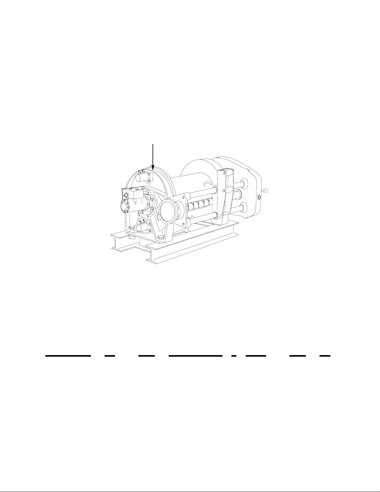
Paccar Braden BP200 Manual

BRADEN
BP200
HYDRAULIC PLANETARY
UNDERGROUND PULLING
WINCH
INSTALLATION, MAINTENANCE,AND SERVICE MANUAL
LIT2754 PB303 R3
November 2018
Printed in USA
Copyright 2018 PACCAR Inc.
All rights reserved
PACCAR Winch
800 East Dallas Street
Broken Arrow, OK 74012
www.paccarwinch.com

TABLE OF CONTENTS
FOREWORD . . . . . . . . . . . . . . . . . . . . . . . . . . . . . . . . . . . . . . . . . . . . . . . . . . . . . . . . . . . . . . . . . .2
MODEL AND SERIAL NUMBER LOCATION . . . . . . . . . . . . . . . . . . . . . . . . . . . . . . . . . . . . . . . . .2
EXPLANATION OF MODEL NUMBER . . . . . . . . . . . . . . . . . . . . . . . . . . . . . . . . . . . . . . . . . . . . .2
GENERAL SAFETY RECOMMENDATIONS . . . . . . . . . . . . . . . . . . . . . . . . . . . . . . . . . . . . . . . . .3
BASIC OPERATION . . . . . . . . . . . . . . . . . . . . . . . . . . . . . . . . . . . . . . . . . . . . . . . . . . . . . . . . . . . .4
INSTALLATION . . . . . . . . . . . . . . . . . . . . . . . . . . . . . . . . . . . . . . . . . . . . . . . . . . . . . . . . . . . . . . . .5
HYDRAULIC CIRCUITS . . . . . . . . . . . . . . . . . . . . . . . . . . . . . . . . . . . . . . . . . . . . . . . . . . . . . . . . .6
WIRE ROPE INSTALLATION . . . . . . . . . . . . . . . . . . . . . . . . . . . . . . . . . . . . . . . . . . . . . . . . . . . . .6
DIMENSIONAL DRAWINGS AND SPECIFICATIONS . . . . . . . . . . . . . . . . . . . . . . . . . . . . . . . . . .8
WINCH OPERATION . . . . . . . . . . . . . . . . . . . . . . . . . . . . . . . . . . . . . . . . . . . . . . . . . . . . . . . . . .10
CAPSTAN USE . . . . . . . . . . . . . . . . . . . . . . . . . . . . . . . . . . . . . . . . . . . . . . . . . . . . . . . . . . . . . . .11
PREVENTIVE MAINTENANCE . . . . . . . . . . . . . . . . . . . . . . . . . . . . . . . . . . . . . . . . . . . . . . . . . .12
RECOMMENDED GEAR OIL . . . . . . . . . . . . . . . . . . . . . . . . . . . . . . . . . . . . . . . . . . . . . . . . . . . .13
IDENTIFICATION OF MAJOR EXTERNAL WINCH COMPONENTS . . . . . . . . . . . . . . . . . . . . .14
TROUBLE SHOOTING . . . . . . . . . . . . . . . . . . . . . . . . . . . . . . . . . . . . . . . . . . . . . . . . . . . . . . . . .15
CHANGING EXTENSION SHAFT LENGTH . . . . . . . . . . . . . . . . . . . . . . . . . . . . . . . . . . . . . . . .19
LEVEL WIND DRIVE CONVERSION . . . . . . . . . . . . . . . . . . . . . . . . . . . . . . . . . . . . . . . . . . . . . .19
CHANGE FROM OVERWIND TO UNDERWIND . . . . . . . . . . . . . . . . . . . . . . . . . . . . . . . . . . . . .22
SERVICING THE DIAMOND SCREW LEVEL WIND . . . . . . . . . . . . . . . . . . . . . . . . . . . . . . . . . .23
REPLACING THE DRAG BRAKE DISCS . . . . . . . . . . . . . . . . . . . . . . . . . . . . . . . . . . . . . . . . . .24
SERVICING THE GEAR TRAIN, BRAKE AND DRUM . . . . . . . . . . . . . . . . . . . . . . . . . . . . . . . .25
BRAKE CYLINDER SERVICE . . . . . . . . . . . . . . . . . . . . . . . . . . . . . . . . . . . . . . . . . . . . . . . . . . .28
PLANET CARRIER SERVICE . . . . . . . . . . . . . . . . . . . . . . . . . . . . . . . . . . . . . . . . . . . . . . . . . . .31
ASSEMBLING THE WINCH GEAR TRAIN, BRAKE AND DRUM . . . . . . . . . . . . . . . . . . . . . . . .33
BRAKE VALVE AND CARTRIDGE INFORMATION . . . . . . . . . . . . . . . . . . . . . . . . . . . . . . . . . . .37
PARTS KEY . . . . . . . . . . . . . . . . . . . . . . . . . . . . . . . . . . . . . . . . . . . . . . . . . . . . . . . . . . . . . . . . .38
RECOMMENDED BOLT TORQUE . . . . . . . . . . . . . . . . . . . . . . . . . . . . . . . . . . . . . . . . . . . . . . .44
METRIC CONVERSION TABLE . . . . . . . . . . . . . . . . . . . . . . . . . . . . . . . . . . . . . . . . . . . . . . . . . .47
1

2
BP200 B -23 212/106 - 1/2 -46 H
EXPLANATION OF MODEL NUMBER
MODEL NUMBER
AND
SERIAL NUMBER
MODEL NUMBER AND SERIAL NUMBER
When information on a winch is needed, always
refer to the model number and serial number. Both
are located on the top of the motor side end plate
as indicated above.
FOREWORD
The following service instructions have been prepared to provide assembly, disassembly and maintenance infor-
mation for the BRADEN Model BP200 series winch. It is suggested that before doing any work on these units,
all assembly and disassembly instructions should be read and understood.
Some pictures in this manual may show details or attachments that are different from your winch. Also, some
components may have been removed for illustrative purposes.
Continuing product improvement may cause changes in your winch, which are not included in this manual.
Whenever a question arises regarding your BRADEN Winch or this manual, please contact BRADEN Service
Department for the latest available information.
BP200 DESIGNATES MODEL BP200 (20,000 LBS FIRST LAYER LINE PULL)
BDESIGNATES THE MODEL SERIES RELATING TO DESIGN CHANGES
23 DESIGNATES TOTAL GEAR REDUCTION
212/106 DESIGNATES HYDRAULIC MOTOR DISPLACEMENT IN CU IN./REV (212/106 = 2 SPEED MOTOR
21.2/10.6 CU IN./REV)
1/2 DESIGNATES THE INITIAL LEVEL WIND SETTING (1/2 = 0.5 INCH WIRE ROPE)
(AVAILABLE SIZES ARE 7/16 IN., 1/2 IN., AND 9/16 IN.)
46 DESIGNATES EXTENSION SHAFT LENGTH (CENTERLINE OF DRUM TO END OF SHAFT)
(00 = NO EXTENSION SHAFT)
(AVAILABLE LENGTHS ARE 46 IN., 47 IN., AND 50 IN.)
(EXTENSION SHAFT LENGTH CAN BE INCREASED BY 2 INCHES IN THE FIELD)
HDESIGNATES HYDRAULIC CLUTCH AND DRAG BRAKE CONTROLS (BLANK = AIR [STANDARD])

3
Safety for operators and ground personnel is of prime
concern. Always take necessary precautions to insure
the safety of others as well as yourself. The operator
should have a thorough knowledge of the entire
machine’s performance capabilities, and operate the
prime mover and the winch with care and concern for
the equipment, and the safety of all personnel. The fol-
lowing recommendations are offered as a general safety
guide. Local rules and regulations will also apply.
1. The BRADEN BP200 is neither designed nor intended
for use or application to equipment used in the lifting
or moving of persons.
2. Inspect rigging and winch at the beginning of each
work shift. Defects should be corrected immediately.
3. Keep equipment in good operating condition. Perform
scheduled servicing and adjustments listed in the
“Preventive Maintenance” section of this manual.
4. An equipment warm-up procedure is recommended
for all start-ups and essential at ambient temperatures
below +40oF (+5oC). Refer to "Warm-up Procedure"
listed in the “Preventive Maintenance” section of this
manual.
5. Be certain any equipment attached to the cable is
either lowered to the ground or blocked securely (i.e.
NO LOAD on the cable drum) before servicing,
adjusting or repairing the winch.
6. Before operating the winch, be sure ALL safety proce-
dures and equipment for the vehicle the winch is
mounted in are properly followed and/or in place.
7. Be sure personnel are clear of the work area
BEFORE operating the winch.
8. Read all warning and caution tags provided for safe
operation and service of the winch and become famil-
iar with the operation and function of all controls
before operating the winch.
9. Never operate winch controls unless you are properly
positioned at the operators station and you are sure
personnel are clear of the work area.
10. Assure that personnel who are responsible for hand
signals are clearly visible and that the signals to be
used are thoroughly understood by everyone.
11. Ground personnel should stay in view of the opera-
tor and clear of the winch drum. Do not allow any-
one near a winch line under tension. A safe dis-
tance of at least one and one-half (1-1/2) times the
length of the unspooled wire rope should be main-
tained.
12. The winch clutch may disengage and drop or lose
control of a load if it is not fully engaged at the
beginning of a lift or pull. The winch operator must
visually determine that the clutch is fully engaged
before lifting or pulling a load. Check the “Winch
Engaged” indicator light to make sure it is illuminat-
ed before beginning a lift or pull. The clutch must
be in its fully engaged position before this light will
illuminate.
13. Never attempt to handle wire rope when the hook
end is not free. Keep all parts of body and clothing
clear of the cable rollers, cable entry area of fair-
leads and winch drum.
14. Install guarding to prevent personnel from getting
any part of body or clothing caught at a point where
the cable is wrapped onto the drum or drawn
through the guide rollers, or where any rotating shaft
is exposed.
15. Install switches or valves that will shut off power to
the winch, in locations where they can be reached
by anyone entangled in the wire rope before being
drawn into the winch or any “pinch point”.
16. “Deadman” controls which automatically shut off
power to the winch whenever the operator leaves
his station, should be installed whenever practical.
17. Do not exceed the maximum pressure, psi (kPa) or
flow, gpm (lpm) stated in the winch specifications.
18. Operate the winch line speeds to match job condi-
tions.
19. Leather gloves should be used when handling wire
rope.
20. Never attempt to handle wire rope when the hook
end is not free.
21. When winding wire rope on the winch drum, never
attempt to maintain tension by allowing wire rope to
slip through hands. Always use “Hand-Over-Hand”
technique.
22. Never use wire rope with broken strands. Replace
wire rope.
23. Do not weld on any part of the winch.
24. Use recommended hydraulic oil and gear lubricant.
GENERAL SAFETY RECOMMENDATIONS

4
BASIC OPERATION
This emblem is used to warn against potential
or unsafe practices which COULD result in
personal injury, and product or property dam-
age if proper procedures are not followed.
CAUTION
This emblem is used to warn against unsafe
practices which COULD result in severe per-
sonal injury or death if proper procedures are
not followed.
CAUTION
WARNING
! !
25. Keep hydraulic system clean and free from contami-
nants at all times.
26. Use correct anchor for the wire rope size being
installed.
27. Do not use knots to secure or attach wire rope.
28. The BRADEN designed wire rope anchors are capa-
ble of supporting the rated load when installed prop-
erly. For additional safety, ALWAYS maintain a mini-
mum of five (5) wraps of wire rope on the drum. It
is recommended that the last five (5) wraps of wire
rope be painted bright red to serve as a visual
reminder.
29. Never allow anyone to stand under a suspended
load.
30. Avoid sudden “shock” loads or attempt to “jerk” a
load free. This type of operation may cause heavy
loads in excess of rated capacity, which may result
in failure of the wire rope and/or winch.
Safety and informational callouts used in this manu-
al include:
DESCRIPTION OF WINCH
The BRADEN BP200 winch consists of the following
sub-assemblies:
1. Motor and brake valve block with cartridges
2. Load holding friction brake assembly
3. Drum drag brake
4. Two stage planetary gear set
5. Cable drum, closure and bearings
6. Level wind system
7. Extension shaft
8. Drum clutch
The BP200 winch is supplied with provisions for either
air or hydraulically operated drum drag and drum clutch
controls. Refer to the “EXPLANATION OF MODEL
NUMBER” to determine the type of control for your
winch. Refer to “WINCH INSTALLATION” for control cir-
cuits.
NOTE: A winch built for air control CANNOT be operat-
ed hydraulically, or vice-versa, without changing the
clutch spring. Consult the BRADEN Service Department
for details.
THEORY OF OPERATION
When the winch is “at rest” with no hydraulic or air pres-
sure applied, the load holding brake is fully applied by
spring pressure, preventing the drum, drive train gears
and motor from rotating. The drum clutch is fully
engaged by spring pressure, and the drum drag brake is
not applied.
BASIC WINCH OPERATION
The winch is built with a solid hub between the input
shaft and the brake discs, which means the load holding
friction brake must be released before the winch will
rotate in either direction. When hydraulic pressure is
applied to either the haul-in or pay-out port, it is routed
to the brake release piston and blocked from flowing
through the motor. The motor cannot rotate until suffi-
cient pressure is present to open the brake valve car-
tridge. The load holding brake within the winch will
completely release at a pressure less than that required
to open the cartridge and allow the motor to rotate.
Once the cartridge is open, the planetary gears, cable
drum and extension shaft will rotate at a speed propor-
tional to the flow of oil to the motor. When the control
valve is returned to the neutral position, pressure will
drop and the cartridge will close, stopping the motor and
the load. As the pressure drops further, the internal load
holding brake is applied by spring pressure, securely
holding the load. In this normal type of operation, the
friction brake receives very little wear. All the heat gen-
erated by stopping a load is absorbed by the hydraulic
oil where it can be readily dissipated.
DRUM CLUTCH
The drum clutch is spring applied, and air or hydraulical-
ly released. The release mechanism is a mechanical
disengagement of the drum from the drive train. The

5
winch is equipped with an electrical switch that will light
the red “WINCH DISENGAGED” lamp on the freespool
panel whenever the drum is disengaged from the drive
train. In this position, wire rope can be pulled from the
drum by hand, provided the drum drag brake is not acti-
vated. The extension shaft/capstan drive can also be
operated in this mode without the cable drum rotating.
To disengage the drum, the winch should be stopped
and there should be no load on the cable drum. To
engage the clutch, the drum may have to be rotated
slightly by hand to align the internal splines. When the
clutch is fully engaged, the green “WINCH ENGAGED”
lamp on the freespool panel will be lit.
DRUM DRAG BRAKE
The BP200B has two (2) drag brake cylinders, (one (1)
on the BP200). These can be either air or hydraulically
operated. Their purpose is to control drum movement
when the winch is in freespool mode with the drum dis-
connected from the drive train. They are not designed
nor intended to hold a load. The amount of drag they
provide can be easily adjusted using one of the circuits
shown in the “INSTALLATION” section of this manual.
All hardware for these control circuits is customer pro-
vided.
LEVEL WIND
The BP200 winch is equipped with a level wind system
to ensure smooth even spooling of wire rope onto the
drum. The speed of the tension roller assembly in rela-
tion to the cable drum speed is specific to each size
wire rope. In order to change wire rope size, the chain
and sprockets driving the level wind diamond screw
must be changed. Refer to “LEVEL WIND DRIVE
GROUP CONVERSION PARTS” for additional informa-
tion. The system is provided with a manual disconnect
and hand wheel on the diamond screw. The disconnect
lever is located on the side of the winch opposite the
motor. With the lever pointing down in a vertical posi-
tion, the diamond screw is engaged. Rotating the lever
90otoward the front of the winch disengages the screw
and allows it to be rotated using the hand wheel on the
opposite end, near the motor. This feature is used to
properly align the tension roller assembly with the wire
rope on the drum. It may be necessary to perform this
alignment occasionally to compensate for normal wire
rope stretch and/or wear, or when new wire rope is
installed.
INSTALLATION
GENERAL REQUIREMENTS
The winch should be mounted with the centerline of the drum in
a horizontal position. Typically, the base will be fastened directly
to the frame of the vehicle.
When mounting the winch, the method of attachment must be
capable of withstanding the full 20,000 pound line pull.
It is important that the winch be mounted on a surface that will
not flex when the winch is in use, since this could bind the work-
ing parts of the winch. Also, be sure the winch is mounted on a
flat surface. If necessary, use shim stock to insure proper
mounting. The mounting surface should be flat within + or -.020
inches (.5 mm).
Hydraulic lines and components that operate the winch should
be of sufficient size to assure minimum back pressure at the
winch. Back pressure should not exceed 100 psi (690 kPa) for
maximum motor seal life. 150 psi (1,030 kPa) is the maximum
peak intermittent allowable back pressure. A motor case drain
from the shaft end drain port to tank is required.
The winch directional control valve must be a three-position,
four-way valve with a motor spool having both work ports open
directly to tank, when the valve is in the center position.
The extension shaft must be attached to the end of the winch
opposite the motor. The shaft may be connected to the cou-
pling in one of two positions, allowing a 2 inch adjustment in
length.
The hydraulic oil filter should have a 10 micron nominal rating
and be a full-flow type.
High quality hydraulic oil is essential for satisfactory performance
and long hydraulic system component life.
Oil having 150 to 330 SUS viscosity at 100°F (38°C) and vis-
cosity index of 100 or greater will give good results under normal
temperature conditions. The use of an oil having a high viscosity
index will minimize cold-start trouble and reduce the length of
warm-up periods. A high viscosity index will minimize changes in
viscosity with corresponding changes in temperature.
Maximum cold weather start-up viscosity should not exceed
5000 SUS with a pour point at least 20°F lower than the mini-
mum temperature.
Under continuous operating conditions the temperature of the oil
at any point in the system must not exceed 180° F (82° C).
120-140° F (49 - 60° C) is generally considered optimum.
In general terms; for continuous operation at ambient tempera-
tures between 50 and 110° F (10 to 43° C), use SAE 20W; for
continuous operation between 10 and 90° F (-12 to 32° C), use
SAE 10W; for applications colder than 10°F, contact the
BRADEN Service Department. The use of multi-viscosity
oils is generally not recommended.
Refer to the following drawings for winch control circuit,
drag brake circuit and freespool circuit.
NOTE: Continuous operation at high speeds and loads
may require the use of an oil cooler in the hydraulic sys-
tem to maintain acceptable oil temperature.

WIRE ROPE INSTALLATION
6
AIR OPERATED CONTROLS
Increasing PSI
Reduces Drag
Drag Brake
Valve
Nichols 2 Speed Motor
Brake Effective in
Both Directions
300 greater than return PSI
2500 PSI Max.
Two Speed
Shift Valve
(Manual or Solenoid)
30 GPM @
2500 PSI
Customer Provided
Freespool Valve
Air Inlet
75 PSI Min.
125 PSI Max.
Recommended Circuit For
Variable Drag Brake and
Freespool Function
Customer Provided
Freespool Indicater Circuit
Black
Green
Red
Power Source
12 VDC
Green
Red
Blue
Yellow To Freespool
Solenoid Valve
BRADEN Supplied
HYDRAULIC CONTROLS
Drag Brake Circuit
500 PSI Max.
Hydraulic Inlet
Lever Operated Master Cylinder
Customer Provided
Route Rod End Port
Back toTank to Contain
Oil Should a Seal Fail Freespool Valve
(Solenoid or Manual)
Free Spool Circuit
Hydraulic Inlet
150 PSI Min.
250 PSI Max.
Customer Provided
(Winch control circuit and Freespool indicator circuit are same as in illustration below)
150 PSI Min
250 PSI Max
90 PSI Min
150 PSI Max
To Freespool
Solenoid Valve
THE CABLE ANCHORS ALONE ON HOISTS ARE
NOT DESIGNED TO HOLD RATED LOADS. Winch
loads applied directly to the wire rope anchor may
cause the wire rope to pull free and result in the sud-
den loss of load control and cause property damage,
personal injury or death. A minimum of 3 wraps of wire
rope must be left on the drum barrel to achieve rated
load.
CAUTION
WARNING
! !
All winches are rated at bare drum line pull. As the cable
drum fills, the line pull will decrease (due to loss of
leverage), as the line speed increases (due to larger cir-
cumference). Therefore, install the minimum length of
cable possible for your application so that the winch will
operate on lower layers and deliver the maximum pull.
Using larger cable will not always increase the strength
as the larger cable may be more prone to bending
fatigue failure than smaller wire rope. Consult your wire
rope supplier for his recommendations for the wire rope
and other rigging for your application.
The wedge and anchor pocket must be clean and dry.
The end of the wire rope being anchored to the drum
must be clean and dry and not frayed. Anything on the
NOTE: A winch built for hydraulic controls CANNOT be operated with air controls, and a winch built for air controls
CANNOT be operated with hydraulic controls. The freespool piston return spring is different for each type of control.
See page 2 of this manual for location and explanation of Model Number to determine control type for your winch.
Freespool Indicator Circuit

7
end of the wire rope to keep it from fraying (i.e. tape or
wire) must not be in contact with the wedge when the
installation is complete. Consult the wire rope manufac-
turer on the proper treatment of the dead end of the wire
rope. Some rope manufacturers recommend when using
rotation resistant wire rope, that the rope end be seized,
welded or brazed before inserting the wire rope into the
wedge socket to prevent core slippage or loss of rope lay.
Take the free end of the wire rope and insert it through the
small opening on the cable drum. Loop the wire rope and
push the free end about 3/4 of the way back through the
pocket. Install the wedge as shown in figure 7, then pull
the slack out of the wire rope. The “dead” end of the rope
needs to extend slightly beyond the end of the wedge as
shown in figure 8.
Using a hammer and brass drift, drive the wedge as deep
into the pocket as possible to ensure it is fully seated and
no further movement is detected. Applying a load on the
wire rope will also help seat the wedge in the pocket.
Check to ensure the wedge does not protrude from either
end of the pocket, causing it to interfere with proper
spooling of wire rope onto the drum (see figures 9 & 10).
If there is interference or the wedge does not seat firmly,
contact the Braden Product Support Department at 918-
251-8511 to determine the proper wedge size. The
wedge shipped from the factory will properly anchor 7/16,
1/2 and 9/16 inch wire rope.
Before installing the wire rope, the levelwind roller brack-
et must be aligned with the correct rope pocket. Rotate
the drum until the correct cable pocket is on top at the
12:00 position. The correct pocket will have the smaller
Drive from
this side
Wedge and wire rope
fully seated in pocket
Correct Installation
Figure 7Figure 8
Wedge not
fully seated
Wedge pulled too far
through anchor pocket
• Wire rope not tight against wedge
• Wedge may be too large
• “Dead” end of wire rope and/or wedge may
interfere with proper spooling
• Wedge may be too small
Figure 9
Figure 10
Incorrect Installations

8
opening toward the diamond screw. Disengage the dia-
mond screw by rotating the lever on the chain case, 90o
toward the front of the winch. Using the handwheel on
the motor end of the winch, turn the diamond screw in the
same direction as the winch hauls in cable until the roller
bracket is at the flange where the cable will be anchored.
The pawl should be just starting to enter the turnaround
area of the screw. Re-engage the diamond screw.
Thread the wire rope through the spring loaded rollers
and anchor it to the winch drum. Refer to the figures on
the previous page for additional information. When
spooling cable onto the drum, the roller bracket should
lag behind where the rope is laying onto the drum by 1/2
of a rope diameter. Re-adjust the position of the roller
assembly, if needed, after beginning to spool wire rope
onto the drum. The diamond screw levelwind alone does
not assure smooth even spooling of cable onto the drum.
A light load (approx. 200 to 400 LB , 90 to 180 kg) should
be maintained on the cable to assist even spooling.
DIMENSIONAL DRAWINGS AND SPECIFICATIONS
HAUL-IN
DIAMOND SCREW
IS IN THIS POSITION
ENGAGED
1.125
FREESPOOL
PORT
SAE -4 ORB
(7/16 - 20 THD)
35.52
(902)
22.53
(572) 17.66
(449) 14.96
(380)
12.98
(330)
29.00
(737)
11.87
(302)
16.87
(429)
11.38
(289) 22.76
(578)
DISENGAGED WHEN HANDLE
Internal brake effective both directions
Minimum 150 psi (1,030 kPa), above motor outlet pressure, required to shift motor to high speed
Maximum allowable pressure at motor shift port - 2,500 psi (17,200 kPa)
Shaft end motor case drain must be drained to tank
Layer LBS kN FPM MPM LBS kN FPM MPM FT M
1 20,000 89.0 44 13 9,860 43.9 88 27 148 45.1
2 18,440 82.0 48 15 9,090 40.4 96 29 309 94.2
3 17,110 76.1 52 16 8,440 37.5 104 31 482 147
4 15,960 71.0 55 17 7,870 35.0 111 34 668 204
5 14,950 66.5 59 18 7,370 32.8 119 36 866 264
6 14,060 62.5 63 19 6,930 30.8 126 38 1,077 328
7 13,270 59.0 67 20 6,540 29.1 134 41 1,301 397
8 12,570 55.9 70 21 6,200 27.6 141 43 1,537 469
Rope Capacity
9/16 in. (14 mm)
Low Speed
Line Pull
Line Speed
High Speed
Line Pull
Line Speed
2 speed motor displacement is
21.2/10.6 cu in. (347/173 cu cm).
Performance based on:
2,500 psi (17,200 kPa) at
30 gpm (114 LPM)
Other Rope Capacities:
1/2 in. - 2,226 ft (678 M)
7/16 in. - 2,769 ft (844 M)
NOTE: Continuous operation at
high speeds and loads may
require the use of an oil cooler in
the hydraulic system to maintain
acceptable oil temperature.
Dimensions shown are
inches (millimeters)

9
BODY WIDTH DIM."A" DIM."B"
92 (2,340)
94 (2,390)
96 (2,440)
98 (2,490)
100 (2,540)
70.74 (1,800)
71.74 (1,820)
72.74 (1,850)
73.74 (1,870)
74.74 (1,900)
45.95 (1,170)
46.95 (1,190)
47.95 (1,220)
48.95 (1,240)
49.95 (1,270)
C
LDRUM
CHAINCASE DRAIN
SAE -8 ORB
(3/4-16 THD)
CHAINCASE FILL
3/4-14 NPT THD
OIL LEVEL
DRAG BRAKE PORTS (4 PLACES)
1/8-27 NPTF THD (500 PSI MAX)
CASE DRAIN
PAY-OUT PORT
SAE -8 ORB
(3/4-16 THD)
TYP 2 PORTS
HAUL-IN
PORT
FREESPOOL
INDICATOR
SWITCH
12.83
(326) 9.00
(229)
7.58
(193)
23.93
(608)
8.01
(203)
19.77
(502)
"B"
"A"
5.00
(127)
22.75
(578)
12.75
(324)
6.20
(157)
30.51
(775) 43.00
(1,090)
Approximate weights: 1,735 LBS (787 kg) - Without Extension Shaft
1,800 LBS (816 kg) - With Extension Shaft
172 173
171
1
7
6
“BR” - Brake Release Port (factory connected to brake cylinder)
“P” - Pilot or Shift Port (apply system hydraulic pressure to shift motor from low to high speed)
“A” - Normal Haul-In Port (pressurize to rotate drum counterclockwise when viewed from motor end)
“B” - Normal Pay-Out Port (pressurize to rotate drum clockwise when viewed from motor end)
BRADEN
The shaft-end motor
case drain port must be
plumbed to tank.

10
WINCH OPERATION
The following warnings are basic to safe winch operation. Please read them completely and follow them each time
your BP200 winch is operated.
A partially engaged drum clutch may “jump out” of
engagement causing a sudden loss of load control
which may result in property damage, personal
injury or death. Before operating the winch, be sure
the drum clutch is fully engaged by observing the
green light on the freespool panel. The green light
will only be lit if the drum clutch is fully engaged. DO
NOT attempt to disengage the clutch when there is
tension on the wire rope.
CAUTION
WARNING
! !
Ground personnel must stay in view of the operator
and clear of the load and winch drum. Do not allow
personnel near the winch line under tension. Do not
allow personnel to be in line with winch load. A safe
distance of at least 1 and 1/2 times the working
length of the cable should be maintained by ground
personnel. A broken cable and/or lost load may
cause property damage, personal injury or death.
CAUTION
WARNING
! !
When possible, position the winch such that the center-
line of the drum is perpendicular to the load. The angle
the winch must pull from (fleet angle) must not exceed
5o. If the fleet angle exceeds 5o, the cable will not
spool correctly resulting in damaged cable and prema-
turely worn winch components.
Disengage the drum clutch and apply the drum drag
brake to control drum over-spin or “birdnesting”. You
can now pull cable off the drum by hand.
Securely attach the end of the cable to the load in such
a manner to avoid damage to the load or cable. Fully
engage the drum clutch.
Operate the winch control valve smoothly to avoid “jerk-
ing” the load. The winch should be operated at the
slowest practical speed for your application to maintain
maximum load control. If necessary, secure the load in
position and pay-out enough cable to remove all tension
on the cable and drum.
Be sure the drum clutch is fully engaged by observing
the green light on the freespool control panel. DO
NOT operate the winch to pull in a load unless this
light is on.
CAUTION
Disconnect the winch cable from the load. Wind the
cable back onto the winch drum. Be careful to maintain
a minimum fleet angle, and sufficient tension to cause
the cable to spool prpoerly onto the drum.
If maintaining tension on the cable by hand, always
wear leather gloves and never attempt to maintain
tension by allowing winch cable to slip through hands.
Always use “hand-over-hand” technique, being care-
ful to keep hands and clothing away from winch drum
and level wind rollers.
CAUTION

11
CAPSTAN USE
Braden has two types of capstans available. One is a quick disconnect bayonet type, the other is a bolt-on style.
ɀBefore installing a bayonet type capstan, make certain the spring is properly located in the bore. The spring
holds the capstan in the lock position on the extension shaft. If the spring is omitted, the capstan may come
off the extension shaft and cause a sudden loss of load control which may result in property damage, personal
injury or death. Also, closely inspect the edges of the lock pocket to make certain they are still sharp and not
rounded from extensive use. A badly worn lock pocket may prevent the capstan from locking securely to the
extension shaft which could allow the capstan to come off the extension shaft and cause a sudden loss of load
control which may result in property damage, personal injury or death.
ɀWhen installing a bolt-on capstan, make sure that a 3/4 in. X 5 1/4 in. long (19 X 133 mm) Grade 8 capscrew
and self-locking nut are used. A soft bolt or pin may shear off and cause a sudden loss of load control which
may result in property damage, personal injury or death.
ɀMake certain that the vehicle is positioned such that the capstan load line and hand line are perpendicular to
the center of the capstan barrel. Do not allow rope to pull against the flange of the capstan as rope may get
damaged or may “jump” over the flange and cause a sudden loss of load control which may result in proper-
ty damage, personal injury or death.
ɀBefore operating the capstan, be sure the drum clutch is disengaged. The red “winch disengaged” light on the
freespool panel will be lit.
CAUTION
WARNING
! !
The load holding brake on the BP200 winch is effective in both directions, allowing rope to be wound around the
capstan in either direction.
To install the bayonet type capstan, push the capstan onto the extension shaft, against spring tension, then turn
counter-clockwise (viewed from the outside) to the stop. Release the capstan and verify that the spring has pushed
the capstan outward into the lock position.
Exposed areas of extension shafts and/or capstan shafts are dangerous. Clothing and other items may become
tangled and wrapped around the shaft when it is rotating. Appropriate guarding should be installed to prevent
any part of the body or clothing from contacting the shaft when it is rotating. Failure to provide appropriate guard-
ing could result in property damage, personal injury or death.
CAUTION
WARNING
! !
Spring
Sharp Corner
of Lock-Pocket
“Good”
Spring Missing
OR
Worn Corner
of Lock-Pocket
DO NOT USE

12
PREVENTIVE MAINTENANCE
A regular program of preventive maintenance for your
Braden BP200 winch will minimize the need for emer-
gency servicing and promote long life and trouble-free
service.
The service intervals suggested in this manual will opti-
mize component service life. The intervals may be
gradually increased or decreased with experience of a
particular lubricant and evaluation of your application.
ɀNever attempt to service a winch while the prime
mover engine is running. Accidental engagement
of the winch may result in property damage, per-
sonal injury or death.
ɀMake certain all load is removed from the winch
cable and cable drum before servicing the winch.
A cable under tension may rapidly unspool result-
ing in property damage, personal injury or death.
CAUTION
WARNING
! !
Daily when winch is in regular use:
ɀInspect the cable and rigging for broken wires or
other damage as recommended by the wire rope and
rigging manufacturer.
ɀVisually inspect the winch and drum clutch controls
for signs of damage or oil leakage. Shift the winch
into freespool. Be sure the red “winch disengaged”
light is on and the drum can be turned by hand. Re-
engage the drum clutch and be sure the green
“winch engaged” light is on.
Weekly
ɀPerform all daily inspections.
ɀCheck winch gear oil level at the sight glass in the
chain case. If necessary, fill to the center of the sight
glass with the recommended gear oil. Over filling
may result in leaks and/or over heating. Operating
the winch at a low oil level may result in rapid wear
of the internal components and gears.
ɀLubricate the grease fittings on the diamond screw,
pawl and extension shaft. Use a high quality moly
type grease with a rating of NLGI-2 or better.
ɀInspect and retighten as required, all winch mounting
fasteners. Inspect and repair as required, all winch
mounting brackets and welds.
ɀWipe off any accumulated dust and apply a light coat
of rust preventive oil to diamond screw and guide
bars.
Monthly
ɀCheck and adjust as required, the hydraulic system
relief valve to ensure proper performance and com-
ponent protection.
ɀService the hydraulic system filters/strainers as rec-
ommended by the equipment manufacturer.
Yearly
ɀChange winch gear oil.
Oil should preferably be changed soon after operat-
ing the winch, while the oil is warm. Place winch in a
level position. Slowly rotate the cable drum until the
drain plug in the drum closure is aligned with the
hole in the motor end support bracket, directly below
the motor. Stop the hydraulic system prime mover
so the winch cannot be accidentally operated while
changing oil.
Chain Case
Drain
Place a suitable container under the chain case drain
and remove the drain plug.
Vent
Install a short piece of 3/4 in. threaded pipe into the
threads in the drum closure. Place a suitable container
under the open end of the pipe. Reach through the pipe
with a 3/16 in. Allen wrench and remove the oil drain
plug. While the oil is draining, remove the vent plug and
bushing and clean them in safety solvent. It is very
important to keep the vent clean and unobstructed. DO
NOT paint over the vent or replace it with a solid plug.
Rotate the drum to align the oil hole with the hole in the
end bracket at the 3:00 position. Fill the drum with oil to
the bottom of the hole and replace the drain plug.
Install the drain plug in the chain case and fill the case
to the center of the sight glass. Install the bushing and
vent plug. The drum and chain case use the same oil.
Refer to “Recommended Gear Oil” on next page.
Motor and drum
drag cylinders
not shown in
this drawing for
clarity.
Drum Oil
Drain

13
Wire Rope
Inspect the entire length of wire rope according to the
wire rope manufacturer’s recommendations.
Warm-up Procedures
A warm-up procedure is recommended at each start-up and is
essential at ambient temperatures below +40°F (4°C).
The prime mover should be run at its lowest recommended RPM
with the hydraulic winch control valve in neutral allowing sufficient
time to warm up the system. The winch should then be operated
at low speeds, forward and reverse, several times to prime all
lines with warm hydraulic oil, and to circulate gear lubricant
through the planetary gear sets.
Failure to properly warm up the winch, particularly
under low ambient temperature conditions, may
result in temporary brake slippage due to high back
pressures attempting to release the brake, which
could result in property damage, personal injury or
death.
CAUTION
WARNING
! !
Recommended Planetary Gear Oil
Field experience, supported by extensive engineering
tests, indicates the use of the proper planetary gear oil is
essential to reliable and safe operation of the winch brake
and obtaining long gear train life.
For simplicity, BRADEN has listed one (1) readily avail-
able product in each temperature range which has been
tested and found to meet our specifications. This is not to
say that other lubricant brands would not perform equally
as well.
If the following lubricant brands are not available in your
area, make certain your lubricant vendor supplies you
with oil that is equivalent to those products listed below.
BRADEN planetary winches are factory filled with Texaco
Meropa 150 or equivalent API GL-2/3 gear oil.
Mounting Bolts
Tighten all winch base mounting bolts to recommended
torque after the first one hundred (100) hours of opera-
tion, then every 1,000 operating hours, or six (6)
months, whichever occurs first.
SHA DED A REA S NOT RECOMMENDED FOR SEV ERE A PPLICA TIONS
SUCH A S: SUSTA INED FA ST DUTY CY CLES OR FREQUENT LIFTING.
oC -40 -35 -30 -25 -20 -15 -10 -5 0 5 10 15 20 25 30 35 40 45 50 55 oC
TEXACO MEROPA 150 OR EQUIVALENT
AGMA NO. 4EP
MOBIL SHC 629 OR TEXACO PINNACLE 150
PREVAILING AMBIENT TEMPERATURE
oF -40 -30 -20 -10 0 10 20 30 40 50 60 70 80 90 100 110 120 130 oF
TEXACO MEROPA 220 OR EQUIVALENT
AGMA NO. 5EP
RECOMMENDED GEAR OIL

14
IDENTIFICATION OF MAJOR EXTERNAL WINCH COMPONENTS
1
2
3
3
5
4
6
7
8
9
10
11
13
14
12
1. Hydraulic Motor
2. Brake Valve Block and Cartridges
3. Drum Drag Brake Cylinders (2)
4. Diamond Screw Handwheel
5. Diamond Screw
6. Level Wind Roller Assembly
7. Chain Case Drain Plug
8. Oil Level Sight Glass
9. Diamond Screw Disconnect Lever
10. Vent Plug
11. Cable Anchor Pocket
12. Chain Case for Level Wind Mechanism
13. Extension Shaft
14. Winch Mounting Base
15. Grease Fittings (3)
16. Freespool Pressure Port
17. Freespool Switch
15
15
15 16
17

15
TROUBLE SHOOTING
TROUBLE REMEDY
PROBABLE CAUSE
If a winch ever exhibits any sign of erratic operation, or load control difficulties (i.e. load creeping or chattering)
appropriate troubleshooting tests and repairs should be performed immediately. Continued operation in this manner
may result in property damage, serious personal injury or death.
A
The winch will not pay-out or haul-in
the load smoothly.
CAUTION
WARNING
! !
Disassemble brake to inspect
brake discs.
2. Friction brake will not release as
a result of damaged brake
discs.
Check brake cylinder seal as
follows:
A. Disconnect the hose from the
brake valve block. Connect a
hand pump with accurate 0-
2,000 psi (13,800 kPa) gauge
and shut-off valve to the hose
(–4 J.I.C. fitting).
B. Apply 1,000 psi (6,900 kPa) to
the brake. Close shut-off valve
and let stand for five (5) min-
utes.
C. If there is any loss of pressure in
five (5) minutes, the brake cylin-
der should be disassembled for
inspection of the sealing sur-
faces and replacement of the
seals. Refer to “Motor Support-
Brake Cylinder Service”.
1. The friction brake may not be
releasing as a result of a defec-
tive brake cylinder seal.
NOTE: If the brake cylinder seal
is defective the winch drum will
fill with hydraulic oil and slowly
fill the chain case. A fast leak
may cause oil to leak around the
motor end drum seal. A slower
leak may fill the chain case and
leak oil from the vent.
Oil leaks from vent plug. Same as A1.
Peak intermittent system back
pressure must not exceed 150
psi (1,030 kPa). Inspect
hydraulic system for a restriction
in the return line from the control
valve and/or from the motor
case drain to the reservoir. Be
sure control valve and plumbing
is properly sized to winch motor.
Oil analysis may indicate con-
tamination has worn motor shaft
and seal. Thoroughly flush
entire hydraulic system and
install new filters and oil. Install
new motor seal.
1. Same as A1.
2. Motor seal may be defective as a
result of high system back pres-
sure or contaminated oil.
B

16
TROUBLE REMEDY
PROBABLE CAUSE
The same as B2.
Same as A2.
1. Excessive system back pres-
sure acting on the brake release
port.
2. Friction brake will not hold due
to worn or damaged brake
discs.
The brake will not hold a load with
the control lever in neutral.
C
Reinforce mounting surface.
If necessary, use shim stock to
level winch. Refer to “Winch
Installation”.
First loosen, then evenly retight-
en all winch mounting bolts to
recommended torque.
Check relief pressure as fol-
lows:
A. Install an accurate 0-4000 psi
gauge into the inlet port of the
brake valve.
1. The winch may be mounted on
an uneven or flexible surface
which causes distortion of the
winch base and binding of the
gear train. Binding in the gear
train will absorb horsepower
needed to pull the rated load
and cause heat.
2. System relief valve may be set
too low. Relief valve needs
adjustment or repair.
The winch will not pull the rated load
D
B. Apply a stall pull load on the
winch while monitoring pres-
sure.
C. Compare gauge reading to
winch specifications. Adjust
relief valve as required.
NOTE: If pressure does not increase
in proportion to adjustment,
relief valve or pump may be
contaminated or worn out. In
either case, the relief valve may
require disassembly or replace-
ment.
Same as remedies for Trouble
D1 & D2.
Same as remedies for Trouble
E2.
Refer to winch performance
charts for additional information.
Perform rigging service as rec-
ommended by vehicle manufac-
turer.
3. Be certain hydraulic system
temperature is not more than
180oF (82oC). Excessive
hydraulic oil temperatures
increase motor internal leakage
and reduce motor performance.
4. Winch line pull rating is based
on 1st layer of wire rope.
5. Rigging and sheaves not oper-
ating efficiently.

17
TROUBLE REMEDYPROBABLE CAUSE
Same as remedies for Trouble D1.
Thoroughly clean exterior and flush
interior.
Fill/drain to proper level.
Same as remedies for Trouble D2.
Prime mover low on horsepower or
R.P.M. Tune/adjust prime mover.
Check suction line for damage.
If pump is belt driven, belts are slip-
ping. Replace/tighten belts.
Pump worn. Replace pump.
Disassemble winch to inspect and/or
replace worn parts.
1. Same as D1.
2. Be certain that the hydraulic
system temperature is not more
than 180 degrees F. Excessive
hydraulic oil temperatures may
be caused by:
A. Plugged heat exchanger.
B. Too low or too high oil level in
hydraulic reservoir.
C. Same as D2.
D. Hydraulic pump not operating
efficiently.
3. Excessively worn or damaged
internal winch parts.
The winch runs hot.
E
F
The wire rope does not spool
smoothly on the drum.
Consult wire rope manufacturer
for recommendation of wire
rope that best suits your appli-
cation.
Replace wire rope and conduct
operator/rigger training as
required.
Roller assembly should lag
behind where the rope is laying
onto the drum by 1/2 a rope
diameter. Adjust as required.
1. Could be using the wrong lay
rope. There is a distinct advan-
tage in applying rope of the
proper direction of lay. When the
load is slacked off, the several
coils on the drum will stay clos-
er together and maintain an
even layer. If rope of improper
lay is used, the coils will spread
apart each time the load is
removed. When winding is
resumed, the rope has a ten-
dency to criss-cross and overlap
on the drum. The result is often
flattened and crushed rope.
2. The winch may have been over-
loaded, causing permanent set
in the wire rope.
3. Levelwind roller assembly may
be out of adjustment

18
TROUBLE REMEDYPROBABLE CAUSE
G
When winch is shifted into freespool,
winch continues to operate normally.
Check pressure at freespool port.
Refer to page 6 for air and hydraulic
pressure ranges.
Replace piston O-ring seals.
Be sure there is no tension on the
wire rope when shifting to freespool.
Check winch model number and ver-
ify type of control circuit required.
1. Insufficient pressure at the
freespool pressure port.
2. Damaged O-ring seals in
freespool piston.
3. There may be a load on the
drum and gear train.
4. A winch built for hydraulic con-
trols cannot be shifted with air.
H
When winch is shifted into freespool,
red light on console does not come
on.
Check solenoid and replace as
required. (Terminals 30 and 87a are
connected with coil de-energized.
Terminals 30 and 87 are connected
with coil energized. Coil is between
terminals 85 and 86)
Check bulb and replace as required.
Check switch and replace as
required. (Switch is normally open,
closed when plunger is pushed in)
1. Faulty solenoid.
2. Burned out bulb.
3. Faulty freespool switch on
winch.
I
Winch will not remain in freespool
mode. (winch drum re-engages to
winch drive train)
1. Leaking seals on the freespool
piston.
Replace the O-rings and backup
rings on the freespool piston.
F Continued
4. The levelwind ratio does not
match the cable being used.
Verify levelwind ratio is correct for
the size cable being used.

19
CHANGING EXTENSION SHAFT LENGTH
Extension shafts are available as 46 in., 47 in., and 50 in. lengths. (from centerline of drum to end of shaft).
The extension shaft is connected to the winch with a coupling that has two (2) sets of holes in it, 2 inches apart.
This allows the 46 in. shaft to be extended to 48 in., the 47 in. shaft to 49 in. and the 50 in. shaft to 52 in.
Follow the steps below to change the effective length of the extension shaft .
Remove the twelve (12) capscrews and lockwashers
securing the torque tube to the chain case, and slide the
torque tube toward the end of the extension shaft,
exposing the coupling. Remove the nut, washer and
capscrew that are furthest from the winch. Carefully
slide the extension shaft outward until the hole in the
shaft alignes with the outer hole in the coupling.
Replace the capscrew, washer and nut and torque to
the correct value. Slide the torque tube back against
the chain case and replace the capscrews and washers,
and torque to the correct value. Be sure the grease fit-
ting in the torque tube remains at the 12:00 o’clock posi-
tion.
The torque tube and extension shaft weigh approxi-
mately 65 LBS (29 kg). The entire assembly may
easily become disengaged from the coupling during
this procedure, resulting in personal injury. If neces-
sary, provide support for the torque tube and exten-
sion shaft as it is slid outward.
CAUTION
The capscrews used in the coupling are Grade 8.
DO NOT replace either of them with a soft bolt or
pin. A soft bolt or pin may shear off and cause a
sudden loss of load control which may result in
property damage, personal injury or death.
CAUTION
WARNING
! !
LEVEL WIND DRIVE CONVERSION
The level wind mechanism on the BP200 winch operates at a speed specific to the size of wire rope being used.
Whenever wire rope size is changed, some sprockets and chains will have to be changed for the level wind mecha-
nism to operate at the correct speed. The following table shows the correct sprockets and chains required for each
size wire rope.
Wire Rope Size 5/16 in. 3/8 in. 7/16 in. 1/2 in. 9/16 in.
Primary Sprocket 100017 29211 29211 29211 29211
Intermediate Sprocket 100018 29780 29616 29617 29636
Final Sprocket 100019 29209 29209 29209 29209
Drive Chain 100020 29433 29433 29641 29641
Drive Chain 100021 29632 29632 29433 29433
Connecting Link 100115 29435 29435 29435 29435
Offset Link 100114 N.A. 29434 29434 29434
BP200 Conversion Parts for Level Wind Drive
The following steps outline the procedure for changing the sprockets and chain to enable the level wind drive to
operate with a different size wire rope.
Table of contents
Other Paccar Winch manuals
Popular Winch manuals by other brands

Badland
Badland ZXR 12000 user manual

Harken
Harken CLR 600 Installation and maintenance manual

Warrior Winches
Warrior Winches 80RVSHY owner's manual

Ingersoll-Rand
Ingersoll-Rand BU7A Parts, operation and maintenance manual

Ironton
Ironton 54127 owner's manual

Ramsey Winch
Ramsey Winch RAM-LOK G-200 Series Operating, Service and Maintenance Manual

Kolpin Outdoors
Kolpin Outdoors KAWASAKI MULE QUICK-MOUNT 4500 Assembly & owners manual

Warrior Winches
Warrior Winches TROJAN 40PUS12 owner's manual

FULTON
FULTON F2 FW32000301 instructions

Harken
Harken 60.2STEC Installation and maintenance manual

Comeup
Comeup CWL-200L quick start guide

Warn
Warn 60272 Instalation instruction