Theta Digital Casablanca IV User manual

13
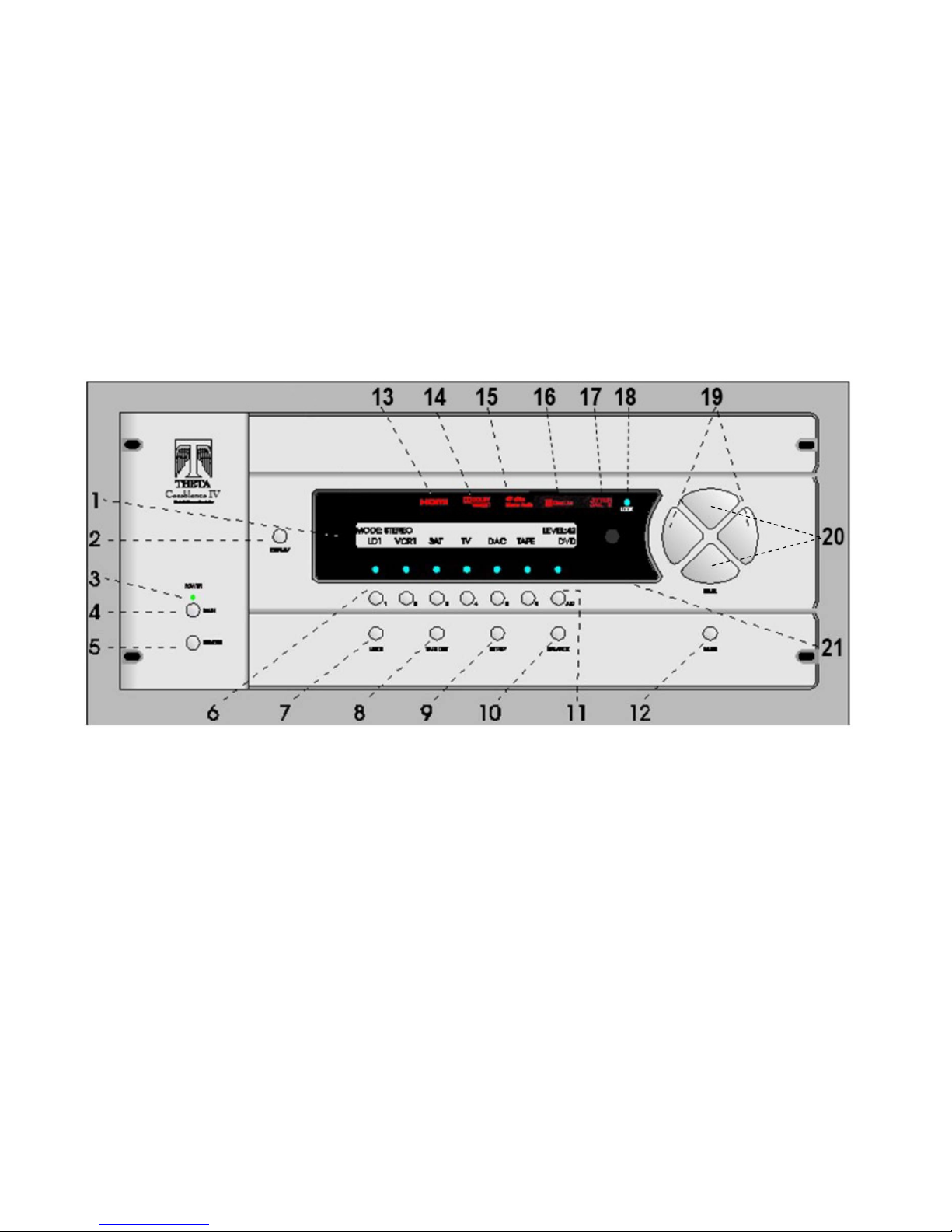
Effective October 1, 2014 the Analog Input Level display was
deleted from the Casablanca IV.
The Revised Front Panel Layout is shown in Figure 6, below.
Figure 6 - Front Panel Layout

THETA DIGITAL
Casablanca IV
Owner’s Manual
V 4.02
Digital Done Right
™

ii
PREFACE
CONGRATULATIONS
You have just acquired the most advanced component for the control and processing of audio and video ever to
have been developed.
IMPORTANT
Save all packaging in a dry place away from fire hazards. Your Casablanca IV is a precision electronic instrument
and should be properly packaged any time shipment is made. In the unlikely event that you have to return your
Casablanca IV to the factory for service, or if you send it to us for updating, the original packaging will best protect
the unit from shipping damage.
In order to achieve the fullest flexibility and enjoyment from your Casablanca IV, we at Theta recommend that you
read this manual in full before connecting the unit to your audio/video system.
WARNING
United Stated law prohibits disposition of these commodities to Libya, Laos, North Korea, Cambodia or Cuba
unless otherwise authorized by the United States.
NOTE:
This equipment has been tested and found to comply with the limits for a Class B digital device, pursuant to Part
15 of the FCC rules. These limits are designed to provide reasonable protection against harmful interference in
a residential installation. This equipment generates, uses and can radiate radio frequency energy and, if not
installed and used in accordance with the instructions, may cause harmful interference to radio communications.
However, there is no guarantee that interference will not occur in a particular installation. If this equipment does
cause harmful interference to radio and television reception, which can be determined by turning the equipment
off and on, the user is encouraged to try to correct the interference by one or more of the following measures:
* Reorient or relocate the receiving antenna.
* Increase the separation between equipment and receiver.
* Connect the receiver into an outlet on a circuit different from that which the Casablanca IV is connected to.
Acknowledgments
Casablanca IV is manufactured under license from Dolby Laboratories. “Dolby”, “Pro Logic”, “Dolby TrueHD”
and the double-D symbol are registered trademarks of Dolby Laboratories.
Casablanca IV is manufactured under license from Digital Theater Systems, Inc. U.S. Pat. No's. 5,451,942;
5,956,674; 5,974,380; 5,978,762; 6,226,616; 6,487,535 and other U.S. and world-wide patents issued and
pending. "DTS", "DTS-ES", "DTS-ES", "Neo:6", "DTS 96/24" and “DTS Master Audio” are trademarks of Digital
Theater Systems, Inc. Copyright 1996, 2003 Digital Theater Systems, Inc. All Rights Reserved.
© 2000-14 Theta Digital. All rights reserved.
This manual is also available for download as a PDF file at Theta Digital’s website. http://www.thetadigital.com
No part of this publication may be reproduced or transmitted in any form or by any means, electronic or
mechanical, for any purpose, without the express written permission of Theta Digital.

iii
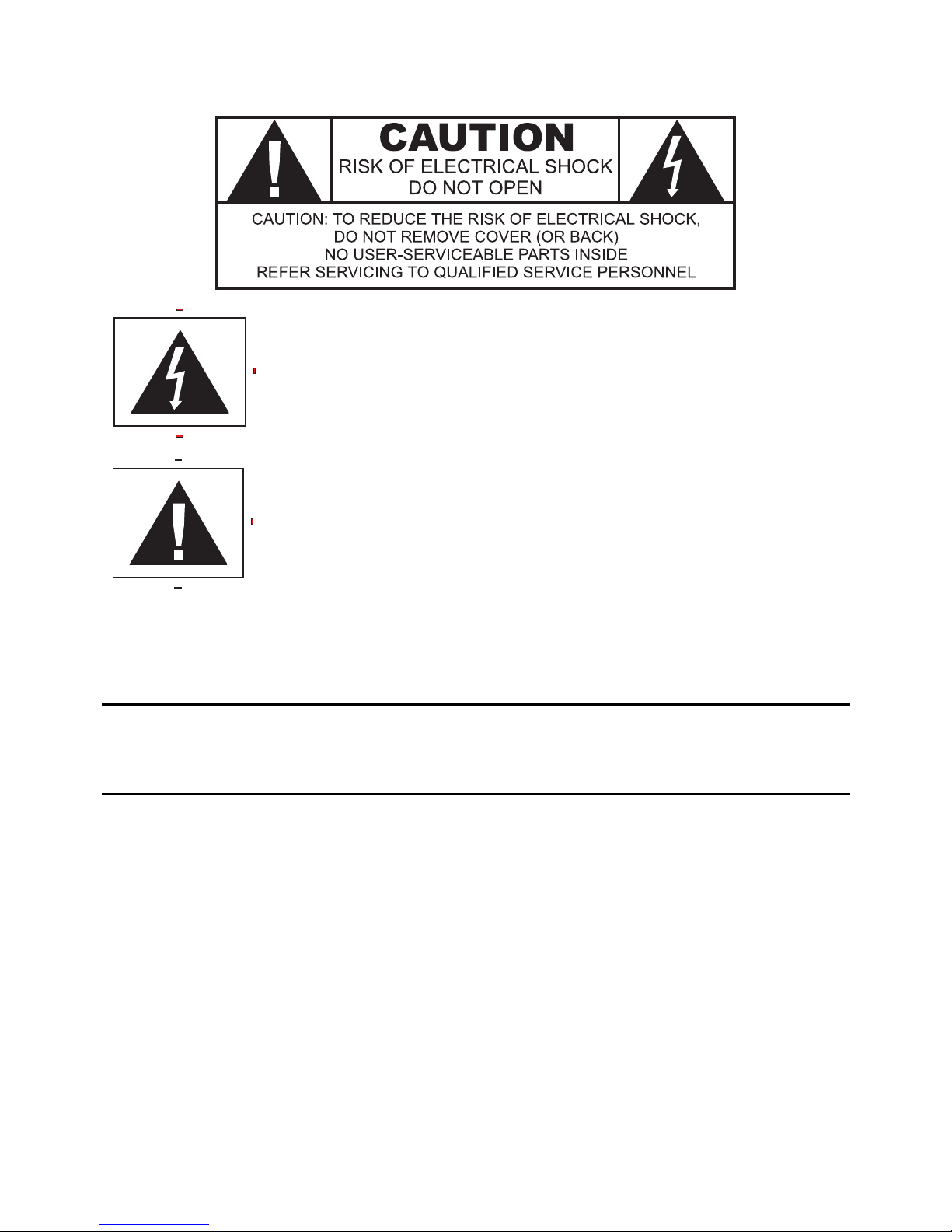
The lightning flash with arrowhead symbol, within an equilateral
triangle, is intended to alert the user to the presence of uninsulated
“dangerous voltage” within the product’s enclosure that may be of
significant magnitude to constitute a risk of electric shock to persons.
The exclamation point within an equilateral triangle is intended to alert
the user to the presence of important operating and maintenance
(servicing) instructions in the literature accompanying the product.
WARNING
TO REDUCE THE RISK OF FIRE OR ELECTRIC SHOCK,
DO NOT EXPOSE THIS PRODUCT TO RAIN OR MOISTURE
CAUTION: TO PREVENT ELECTRIC SHOCK, DO NOT USE THE (POLARIZED) PLUG WITH AN
EXTENSION CORD, RECEPTACLE OR OTHER OUTLET UNLESS THE BLADES CAN BE FULLY
INSERTED TO PREVENT BLADE EXPOSURE.

iv
Casablanca IV Identification Record
This information is for your records and for future identification of the Casablanca IV. Please take a moment
to fill out all pertinent data now, and as upgrades and/or options are installed. Whenever upgrades, inquiries
and/or changes are requested, the serial number will be required.
SERIAL NUMBER
DATE PURCHASED
DEALER’S NAME
DEALER’S ADDRESS/PHONE
INSTALLED CARDS/OPTIONS
(Dateofinstallation)

v
SAFETY PRECAUTIONS
Please carefully read each item of the operating instructions and safety precautions before using this product.
Use extra care to follow the warnings written on the product itself and/or in the operating instructions. Keep
the operating instructions and safety precautions for future reference.
CAUTION: TO REDUCE THE RISK OF ELECTRICAL SHOCK, DO NOT REMOVE ANY OF THE COVER
PANELS.
NO USER-SERVICEABLE PARTS INSIDE. REFER ALL SERVICING TO QUALIFIED SERVICE
PERSONNEL ONLY.
TO PREVENT FIRE OR SHOCK HAZARD, DO NOT ALLOW LIQUIDS TO SPILL OR OBJECTS TO FALL
INTO ANY OPENINGS OF THE PRODUCT.
THIS UNIT IS SUPPLIED WITH A 3 PIN GROUNDED AC PLUG. ALWAYS INSERT THE AC PLUG INTO A
GROUNDED OUTLET. DO NOT REMOVE THE GROUND PIN OR DISABLE THE GROUND FOR ANY
PURPOSE.
BEFORE MAKING ANY CONNECTIONS TO THE CASABLANCA IV, FIRST TURN OFF THE POWER AND
THEN DISCONNECT THE AC POWER CORD.
WHEN INSTALLING THE CASABLANCA IV IN YOUR SYSTEM, MAKE CERTAIN TO ALLOW A MINIMUM
OF 3 INCHS OF VENTILATION ON EACH SIDE OF THE UNIT. ALSO ALLOW AT LEAST 4 INCHS OF
VENTILATION SPACE ABOVE THE UNIT. IMPROPER VENTILATION OF THE UNIT MAY CAUSE
OVERHEATING, WHICH MAY DAMAGE THE UNIT AND CAUSE A FIRE. PLACE THE UNIT ON A SOLID
SURFACE ONLY. I.E. NOT ON CARPET, ETC.
DO NOT PLACE THE CASABLANCA IV NEAR HEAT SOURCES SUCH AS DIRECT SUNLIGHT, STOVES,
HEAT REGISTERS, RADIATORS OR OTHER HEAT PRODUCING EQUIPMENT.
TO PREVENT DAMAGE TO THE ANALOG OUTPUT CIRCUITRY, BE CERTAIN NOT TO SHORT THE
OUTPUT SIGNAL PIN(S) TO GROUND. ENSURE THAT YOUR AUDIO OUTPUT CABLES DO NOT HAVE
ANY INTERNAL SHORTS BEFORE CONNECTING THEM TO THE CASABLANCA IV.
IF REPLACEMENT OF THE AC LINE FUSE BECOMES NECESSARY, REPLACE ONLY WITH SAME
VALUE AND TYPE OF FUSE. NEVER BYPASS THE FUSE.
IF THE AC CORD BECOMES DAMAGED, DO NOT USE IT. IMMEDIATELY REPLACE IT WITH A NEW
ONE OF THE SAME OR BETTER RATING.
AFTER MARKET and THIRD PARTY MODIFICATIONS
Please note that any aftermarket and/or third party modifications will void the warranty. In the case of changing
the feet on a unit, in order to prevent any damage (which will also not be covered under warranty), please
verify that the screws being used to secure non Casablanca IV feet do not screw any deeper into the chassis
than the original ones. The original screw is 10-32 by 3/8 and goes into the chassis 1/5 inch.

6
TableofContents
PREFACE ........................................................................................................................................................... ii
WARNING ....................................................................................................................................................... iii
Casablanca IV Identification Record .............................................................................................................. iv
SAFETY PRECAUTIONS ............................................................................................................................... v
AFTER MARKET and THIRD PARTY MODIFICATIONS ........................................................................... v
INTRODUCTION ................................................................................................................................................ 7
Getting to know your Casablanca IV .............................................................................................................. 7
Burn In Time ................................................................................................................................................ 7
IMPORTANT NOTICE .................................................................................................................................... 8
Reference Manual Conventions ..................................................................................................................... 8
Glossary of Terms and Abbreviations ............................................................................................................. 9
Casablanca IV Block Diagram - Input Processing Sections ......................................................................... 10
Front Panel Layout ........................................................................................................................................ 13
Rear Panel Layout ........................................................................................................................................ 14
Introduction to the User interface .................................................................................................................. 20
Before you begin ....................................................................................................................................... 20
Casablanca IV Default Settings .................................................................................................................... 22
Overall Setup Procedure Flowchart .............................................................................................................. 23
................................................................................................................................................................... 23
Figure 12: Casablanca IV Basic Set-up Flow Chart ................................................................................. 23
Step by Step Speaker Configuration ......................................................................................................... 24
Speaker Levels .......................................................................................................................................... 24
Speaker Delays ......................................................................................................................................... 24
Dolby Digital, DTS Setup ........................................................................................................................... 28
Remaining Setup ....................................................................................................................................... 28
FRONT PANEL OPERATIONS ........................................................................................................................ 42
Input Select Menus ....................................................................................................................................... 42
Changing Inputs and Input Select Pages .................................................................................................. 42
Selecting Mapped Input Jacks for the Currently Selected Input ............................................................... 42
Search Order ............................................................................................................................................. 44
MODE Function ............................................................................................................................................ 45
TAPE OUT Function ..................................................................................................................................... 48
SETUP Function ........................................................................................................................................... 49
DAC Configuration .................................................................................................................................... 49
SETUP INPUT (Settings specific to each of the 12 Input Select Buttons) ................................................ 50
Setup Global .............................................................................................................................................. 69
Macros ....................................................................................................................................................... 74
BALANCE Function ...................................................................................................................................... 76
Front/Rear and Left/Right Balance ............................................................................................................ 76
Center and Sub Balance ........................................................................................................................... 76
Analog Input Level Override ...................................................................................................................... 76
STATUS Function ......................................................................................................................................... 77
REMOTE CONTROL OPERATIONS ............................................................................................................... 81
Input Select Menus ....................................................................................................................................... 81
Changing Inputs and Input Select Pages .................................................................................................. 81
Selecting Mapped Input Jacks for the Currently Selected Input ............................................................... 81
Mute ........................................................................................................................................................... 81
Display ....................................................................................................................................................... 81
Global Phase ............................................................................................................................................. 81
STATUS Display ........................................................................................................................................... 82
MODE Function ............................................................................................................................................ 82
Appendix ATroubleshooting Guide ........................................................................................................ 8 5
Appendix BSpeaker Placement Guides ................................................................................................. 86
Six Shooter Wiring Diagram .......................................................................................................................... 88
Appendix CRemote Extender Jack Technical Description and Protocol ............................................... 89
Appendix DUpgrading/Re-installing Casablanca IV Software ............................................................... 90
Appendix E Reinstalling Casablanca Settings………………………………………………………………..90
Appendix F Dirac Live…………………………………………………………………………………………..90
Appendix GSpecifications ....................................................................................................................... 91

7
INTRODUCTION
Welcome to a new world of possibilities. Casablanca IV is by far the most advanced surround sound processor/home
theater controller available today. It offers the advantages of Theta’s legendary mastery in digital signal processing and
sound quality unapproachable by any other equipment.
Getting to know your Casablanca IV
Despite Casablanca IV’s great technical sophistication, we believe in making it as easy as possible for you to use. We
think you’ll enjoy the intuitive way the Casablanca IV works. Rather than offer a frustrating bewilderment of little used
functions in constant view vying for your attention, Casablanca IV is structured systematically by function.
The “user interface” is based on simple logic. For example, when a function button is pressed, you can make changes
within its menu(s) and press the same function button again to exit that function. (The same button that got you in gets
you back out).
This Casablanca IV has been put through a rigorous and unique testing procedure that insures that it will last for many
years with minimal service requirements. This procedure includes the following:
• All assembled circuit boards are given a thorough visual inspection and are then tested in a bench-reference
Casablanca IV.
• The tested assembled circuit boards are installed in a new Casablanca IV and the whole unit is tested for every
function and parameter.
• The unit is put on a burn-in torture rack for 100 hours to test for any possible component failures.
• The Casablanca IV is tested on an audio analyzer for all pertinent parameters.
• The Casablanca IV is put through a final bench test wherein every possible feature, mode and parameter is
checked.
• The unit has all remaining chassis components installed and then undergoes a complete visual inspection, which
assures that all Casablanca IVs meet visual specifications.
• The unit is then put through a critical listening test.
Burn In Time
This unit has a break in period of about 2 weeks during which continuous improvement in sound quality will be observed.
It is recommended that music be played continuously through the unit during this time to expedite the break in period.

8
IMPORTANT NOTICE
I. Due to the computer-based circuitry used in Theta products, it is imperative that the Casablanca IV be connected
to a ground via its three wire AC power cord. It is important that the AC power outlet which the Casablanca IV
is plugged into, is actually grounded. Failure to do so will severely compromise the performance, reliability and
safety of use of the Casablanca IV.
II. It is important to prevent contact with static electricity when connecting other components and cables to the
Casablanca IV. When connecting cables, simply place one hand on top of the Casablanca IV and then grasp
the metal “barrel” of the cable with the other hand and plug (unplug) the cable into (from) the appropriate jack
on the Casablanca IV.
III. The Casablanca IV, as with all electronic equipment, is susceptible to static discharges. Resetting the unit may
be required if anomalies occur after receiving a static discharge. In this case, put the unit in standby and turn
off the rear panel power switch for 2 minutes, and then turn it on again.
IV. Ventilation is an important issue when placing the Casablanca IV in a system. Make certain that the Casablanca
IV is placed in a well-ventilated area or rack unit.
V. Please take note that some powerline conditioners defeat the AC power ground on their outlets. If the intention
is to plug the Casablanca IV into a line conditioner, check with your dealer to make certain that the particular
conditioner that is intended for use DOES NOT DEFEAT THE AC GROUND on its AC outlets.
VI. DO NOT remove any cover panels from the Casablanca IV, as there are no user serviceable components inside.
Refer servicing and updating to qualified service personnel only.
VII. Should the Casablanca IV need to be reset, it must be put in standby first via the front panel power button. Then
the rear panel power switch is to be turned off for at least 2 minutes.
VIII. The Casablanca IV can be susceptible to excessive RF. End caps on all unused inputs will improve the sound
quality and may reduce the susceptibility to RF induced anomalies.
Reference Manual Conventions
For clarity purposes, references to buttons, LEDs and display parameters will be shown in BOLD CAPITOL letters.
All functions to be performed from, and in reference to, the front panel of the Casablanca IV will be found in the front
section of this manual. All functions to be performed using the hand held remote and/or viewed on a video monitor will
be found in the back, or last part of this manual.

9
Glossary of Terms and Abbreviations
TERM DEFINITION
AES/EBU (Audio Engineering Society) / (European
Broadcasters Union)
A three wire balanced digital audio standard. This interface uses a 3-pin
XLR connector and allows for data communication between digital audio
equipment.
Analog-to-Digital Converter A device that converts analog signals into a digital format. Once encoded,
all audio is stored or processed as a series of numbers rather than as the
audio itself.
Balanced Audio Signals Signals that are carried on three-conductor cables (AES/EBU), with two of
the conductors carrying the same signal 180° out of phase and the third
as ground. Balanced connections usually cost more than unbalanced
connections, but are less susceptible to picking up hum and prevent
interference with low-level signals.
dB Decibel, a relative unit of loudness.
Dirac Live® Digital room correction and optimization software developed by Dirac SE
in Sweden. Dirac uses mixed-phase IIR and FIR digital filters to correct
frequency and phase errors in music reproduction systems.
Dolby 3 Stereo The Dolby 3 Stereo mode reproduces sound using only the 3 front
channels, and is intended to be used either before surround speakers are
installed, or for programs that might benefit from deriving a center channel
output, but where the quality of the surround output is unsatisfactory.
Digital-to-Analog Converter A device that converts digital signals into an analog format.
Hz (Hertz) A unit of frequency.
IR Infrared. A method of wireless transmission of data.
Jitter Jail II™ A technology proprietary to Theta Digital that corrects errors in signal
timing that would otherwise cause signal distortion.
LFE Low Frequency Effect. Commonly a discrete audio track designated for a
subwoofer.
mS Millisecond, or 1\1000 of a second.
Oversampling The process of creating more sample points in order to more accurately
reconstruct a digitized signal for playback in the analog domain.
Phantom Center Mode Redirects the center channel signal equally to the front left and right
outputs, thus creating the illusion of a center speaker. This mode is
intended for use when no center speaker is present.
Phantom Surround Mode Intended for use when no surround speakers are present in the system.
The surround information is added to the front channels. If the current
mode is Dolby Pro Logic, the Casablanca IV will automatically decode in
Dolby 3 Stereo.
Sampling Rate The rate at which an analog (real world) signal is converted into digital
numeric values.
S/PDIF Interface (Sony/Phillips Digital Interface
format)
A digital audio interconnection standard, developed jointly by Sony and
Phillips.
TRS Tip, Ring, Sleeve. Names of the 3 connecting elements of a stereo phono
jack or plug.
Unbalanced Audio Signals (AKA single-ended) Signals that are carried on two-conductor cables, one “hot”, or signal, and
one ground.
Xover Abbreviation for the word ‘Crossover’.
Table 1 - Glossary of Terms and Abbreviations

10
Casablanca IV Block Diagram - Input Processing Sections
Figure 1—Input processing block diagram

11
Casablanca IV Block Diagram – DAC, Analog and Digital Out Sections – Con’t
PREMIUM BALANCED OUT CARD
Figure 2 - Block Diagram of Premium DAC board
SUPERIOR II BALANCED/UNBALANCED OUTPUT CARD
Figure 3 - Block Diagram of Superior II DAC board

12
Figure 4 - Block Diagram of Xtreme D-2 4-Channel DAC board
Figure 5 - Block Diagram of Digital Output board, showing all options
Note: Digital Output Card is normally supplied with 6 XLR outputs. 6 S/PDIF outputs are
available by special order.

13
Front Panel Layout
Figure 6 - Front Panel Layout
1. 40 character by 2 row blue vacuum florescent display (VFD).
2. DISPLAY button. Temporarily overrides the VFD brightness display setting in the SETUP/INP page 1 submenu.
3. POWER LED. Lights when the Casablanca IV is in standby mode.
4. MAIN POWER button. After the rear panel MAIN POWER switch is turned on, press the front panel POWER button to exit
standby mode. The VFD will display the last selected INPUT SELECT menu. Pressing this button again will place the
Casablanca IV into standby mode and the LED above the front panel POWER button will light.
5. REMOTE POWER button. Activates/deactivates the REMOTE POWER jack on the rear panel.
6. Buttons 1 through 6. Used to select a desired input on INPUT SELECT pages, or parameter to change when in a submenu.
The LED above the button lights when the button is pressed. These buttons are referred to as the INPUT SELECT buttons.
7. MODE button. Activates the MODE select menus for the currently selected input.
8. TAPE OUT button. Used for routing audio INPUT signals to the TAPE OUT jacks.
9. SET-UP button. Used for setting speaker configurations/levels/delays, analog input levels, naming inputs, setting the display &
remote power jack time-out delays, and accessing additional surround parameters, and all other SETUP functions.
10. BALANCE button. Sets temporary speaker balance configurations and analog input levels to compensate for different program
characteristics.
11. A-D button. Sequences through input jacks mapped (assigned) to the active INPUT SELECT button.
12. MUTE button. Mutes/unmutes all audio outputs with the exception of the TAPE OUT jacks.
13. HDMI indicator. Lights when the unit is turned on. It is one indicator that the unit accepts HDMI
14. DOLBY TRUEHD indicator. Lights when the unit is turned on. Shows that the unit processes Dolby’s lossless codec.
15. DTS-HD MASTER AUDIO indicator. Lights when the unit is turned on. Shows that the unit processes DTS lossless codec.
16. DIRAC LIVE® indicator. Illuminates when Dirac Live® digital room correction and optimization filters are in use.
17. JITTER JAIL II™ indicator. Illuminates when Jitter Jail II jitter reduction circuitry is engaged.
18. LOCK light. Lights when a valid digital signal is detected on the selected input.
19. LEVEL LEFT and RIGHT buttons. Shifts audio balance to the left and right when the BALANCE function is selected, adjusts
the master volume within submenus when the LEVEL UP/DOWN buttons are to be used for parameter value editing, used to
toggle between the 2 input select pages, shifts to the next character when editing names.
20. LEVEL UP and DOWN buttons. Increases/decreases master volume. Also used to increment/decrement values in most edit
modes, and shifts FRONT/REAR audio balance in BALANCE submenu.
21. 1 through 6 LED indicators. Light when buttons 1 through 6 are selected.

14
Rear Panel Layout
Figure 7 - Rear Panel Layout
1. Main Power Switch. Master power switch. Disconnects AC to all circuits. It is recommended that this be left ON
at all times during regular use, except when cables are connected/disconnected or when the unit will not be used
for an extended period of time.
2. RS232 DB9, and RJ45 connectors. The DB9 is the preferred connector for external RS-232 control.
2a. AC Power Connector: 3 wire, IEC 320 connector with an EMI filter.
3. USB Connector: Preferred connector for firmware updates.
4. Remote Power jack. Activated/deactivated when associated front panel or remote button is pressed/pressed
again.
5. Main Power 1 jack. Activated/deactivated when front panel POWER button is pressed/pressed again. All Main
Power jacks can output a 12V pulse (variable duration) or continuous 12VDC.
6. Main Power 2 jack. Activated when front panel POWER button is pressed once, plus x seconds. X represents the
time value that is stored in the SET-UP/GLOBAL/REM PWR/MTIM parameter. This jack is deactivated when the
front panel POWER button is pressed again (putting the Casablanca IV in Standby mode).
7. Main Power 3 jack. Activated when front panel POWER button is pressed once, plus two times x seconds. X
represents the time value that is stored in the SET-UP/GLOBAL/REM PWR/MTIM parameter. This jack is
deactivated when the front panel POWER button is pressed again (putting the Casablanca IV in Standby mode).
8. Remote Extender jack. An externally mounted (remote) Infrared (IR) receiver plugs into this miniature stereo
phone jack. (Its signal must be demodulated). Please refer to Appendix C on page 89 for additional information.
9. Power Supply Module.
10. HDMI Input/output card. Accepts up to 4 HDMI 1.4 inputs (compatible with HDMI 1.1, 1.2, 1.3, etc.) Provides one
HDMI 1.4 output. Audio is processed within the Casablanca IV. Video is passed through untouched.
11. Reserved for future use.
12. Digital Input card. This card provides one AES/EBU (balanced XLR) input, 4 each coaxial digital and Toslink
inputs, one each coaxial and TosLink outputs, one USB (Dirac/Software) connection There are two Volume Data
Out ports.
13. Analog Input card. Six stereo RCA inputs are provided for line level analog output devices such as VCR, laserdisc,
CD and DAT players, phono preamplifiers, external D/A converters, tape decks, AM/FM tuners, etc. There are two
pairs of analog tape outs for recording purposes, whose source can be selected in the TAPE OUT menu.
14. First Analog Output card. This slot could contain one of the following: A four-channel Xtreme D-2 quality DAC
(pictured), a four-channel Premium quality DAC card, or a 3-channel Superior II quality DAC card. The 3-channel
Superior II balanced cards also has single-ended outputs. The Xtreme D-2 card and the Premium card do not have
single-ended outputs. The channel sets that can be routed to a Superior II, Premium or Xtreme D-2 card (in any
DAC slot) are listed on pages 16 and 17 respectively, as well as in the specifications section of this manual.
15. Second Analog Output card. This slot could contain one of the following options: A four-channel Xtreme D-2

15
quality DAC, a four-channel Premium quality DAC card, or a 3-channel Superior II quality DAC card (pictured). If
only two 3-channel balanced analog output cards are installed, this slot would typically contain outputs for sub, left
surround and right surround channels.
16. Third Analog Output card. This slot could contain one of the following options: A four-channel Xtreme D-2 quality
DAC, a four-channel Premium quality DAC card (pictured), or a 3-channel Superior II quality DAC card.
* * *
A Digital Output card can be installed in any available output slot. This card has 12 digital output channels.

16
Figure 8 - All Superior II D/A Card Options

17
Each Premium and Xtreme D-2 DAC card can have one of the following speaker sets (channels) assigned to them,
regardless of which DAC slot it (they) are installed to:
Front Left, Right, Center,or Sub 5
Front Left, Right, Surround Left, Right
Sub 1, Sub 2, Sub 3, Sub 4
Surround Left, Right, Sub 3, Sub 4
Front Left, Right, Sub 1, Sub 2
Surround Back Left, Right, Sub 1, Sub 2
Surround Back Left, Right, Sub 2, Sub 3
Center, Sub 1, Sub 2, Sub 3
Center, Sub 1, Surround Back Left, Right
Front Left, Right, Surround Back Left, Right
Surround Back Left, Right, Surround Left, Right
Front Left, Right, Center, Sub 1
Sub 1, Sub 2, Sub 3,or Sub 5
Surround Back Left, Right, Sub 5, Sub 1
Surround Back Left, Right, or Sub 5, Sub 2
Center, or Sub 5, Surround Back Left, Right
Center, or Sub 5, Surround Left, Right
Sub 2, Sub 3, Sub 4, or Sub 5
Front Left, Right, Center, Sub 2
Front Left, Right, Center, Sub 3
Front Left, Right, Center, Sub 4
Sub 2, Sub 3, Surround Left, Right
Sub 2, or Sub 5, Surround Left, Right
Center, Surround Back Left, Right, Sub 2
Center, Surround Left, Right, Sub 2
Figure 9 - Xtreme DAC
Note: In figure 9, each output is shown with a number 1-4. Channel labels are available to better identify each output.

18
Menu Maps
Function Menus and Pages
Figure 10-Mode, Status, Tape Out Menus and Input Select Pages

19
Table of contents