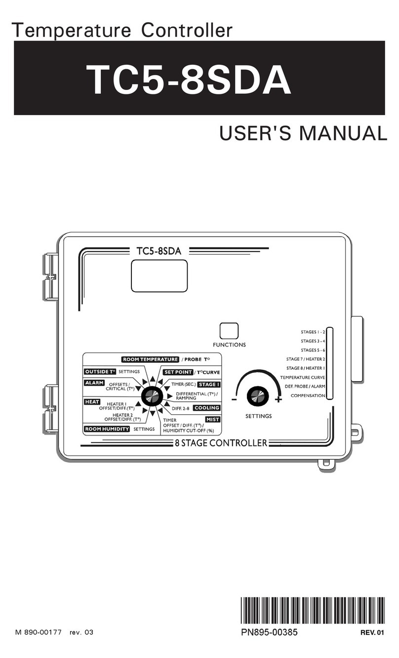
Thevco TC6-2V1SA User manual

7&96
$
7(03(5$785(&21752//(5
USER'S MANUAL
67$786
+80,',7<
2876,'(7(03(5$785(
67$7,&35(6685(
'(,&,1*67$*(
7(03(5$785(&859(
0,1,08063(('&859(
'()(&7,9(352%(
'()(&7,9(327(17,20(7(5
7(03(5$785($/$50
:$7(563,//
23(1
&/26(
0$18$/02'(
&$/,%5$7,21
0,67
+($7(5
/27(03(5$785(29(55,'(
&203(16$7,21
$/$506
92873876
,1/(7
)$167$*(6
&855(17&21',7,216
6(77,1*6
021,725,1*
6(783
52207(03(5$785(
352%(7(03(5$785(
2876,'(7(03(5$785(
5(/$7,9(+80,',7<
67$7,&35(6685(
7,0('$7(
67$*(
67$*(
67$*(
0,67
+($7(5
,1/(7
9287387
9287387
$/$506
:$7(5
+($7(55817,0(
86(5
7(67
6(732,17&859(
0,1,08063(( '&859(
7&96$
7(03(5$785(&21752//(5
M 890-00181 rev. 05 REV. 01

2TC6-2V1SA.rev.05
TABLE OF CONTENTS
PRECAUTIONS ............................................................ 4
FEATURES .................................................................. 5
LOCATION OF THE CONTROLS..................................... 8
INSTALLATION .......................................................... 10
Mounting Instructions ................................................................ 10
Connections ............................................................................. 10
Motor Types ............................................................................ 12
TIME AND DATE FUNCTIONS ..................................... 13
MONITORING FUNCTIONS ......................................... 14
USER SETUP ............................................................. 15
TEMPERATURE SETTINGS ......................................... 23
Displaying Temperatures ............................................................ 23
Temperature Set Points .............................................................. 25
Temperature Curve .................................................................... 26
MINIMUM VENTILATION ............................................ 29
Principle of Operation ................................................................. 29
Stage 1 Minimum Ventilation Settings .......................................... 29
Minimum Ventilation's Speed Curve ............................................. 31
Using Stage 2 Fans for Minimum Ventilation ................................. 34
Low Temperature Override: ......................................................... 34
COOLING .................................................................. 36
Fan Stages Operation ................................................................. 36
Outside Temperature Compensation ............................................. 40
Merging Fan Stages 1 and 2 ....................................................... 43
Merging Stages 2 and 3 ............................................................. 43
De-icing Stage 2 Fans ................................................................ 45
Mist Cooling ............................................................................. 47
Relative Humidity (RH) Compensation .......................................... 50
HEATER SETTINGS .................................................... 54
Heating Stage ........................................................................... 54
Heater Stage's Timers ................................................................ 54

3
TC6-2V1SA.rev.05
TC6-2V1SA
AIR INLET CONTROL.................................................. 57
Principle of Operation ................................................................. 57
Low Temperature Override: ......................................................... 57
Maximum Opening Stage ........................................................... 59
Calibrating the Air Inlet ............................................................... 60
Manual Mode ........................................................................... 61
Static Pressure Compensation ..................................................... 64
0-10V OUTPUTS........................................................ 67
0-10V Outputs: Ventilation Settings ............................................ 68
0-10V Outputs: Heating Settings ................................................ 72
0-10V Outputs: Chimney Damper Settings ................................... 75
ALARM SETTINGS ..................................................... 78
Temperature Alarms: .................................................................. 78
Defective Probe Alarm ................................................................ 80
Defective Potentiometer Alarm ..................................................... 80
Water Spill Alarm ...................................................................... 81
TEST MODE .............................................................. 82
TECHNICAL SPECIFICATIONS .................................... 83
USING THE CONFIGURATION MODULE ....................... 84
INSTALLATION REPORT ............................................. 86
INDEX ...................................................................... 89

4TC6-2V1SA.rev.05
We strongly recommend installing supplementary ventilation as
well as a backup thermostat on at least one fan stage (refer to the
wiring diagram enclosed with this user's manual to connect the
thermostat).
Although overload and overvoltage protection is provided for the
controller circuits, we recommend installing additional protection
devices in the electrical panel.
The room temperature where the controller is located MUST
ALWAYS REMAIN BETWEEN 32°F AND 104°F (0°C TO 40°C).
To avoid exposing the controller to harmful gases or excessive
humidity, it is preferable to install it in a corridor.
DO NOT SPRAY WATER ON THE CONTROLLER
PRECAUTIONS
FOR CUSTOMER USE
Enter the serial number located on
the side of the controller below for
future reference.
Model number:
Serial number:
TC6-2V1SA

5
TC6-2V1SA.rev.05
The TC6-2V1SA is an electronic device used for environmental control in
livestock buildings. It allows the user to maintain a specified target
temperature by controlling the operation of ventilation and heating
equipment. Two stages of variable fans and one stage of either heaters,
mist or ON/OFF fans can be controlled. The main features of the
TC6-2V1SA are as follows:
LCD DISPLAY
An LCD display provides an efficient interface for displaying, monitoring
and adjusting parameter values.
PILOT LIGHTS
Pilot lights indicating the state of outputs allow the user to monitor the
operation of the system without having to enter the building.
REMOVABLE CONNECTORS
The inputs' connection is now made easier by removing the connectors
from the main board.
MINIMUM VENTILATION CYCLE
When ventilation is not required for reducing room temperature, the first
and second fan stages can be operated either continuously or intermit-
tently to reduce the level of humidity and supply oxygen to the room.
TEMPERATURE AND MINIMUM VENTILATION CURVES
The controller can be set to automatically change the temperature set
point and the minimum ventilation cycle over a given period of time, in
accordance with the user's requirements, by specifying a temperature curve
and a minimum ventilation cycle curve with up to ten different points each.
CHOICE OF TEN MOTOR TYPES
The variation in motor speed resulting from a change in voltage will depend
on the make and capacity of the motor. In order to achieve a high degree
of compatibility between controller and motor, the user can choose from
among ten different motor types, thus ensuring that the correct voltage is
supplied.
FEATURES

6TC6-2V1SA.rev.05
TC6-2V1SA
PROBE READINGS RECORDED FOR PAST DAYS
Minimum and maximum readings from temperature probes, static pressure
sensors and humidity sensor are recorded for the current day and the
previous six days.
WATER MONITORING
A pulse input is provided for monitoring water consumption for the current
days and the previous six days.
HEATER RUN TIME MONITORING
Heater run times are kept in memory for the current day and for the previous
6 days.
ALARM MANAGEMENT
Alarms are provided for high-low temperatures, defective probes and other
system functions.
FOUR INDEPENDENT TEMPERATURE PROBE INPUTS
Up to four temperature probes can be connected to the controller in order
to obtain a more accurate reading of the average room temperature and a
faster reaction time.
OUTSIDE TEMPERATURE COMPENSATION
Fan stages are automatically adjusted according to the outside tempera-
ture. It ensures a better stability in the room temperature.
0-10V OUTPUTS
Two 0-10V outputs can be activated to control supplementary ventilation
or heating stages. The 0-10V output can also control chimney dampers.
HUMIDITY COMPENSATION
The minimum speed of stage 1 fans can automatically be adjusted accord-
ing to the humidity level in the barn. Cooling units can also be shut off
when humidity levels are too high.
STATIC PRESSURE CONTROL
A static pressure input is provided to control the static pressure level by
opening and closing the air inlets. When the pressure level is too high, the
inlet opens to compensate. When the pressure level is too low, the air inlet
closes.

7
TC6-2V1SA.rev.05
TC6-2V1SA
CONTROL OF AIR INLET MOVEMENT
The movement of air inlets can be coordinated with the operation of the
fans using a potentiometer located on the panel drive. This allows the air
inlets to be adjusted correctly, without the influence of uncontrollable
factors such as wind or air from adjoining rooms.
PASSWORD PROTECTION
A password allows restricting access to the controller's setup functions.
BACKUP BATTERY
A backup battery allows the unit to keep time in case of a power failure.
OVERLOAD AND OVERVOLTAGE PROTECTION
Resettable fuses are provided at low-voltage inputs and outputs of the
controller to protect its circuitry in the case of an overload or overvoltage.
COMPUTER CONTROL
The controller can be connected to a computer, thus making it possible to
centralize the management of information and diversify control strategies.
TEST MODE
A test mode allows you to simulate temperature changes and verify
controller's performance.

8TC6-2V1SA.rev.05
LOCATION OF THE CONTROLS
LCD DISPLAY
OUTPUT STATUS
MENU SELECT
BUTTONS
FUNCTIONS
ARROW KEYS
67$786
+80,',7<
2876,'(7(03(5$785(
67$7,&35(6685(
'(,&,1*67$*(
7(03(5$785(&859(
0,1,08063(('&859(
'()(&7,9(352%(
'()(&7,9(327(17,20(7(5
7(03(5$785($/$50
:$7(563,//
23(1
&/26(
0$18$/02'(
&$/,%5$7,21
0,67
+($7(5
/27(03(5$785(29(55,'(
&203(16$7,21
$/$506
92873876
,1/(7
)$167$*(6
&855(17&21',7,216
6(77,1*6
021,725,1*
6(783
52207(03(5$785(
352%(7(03(5$785(
2876,'(7(03(5$785(
5(/$7,9(+80,',7<
67$7,&35(6685(
7,0('$7(
67$*(
67$*(
67$*(
0,67
+($7(5
,1/(7
9287387
9287387
$/$506
:$7(5
+($7(55817,0(
86(5
7(67
6(732,17&859(
0,1,08063(('&859(
7&96$
7(03(5$785(&21752//(5

9
TC6-2V1SA.rev.05
TC6-2V1SA
Led Display: The display on the top right corner of the faceplate shows the
current room temperature averaged over all selected room temperature
probes. It can also display the static pressure level or the air inlet position.
LCD Display: The LCD display at the left
shows the current readings and parameters
to be adjusted when you select a function.
The three keys beside the display are used to edit parameters and step
through the display. When the parameters for a given function cannot all
be presented at once on the display, arrows are displayed on the right hand
side to indicate that additional parameters can be displayed using the
arrow keys . After 15 minutes of inactivity, the display returns to the
current temperature display.
Adjustment and navigation arrow keys: The arrow keys that are located
next to the LCD display are used to scroll menus when all parameters
cannot be presented all at once. These keys are also used to modify a
parameter's value once the MODIFY have been pressed.
Status Leds: The status leds that indicates which function is actually
selected.
Adjusting a Parameter: Press on the "MODIFY" button to edit a param-
eter, the parameter will then flash on the display. This means that it can
now be modified. Use the up and down-arrow keys that are located beside
the display to modify the parameter's value.
Output Status LEDs: LEDs at the right side of the control panel give the
status of each output. When the LED is turned on, the output is activated;
when the LED is turned off, the output is deactivated.
Room T° 76.9°F
Pr.Act:1234

10 TC6-2V1SA.rev.05
INSTALLATION
MOUNTING INSTRUCTIONS
Open the latch and lift the cover. Remove the black caps located on each
of the four mounting holes. Mount the enclosure on the wall using four
screws. Be sure the electrical knockouts are at the bottom of the enclo-
sure in order to prevent water from entering the controller. Insert the screws
in the mounting holes and tighten. Fasten the four black caps provided
with the controller onto the four mounting holes. The enclosure must be
mounted in a location that will allow the cover to be completely opened
right up against the wall.
CONNECTIONS
To connect the controller, refer to the wiring diagram enclosed with this
user's manual. Use the electrical knockouts provided at the bottom of the
enclosure. Do not make additional holes in the enclosure, particularly on
the side of the enclosure when using a computer communications module.
Note that the input connectors are now removable. This makes
it easier to connect the different elements to the terminals.
1. PROBES
Probes operate at low voltage and are isolated from the supply.
Be sure that probe cables remain isolated from all high voltage
sources. In particular, do not route the probe cables through the
same electrical knockout as other cables. Do not connect the
shield from the probe cable to a terminal or a ground.
Extending a probe: Each probe can be extended up to 500 feet (150 meters).
To extend a probe:
Use a shielded cable of outside diameter between 0.245 and 0.260 in
(6.22 and 6.60 mm) (the cable dimensions should not be under 18
AWG) to ensure the cable entry is liquid tight. Do not ground the
shielding.
ALL WIRING MUST BE DONE BY AN AUTHORIZED ELECTRI-
CIAN AND MUST COMPLY WITH APPLICABLE CODES,
LAWS AND REGULATIONS. BE SURE POWER IS OFF BEFORE
DOING ANY WIRING TO AVOID ELECTRICAL SHOCKS AND
EQUIPMENT DAMAGE.
!
WARNING

11
TC6-2V1SA.rev.05
TC6-2V1SA
2. ALARM
There are two types of alarms on the
market. One type activates when current
is cut off at its input, whereas the other
activates when current is supplied at its
input. For an alarm of the first type, use
the NC terminal as shown on the wiring
diagram. For an alarm of the second type,
use the NO terminal.
1: 74.2 2:-----
3: 72.3 4:73.0
It is preferable to solder the cable joint to ensure a proper contact
between the two cables.
CAUTION: Do not run probe cables next to other power cables. When
crossing over other cables, cross at 90°.
Defective probes:
An alarm is generated when a defective probe
is detected. To identify the defective probe,
select the PROBE TEMPERATURE or OUT-
SIDE TEMPERATURE function. Dashes are displayed instead of a reading
when the probe is defective. In the case of room temperature probes, the
controller will operate according to the temperature of the remaining probes.
MNO
ALARM
NC
C
NO

12 TC6-2V1SA.rev.05
TC6-2V1SA
MOTOR TYPES
The relationship between the voltage supplied to a motor and its operating
speed is described by a motor curve. This curve varies with the make and
capacity of the motor. The various motors available in the industry have
been divided into ten categories and the controller has been programmed
with a different motor curve for each of these categories. To ensure that
the controller supplies the correct voltages, an appropriate curve must be
selected separately for stages 1 and 2 variable fans, according to the type
of fan motors in use.
Stages 1-2 : Motor Curve Selection:
Select the STAGE 1 or the STAGE 2 function using the menu select
buttons depending on which stage's motor you want to adjust.
Press on the down-arrow key, in order
to select the "Motor curve" screen
display.
Press on the MODIFY button, the motor curve flashes on the display.
Use the arrow keys to adjust the motor curve of the selected stage
then press on the MODIFY button once again to validate.
Motor curve
4

13
TC6-2V1SA.rev.05
TIME AND DATE FUNCTIONS
Set the function to TIME & DATE using the menu select buttons. The
current time and date are displayed.
Press on the MODIFY button. The hours
flash on the display. Use the arrow keys
to set the hours. Press on the MODIFY
button. The minutes flash on the display.
Use the arrow keys to set the minutes. Press on the MODIFY button
once again. The seconds flash on the display. Use the arrow keys to
adjust the seconds to the desired value.
Press on the MODIFY button. The month flashes. Use the arrow keys
to set the month. Press the Modify button. The day flashes. Use the
arrow keys to set the day. Press the Modify button once again, the
year flashes. Use the arrow keys to set the year.
12:00:00 PM
01/01/2003

14 TC6-2V1SA.rev.05
MONITORING FUNCTIONS
1
Viewing Heater Run Times
The controller has an history in which the heater run times , for the past 6
days, are logged in.
Set the function to HEATER RUN TIME
using the menu select buttons.
Note that this function is only available if the
heating stage has been enabled in the USER
SETUP.
The heater's current running time is displayed along with the time and
date.
Keep pressing the down-arrow key to scroll the display. The heater's
run times that have been recorded for the past 6 days are displayed.
2
Viewing Water Consumption
The controller provides a pulse input to monitor the water consumption.
The water consumption is logged into an history for the current day and for
the past 6 days.
Set the function to WATER using the
menu select buttons. Today's water
consumption is displayed.
Note that this function is only available if the
water counter has been enabled in the USER
SETUP.
Press on the down-arrow key to scroll the display. The water
consumption for the past 6 days is displayed.
02/01/02 1:24
01/01/02 2:30
01/31/03 1241l
01/30/03 6189l

15
TC6-2V1SA.rev.05
USER SETUP
The following section describes how to customize the controller for your
particular application. Normally, this setup needs to be done only once. A
template is available at the end of this manual to write down all these
parameters.
It is recommended to clearly define every stage that is going to
be used by your controller. Select the proper stage configuration
on the table below.
1. Set the function to USER using the menu select buttons.
The following parameters are presented below in the order they appear on the
display. The installer's password must first be entered to access these menus. To
modify a parameter, press on the MODIFY button then use the arrow keys to
change it. When you are finished adjusting a parameter, press on the MODIFY
button to validate the new value and to return to the display mode. Press on the
down-arrow key to move to the next parameter.
2. Time of Day Format:
Select the time format:
AM-PM or 24 hours mode.
3. Temperature Units:
Select the temperature units:
Fahrenheit (F°) of Celsius (°C) degrees.
Time ormat
AM-PM
Temp. units
°F
STAGES' DEFINITION TABLE
CHECK THE PROPER STAGE DEFINITION THAT IS GOING TO BE USED BY
YOUR CONTROLLER
1EGATS2EGATS3EGATS
1NOITPO
ELBAIRAV
1NAF
ELBAIRAV
2NAF
RETAEH
2NOITPO
ELBAIRAV
1NAF
ELBAIRAV
2NAF
TSIM
3NOITPO
ELBAIRAV
1NAF
ELBAIRAV
2NAF NAFFFO/NO

16 TC6-2V1SA.rev.05
TC6-2V1SA
4. # of Temperature Sensors in the Room: Set
the total number of temperature sensors
that are wired to the controller. Up to 4
temperature sensors can be selected.
5. Room Probes:
Select which of the room sensors are used
to be part of the average room
temperature. Blinking digits represent
probes that are selected to be part of the
average room temperature. At least one
temperature probe must be selected.
Press on the MODIFY button then set each
probe status by using the arrow keys.
6. Use Water Meter:
Select "Yes" if a water meter is
connected to the controller.
7. Water Meter Units:
Select the water units: Gallons or liters.
This menu is only available if the water meter
has been enabled above.
8. Water Meter Calibration:
Set the # of gallons or liters per pulse.
This menu is only available if the water meter
has been enabled above.
9. Use Humidity Sensor:
Select "Yes" if a relative humidity
sensor is connected to the controller.
10. Humidity Compensation on Min. Speed:
Select "Yes" to enable the compensa-
tion of stage 1 fans' speed, according to
the humidity level (refer to the Relative
Humidity Compensation chapter).
This menu is only available if the humidity
sensor has been enabled above.
Use water meter?
No
Water meter units
lit
Water unit/pulse
1
Use humidity
sensor? No
Rh in luence on
Min. Speed? No
#T° sensors in
the room: 4
Room probes
1234
Room probes
1 On

17
TC6-2V1SA.rev.05
TC6-2V1SA
11. Use Outside Temperature Sensor:
Select "Yes" if an outside temperature
sensor is connected to the unit.
12. Outside T° Compensation on Min. Speed:
Select "Yes" to activate the outside
temperature compensation on the
minimum speed of stage 1 fans (refer to
the Outside T° Compensation chapter).
This menu is only available if the outside
temperature sensor has been enabled above.
13. Use Outside T° Compensation on Stg 1:
Select "Yes" to activate the outside
temperature compensation on stage 1's
# of degrees to 100% (refer to the
Outside T° Compensation chapter).
This menu is only available if the outside
temperature sensor has been enabled above.
14. Use Outside T° Compensation on Stg 2:
Select "Yes" to activate the outside
temperature compensation on stage 2's
# of degrees to 100% (refer to the
Outside T° Compensation chapter).
This menu is only available if the outside
temperature sensor has been enabled above.
15. Winter's Reference Temperature:
Set the temperature that indicates the
beginning of the winter season.
This menu is only available if the
compensation has been enabled on #12, 13
or 14 above) feature has temperature sensor
has been enabled above.
16. Summer's Reference Temperature:
Set the temperature that indicates the
beginning of the summer season.
This menu is only available if the
compensation has been enabled on #12, 13
or 14 above) feature has temperature sensor has been enabled above.
Out T° compens.
stage2 ? No
Outside T° in
winter: 41.0°F
Outside T° in
summer: 59.0°F
Out T° compens.
stage1? No
Use Out T°
sensor? Yes
Out T° compens.
Min Speed? No

18 TC6-2V1SA.rev.05
TC6-2V1SA
17. Use the Static Pressure Sensor:
Select "Yes" if a static pressure sensor
is connected to the controller.
18. Use the Static Pressure Compensation:
Select "Yes" if to activate the static
pressure compensation (refer to the
Static Pressure Compensation chapter).
This menu is only available if the static
pressure sensor has been enabled above.
19. Heating Stage and 0-10V Outputs:
Select "Yes" to enable the heater stage.
Activating the heater stage will automatically
disable the mist stage.
Set the number of 0-10V outputs. Up to
two 0-10V outputs can be used.
20. Use Mist:
Select "Yes" to activate the mist stage.
This menu is only available if the heater stage
has been disabled above.
21. Use Inlet:
Select "Yes" to activate the air inlet
22. Use a timer on the heating stage:
Select "Yes" to activate the heater stage
in a timer mode, according to the room
temperature.
This menu is only available if the heater stage
has been enabled above.
23. Merge between stages 1 and 2:
Select "Yes" if to enable the merge
between fan stages 1&2 (refer to the
"Merge" section of the "Cooling" chapter).
Use Inlet?
Yes
Use Stat. P
sensor? Yes
Use Stat. P
compens.? No
Use Heat? Y e s
#0-10V 2
Use Mist?
Yes
Use heater on
timer ? No
Use merge or
stages 1-2 No

19
TC6-2V1SA.rev.05
TC6-2V1SA
24. Merge between stages 2 and 3:
Select "Yes" if to enable the merge
between fan stages 2 and 3 (refer to
the "Merge" section of the "Cooling"
chapter).
This menu is only shown if stage 3 is used as a fan stage. Refer to the beginning
of this chapter to see if stage 3 is used as a fan stage.
25. De-icing Stage 2:
Select "Yes" if to enable the de-icing
feature on fan stage 2.
26. 0-10V Output # 1 Used for:
Select the proper operation for the first
0-10V output: Ventilation / Heating /
Chimney damper.
This menu is only available if a 0-10V output
has been enabled above.
27. 0-10V #1 follows the Set Point ? :
Select "Yes" if the start temperature of
the first 0-10V output is related to the
set point. This means that when the set
point changes, the start temperature is
adjusted by the same amount. Select "No" to use an absolute start
temperature on this output.
This menu is only available if a 0-10V output has been enabled above.
28. 0-10V or 10-0V Signal:
Select the proper signal of the first
0-10V output (0-10V or 10-0V).
This menu is only available if a 0-10V output
has been enabled above.
29. 0-10V Output # 2 Used for:
Select the proper operation of the
second 0-10V output: Ventilation /
Heating / Chimney damper.
This menu is only available if two 0-10V
outputs have been enabled above.
Use de-icing on
stage 2? No
Use merge or
stages 2-3 No
0-10V 1 used or
Ventilation
0-10V 1 ollows
setpoint? No
0-10V 1 Mode
0-10V
0-10V 2 used or
Heating

20 TC6-2V1SA.rev.05
TC6-2V1SA
30. 0-10V #2 follows the Set Point ? :
Select "Yes" if the start temperature of
the second 0-10V output is related to
the set point. This means that when the
set point changes, the start temperature
is adjusted by the same amount. Select
"No" to use an absolute start tempera-
ture on this output.
This menu is only available if two 0-10V
outputs have been enabled above.
31. 0-10V or 10-0V Signal:
Select the proper signal of the second
0-10V output (0-10V or 10-0V).
This menu is only available if two 0-10V
outputs have been enabled above.
32. Use Night Set Point:
Select "Yes" to enable the night set point.
33. Night Set Point Starts at:
Select the time at which the night set
point starts being used by the controller.
This menu is only available if the night set
point has been enabled above.
34. Day Set Point Starts at:
Select the time at which the day set point
starts being used by the controller.
This menu is only available if the night set
point has been enabled above.
35. Transition Time:
Set the transition time between day and
night set points to the desired value. It
can be adjusted from 15 to 120 minutes.
This menu is only available if the night set point
has been enabled above.
Use night setp?
Yes
Night setp at
8:00P
Day setp at:
7:30A
Transition time
60 min
0-10V 2 ollows
setpoint? No
0-10V 2 Mode
0-10V
Table of contents
Other Thevco Temperature Controllers manuals
Popular Temperature Controllers manuals by other brands
Nibe
Nibe PCM 40 Installer manual
Vaillant
Vaillant VRC 470 installation instructions
Autonics
Autonics TN Series instruction manual
Sentera
Sentera RXTP Series Mounting and operating instructions
Powtier Controls
Powtier Controls TC308 instruction manual

Sterling
Sterling Sterltronic S-Series Service and instruction manual
