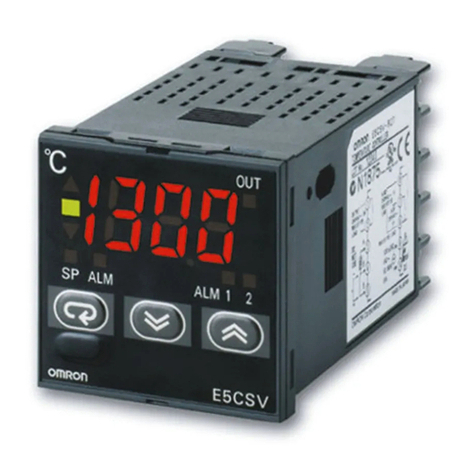
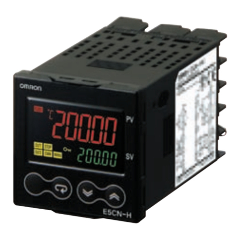
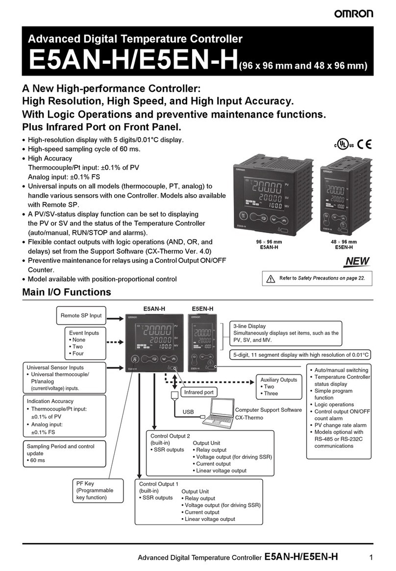
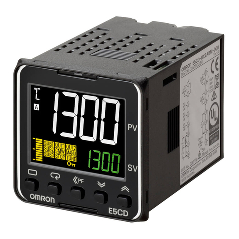
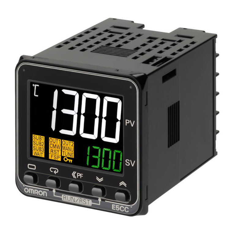
Omron E5CN User manual

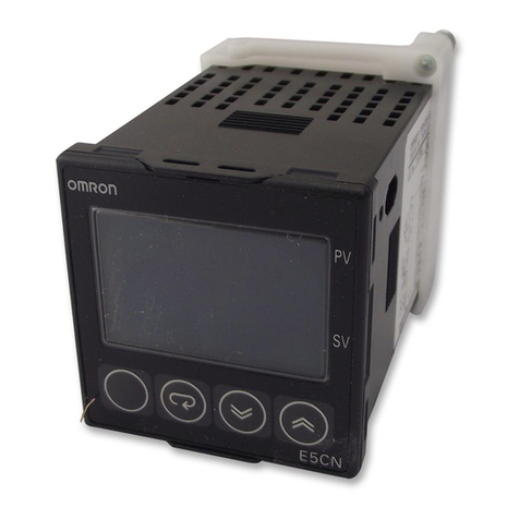
E5CN Temperature Controller
User’s Manual
Revised July 2003

v
Notice:
OMRON products are manufactured for use according to proper procedures by a qualified operator
and only for the purposes described in this manual.
The following conventions are used to indicate and classify precautions in this manual. Always heed
the information provided with them. Failure to heed precautions can result in injury to people or dam-
age to property.
!DANGER Indicates an imminently hazardous situation which, if not avoided, will result in death or
serious injury.
!WARNING Indicates a potentially hazardous situation which, if not avoided, could result in death or
serious injury.
!Caution Indicates a potentially hazardous situation which, if not avoided, may result in minor or
moderate injury, or property damage.
Visual Aids
The following headings appear in the left column of the manual to help you locate different types of
information.
Note Indicates information of particular interest for efficient and convenient opera-
tion of the product.
1,2,3... 1. Indicates lists of one sort or another, such as procedures, checklists, etc.

vi
Conventions Used in This Manual
Meanings of Abbreviations
The following abbreviations are used in parameter names, figures and in text explanations. These
abbreviations mean the following:
Note “EU” stands for Engineering Unit. EU is used as the minimum unit for engi-
neering units such as °C, m, and g.
The size of EU varies according to the input type. For example, when the input
temperature setting range is –200 to +1300°C, 1 EU is 1°C, and when the
input temperature setting range is –20.0 to +500.0°C, 1 EU is 0.1°C.
In the case of analog input, the size of EU varies according to the decimal
point position of the scaling setting, and 1 EU becomes the minimum scaling
unit.
How to Read Display Symbols
The following tables show the correspondence between the symbols displayed on the displays and
alphabet characters.
Symbol Term
PV Process value
SP Set point
AT Auto-tuning
ST Self-tuning
EU Engineering unit (See note.)
ABCDEFGHI JKLM
NOPQRSTUVWXYZ
OMRON, 1998
All rights reserved. No part of this publication may be reproduced, stored in a retrieval system, or transmitted, in any form, o
r
by any means, mechanical, electronic, photocopying, recording, or otherwise, without the prior written permission o
f
OMRON.
No patent liability is assumed with respect to the use of the information contained herein. Moreover, because OMRON is con-
stantly striving to improve its high-quality products, the information contained in this manual is subject to change without
notice. Every precaution has been taken in the preparation of this manual. Nevertheless, OMRON assumes no responsibility
for errors or omissions. Neither is any liability assumed for damages resulting from the use of the information contained in
this publication.

vii
TABLE OF CONTENTS
PRECAUTIONS . . . . . . . . . . . . . . . . . . . . . . . . . . . . . . . . . . . xi
1 Preface . . . . . . . . . . . . . . . . . . . . . . . . . . . . . . . . . . . . . . . . . . . . . . . . . . . . . . . . . . . . . . . . . . xii
2 Precautions. . . . . . . . . . . . . . . . . . . . . . . . . . . . . . . . . . . . . . . . . . . . . . . . . . . . . . . . . . . . . . . xii
3 Safety Precautions . . . . . . . . . . . . . . . . . . . . . . . . . . . . . . . . . . . . . . . . . . . . . . . . . . . . . . . . . xii
SECTION 1
INTRODUCTION . . . . . . . . . . . . . . . . . . . . . . . . . . . . . . . . . 1
1-1 Names of Parts. . . . . . . . . . . . . . . . . . . . . . . . . . . . . . . . . . . . . . . . . . . . . . . . . . . . . . . . . . . . 2
1-2 I/O Configuration and Main Functions . . . . . . . . . . . . . . . . . . . . . . . . . . . . . . . . . . . . . . . . . 3
1-3 How Setup Levels Are Configured and Operating the Keys on the Front Panel. . . . . . . . . . 5
1-4 Communications Function. . . . . . . . . . . . . . . . . . . . . . . . . . . . . . . . . . . . . . . . . . . . . . . . . . . 7
SECTION 2
PREPARATIONS. . . . . . . . . . . . . . . . . . . . . . . . . . . . . . . . . . 9
2-1 Installation . . . . . . . . . . . . . . . . . . . . . . . . . . . . . . . . . . . . . . . . . . . . . . . . . . . . . . . . . . . . . . . 10
2-2 Wiring Terminals. . . . . . . . . . . . . . . . . . . . . . . . . . . . . . . . . . . . . . . . . . . . . . . . . . . . . . . . . . 12
2-3 Requests at Installation . . . . . . . . . . . . . . . . . . . . . . . . . . . . . . . . . . . . . . . . . . . . . . . . . . . . . 16
SECTION 3
BASIC OPERATION. . . . . . . . . . . . . . . . . . . . . . . . . . . . . . . 17
3-1 Initial Setup Examples. . . . . . . . . . . . . . . . . . . . . . . . . . . . . . . . . . . . . . . . . . . . . . . . . . . . . . 18
3-2 Setting the Input Type . . . . . . . . . . . . . . . . . . . . . . . . . . . . . . . . . . . . . . . . . . . . . . . . . . . . . . 20
3-3 Selecting ×C/×F. . . . . . . . . . . . . . . . . . . . . . . . . . . . . . . . . . . . . . . . . . . . . . . . . . . . . . . . . . . 21
3-4 Selecting PID Control or ON/OFF Control. . . . . . . . . . . . . . . . . . . . . . . . . . . . . . . . . . . . . . 22
3-5 Setting Output Specifications . . . . . . . . . . . . . . . . . . . . . . . . . . . . . . . . . . . . . . . . . . . . . . . .23
3-6 Setting the SP. . . . . . . . . . . . . . . . . . . . . . . . . . . . . . . . . . . . . . . . . . . . . . . . . . . . . . . . . . . . . 25
3-7 Executing ON/OFF Control. . . . . . . . . . . . . . . . . . . . . . . . . . . . . . . . . . . . . . . . . . . . . . . . . . 26
3-8 Determining PID Constants (AT, ST, manual setup). . . . . . . . . . . . . . . . . . . . . . . . . . . . . . . 28
3-9 Alarm Outputs . . . . . . . . . . . . . . . . . . . . . . . . . . . . . . . . . . . . . . . . . . . . . . . . . . . . . . . . . . . . 32
3-10 Heater Burnout Alarm (HBA) . . . . . . . . . . . . . . . . . . . . . . . . . . . . . . . . . . . . . . . . . . . . . . . . 35
3-11 Requests during Operation . . . . . . . . . . . . . . . . . . . . . . . . . . . . . . . . . . . . . . . . . . . . . . . . . .38
SECTION 4
Applied Operation . . . . . . . . . . . . . . . . . . . . . . . . . . . . . . . . . 39
4-1 Shifting Input Values . . . . . . . . . . . . . . . . . . . . . . . . . . . . . . . . . . . . . . . . . . . . . . . . . . . . . . . 40
4-2 Alarm Hysteresis . . . . . . . . . . . . . . . . . . . . . . . . . . . . . . . . . . . . . . . . . . . . . . . . . . . . . . . . . . 44
4-3 Setting Scaling Upper and Lower Limits (analog input). . . . . . . . . . . . . . . . . . . . . . . . . . . . 46
4-4 Executing Heating and Cooling Control . . . . . . . . . . . . . . . . . . . . . . . . . . . . . . . . . . . . . . . . 47
4-5 To Use Event Input . . . . . . . . . . . . . . . . . . . . . . . . . . . . . . . . . . . . . . . . . . . . . . . . . . . . . . . . 49
4-6 Setting the SP Upper and Lower Limit Values . . . . . . . . . . . . . . . . . . . . . . . . . . . . . . . . . . . 53
4-7 Executing the SP Ramp Function (limiting the SP change rate). . . . . . . . . . . . . . . . . . . . . . 55

viii
TABLE OF CONTENTS
4-8 To Move to the Advanced Function Setting Level . . . . . . . . . . . . . . . . . . . . . . . . . . . . . . . . 57
4-9 Using the Key Protect Level . . . . . . . . . . . . . . . . . . . . . . . . . . . . . . . . . . . . . . . . . . . . . . . . .58
4-10 To Use PV Color Change Function. . . . . . . . . . . . . . . . . . . . . . . . . . . . . . . . . . . . . . . . . . . . 59
SECTION 5
Parameters. . . . . . . . . . . . . . . . . . . . . . . . . . . . . . . . . . . . . . . . 61
5-1 Conventions Used in this Section . . . . . . . . . . . . . . . . . . . . . . . . . . . . . . . . . . . . . . . . . . . . . 62
5-2 Protect Level . . . . . . . . . . . . . . . . . . . . . . . . . . . . . . . . . . . . . . . . . . . . . . . . . . . . . . . . . . . . . 63
5-3 Operation Level . . . . . . . . . . . . . . . . . . . . . . . . . . . . . . . . . . . . . . . . . . . . . . . . . . . . . . . . . . . 65
5-4 Adjustment Level. . . . . . . . . . . . . . . . . . . . . . . . . . . . . . . . . . . . . . . . . . . . . . . . . . . . . . . . . . 71
5-5 Initial Setting Level . . . . . . . . . . . . . . . . . . . . . . . . . . . . . . . . . . . . . . . . . . . . . . . . . . . . . . . . 79
5-6 Advanced Function Setting Level . . . . . . . . . . . . . . . . . . . . . . . . . . . . . . . . . . . . . . . . . . . . . 88
5-7 Communication Setting Level . . . . . . . . . . . . . . . . . . . . . . . . . . . . . . . . . . . . . . . . . . . . . . . . 105
SECTION 6
Calibration. . . . . . . . . . . . . . . . . . . . . . . . . . . . . . . . . . . . . . . . 107
6-1 Parameter Structure . . . . . . . . . . . . . . . . . . . . . . . . . . . . . . . . . . . . . . . . . . . . . . . . . . . . . . . . 108
6-2 User Calibration. . . . . . . . . . . . . . . . . . . . . . . . . . . . . . . . . . . . . . . . . . . . . . . . . . . . . . . . . . . 109
6-3 Calibrating Thermocouples . . . . . . . . . . . . . . . . . . . . . . . . . . . . . . . . . . . . . . . . . . . . . . . . . . 110
6-4 Calibrating Analog Input. . . . . . . . . . . . . . . . . . . . . . . . . . . . . . . . . . . . . . . . . . . . . . . . . . . . 113
6-5 Calibrating Platinum Resistance Thermometers . . . . . . . . . . . . . . . . . . . . . . . . . . . . . . . . . . 114
6-6 Checking Indication Accuracy . . . . . . . . . . . . . . . . . . . . . . . . . . . . . . . . . . . . . . . . . . . . . . . 115
Appendices . . . . . . . . . . . . . . . . . . . . . . . . . . . . . . . . . . . . . . . 117
Index. . . . . . . . . . . . . . . . . . . . . . . . . . . . . . . . . . . . . . . . . . . . . 133
Revision History . . . . . . . . . . . . . . . . . . . . . . . . . . . . . . . . . . . 135

ix
About this Manual:
Please read this manual carefully and be sure you understand the information provided before
attempting to install or operate the E5CN Temperature Controller. Be sure to read the precautions pro-
vided in the following section.
Precautions provides general precautions for using the E5CN Temperature Controller.
Section 1 describes the features, names of parts and typical functions.
Section 2 describes installation and wiring.
Section 3 describes basic control examples.
Section 4 describes advanced functions to fully use E5CN.
Section 5 describes advanced functions to fully use E5CN.
Section 6 describes calibration method.
!WARNING Failure to read and understand the information provided in this manual may result in per-
sonal injury or death, damage to the product, or product failure. Please read each section
in its entirety and be sure you understand the information provided in the section and
related sections before attempting any of the procedures or operations given.

xi
PRECAUTIONS
This section provides general precautions for using the E5CN Temperature Controller.
The information contained in this section is important for the safe and reliable application of the E5CN
Temperature Controller. You must read this section and understand the information contained before attempting
to set up or operate a Temperature Controller.
1 Preface. . . . . . . . . . . . . . . . . . . . . . . . . . . . . . . . . . . . . . . . . . . . . . . . . . . . . . . xii
2 Precautions . . . . . . . . . . . . . . . . . . . . . . . . . . . . . . . . . . . . . . . . . . . . . . . . . . . xii
3 Safety Precautions. . . . . . . . . . . . . . . . . . . . . . . . . . . . . . . . . . . . . . . . . . . . . . xii
3-1 Safety Signal Words . . . . . . . . . . . . . . . . . . . . . . . . . . . . . . . . . . . . . xii
3-2 Safety Precautions . . . . . . . . . . . . . . . . . . . . . . . . . . . . . . . . . . . . . . xiii
3-3 Notice . . . . . . . . . . . . . . . . . . . . . . . . . . . . . . . . . . . . . . . . . . . . . . . . xiii

xii
Preface 1
1 Preface
The compact temperature controller E5CN allows the user to carry out the fol-
lowing:
• Select from many types of temperature, infrared temperature sensor and
analog input
• Select heating and cooling control in addition to standard control
• Select AT (auto-tuning) and ST (self-tuning) as tuning functions
• Use multi-SP and the run/stop function according to event input
• Use the HBA (heater burnout alarm) function (when option board E53-
CNHB or E53-CNH03 is fitted)
• Use the communications function (when option communications unit E53-
CNH03 is fitted)
• Calibrate sensor input
• The E5CN features a watertight construction (NEMA4X : equivalent to
IP66).
• The E5CN conforms to UL/CSA/ICE safety standards and EMC stan-
dards.
• Control process condition can be checked visually by PV color change
function.
This User’s Manual describes how to use the E5CN.
Before using your E5CN, thoroughly read and understand this manual in order
to ensure correct use.
Also, store this manual in a safe place so that it can be retrieved whenever
necessary.
Note For an additional description of the communications function, also refer to the
E5AN/EN/CN/GN Temperature Controller, Communications Function User’s
Manuals (Cat. No. H102)
2 Precautions
When the product is used under the circumstances or environment described
in this manual, always adhere to the limitations of the rating and functions.
Also, for safety, take countermeasures such as fitting fail safe installations.
DO NOT USE :
• In circumstances or environments that have not been described below in
this manual.
• For control in nuclear power, railway, aircraft, vehicle, incinerator, medical,
entertainment, or safety applications.
• Where death or serious property damage may occur, or where extensive
safety precautions are required.
3 Safety Precautions
3-1 Safety Signal Words
This manual uses the following signal words to mark safety precautions for the
E5CN.
These precautions provide important information for the safe application of
the product. You must be sure to follow the instructions provided in all safety
precautions.

xiii
Safety Precautions 3
!WARNING Indicates information that, if not heeded, could possibly result in loss of life or
serious injury.
!Caution Indicates information that, if not heeded, could result in relatively serious or
minor injury, damage to the product, or faulty operation.
3-2 Safety Precautions
!Caution Electric Shock Warning
Do not touch the terminals while the power is ON.
Doing so may cause an electric shock.
!Caution Do not allow metal fragments or lead wire scraps to fall inside this product.
These may cause electric shock, fire or malfunction.
!Caution Never disassemble, repair or modify the product.
Doing so may cause electric shock, fire or malfunction.
!Caution Do not use the product in flammable and explosive gas atmospheres.
!Caution The life expectancy of the output relays varies greatly with the switching
capacity and other switching conditions. Always use the output relays within
their rated load and electrical life expectancy. If an output relay is used beyond
its life expectancy, its contacts may become fused or burned.
!Caution Use the product within the rated load.
Not doing so may cause damage or fire.
!Caution Use this product within the rated supply voltage.
Not doing so may cause damage or fire.
!Caution Tighten the terminal screws properly. Tighten them to a torque of 0.74 N⋅m
(7.5kgf⋅cm)(max.)
Loose screws may cause malfunction.
!Caution Set all settings according to the control target of the product.
If the settings are not appropriate for the control target, the product may oper-
ate in an unexpected manner, resulting in damage to the product or resulting
in accidents.
!Caution To maintain safety in the event of a product malfunction, always take appropri-
ate safety measures, such as installing an alarm on a separate line to prevent
excessive temperature rise.
If a malfunction prevents proper control, a major accident may result.
3-3 Notice
Be sure to observe these precautions to ensure safe use.
1. Do not wire unused terminals.
2. Be sure to wire properly with correct polarity of terminals.

xiv
Safety Precautions 3
3. To reduce induction noise, separate the high-voltage or large-current pow-
er lines from other lines, and avoid parallel or common wiring with the pow-
er lines when you are wiring to the terminals. We recommend using
separating pipes, ducts, or shielded lines.
4. Do not use this product in the following places:
• Places subject to dust or corrosive gases (in particular, sulfide gas and
ammonia gas)
• Places subject to high humidity, condensation or freezing
• Places subject to direct sunlight
• Places subject to vibration and large shocks
• Places subject to splashing liquid or oily atmosphere
• Places directly subject to heat radiated from heating equipment
• Places subject to intense temperature changes
5. To allow heat to escape, do not block the area around the product. (Ensure
that enough space is left for the heat to escape.)
• Do not block the ventilation holes on the casing.
6. When you draw out the internal mechanism from the housing, never touch
electric components inside or subject the internal mechanism to shock.
7. Cleaning: Do not use paint thinner or the equivalent. Use standard grade
alcohol to clean the product.
8. Use specified size (M3.5, width 7.2 mm or less) crimped terminals for wir-
ing.
9. Allow as much space as possible between the E5CN and devices that gen-
erate powerful high-frequency noise (e.g. high-frequency welders, high-
frequency sewing machines) or surges.
10. When executing self-tuning, turn the load (e.g. heater) ON simultaneously
or before you turn the E5CN ON. If you turn the E5CN ON before turning
the load ON, correct self-tuning results and optimum control may no longer
be obtained.
11. Use a 100 to 240 VAC (50/60 Hz), 24 VAC (50/60 Hz) or 24 VDC power
supply matched to the power specifications of the E5CN. Also, make sure
that rated voltage is attained within two seconds of turning the power ON.
12. Attach a surge suppresser or noise filter to peripheral devices that gener-
ate noise (in particular, motors, transformers, solenoids, magnetic coils or
other equipment that have an inductance component).
13. When mounting a noise filter on the power supply, be sure to first check the
filter’s voltage and current capacity, and then mount the filter as close as
possible to the E5CN.
14. Use within the following temperature and humidity ranges:
• Temperature: -10 to 55°C, Humidity: 25 to 85% (with no icing or conden-
sation)
If the E5CN is installed inside a control board, the ambient temperature
must be kept to under 55°C, including the temperature around the E5CN.
If the E5CN is subjected to heat radiation, use a fan to cool the surface of
the E5CN to under 55°C.
15. Store within the following temperature and humidity ranges:
• Temperature: -25 to 65°C, Humidity: 25 to 85% (with no icing or conden-
sation)
16. Never place heavy objects on, or apply pressure to the E5CN as it may
cause it to deform and deteriorate during use or storage.
17. Avoid using the E5CN in places near a radio, television set, or wireless in-
stallation. These devices can cause radio disturbances which adversely af-
fect the performance of the E5CN.
1
SECTION 1
INTRODUCTION
1-1 Names of Parts . . . . . . . . . . . . . . . . . . . . . . . . . . . . . . . . . . . . . . . . . . . . . . . . 2
1-1-1 Front panel . . . . . . . . . . . . . . . . . . . . . . . . . . . . . . . . . . . . . . . . . . . . 2
1-1-2 Display . . . . . . . . . . . . . . . . . . . . . . . . . . . . . . . . . . . . . . . . . . . . . . . 2
1-1-3 How to use keys . . . . . . . . . . . . . . . . . . . . . . . . . . . . . . . . . . . . . . . . 3
1-2 I/O Configuration and Main Functions. . . . . . . . . . . . . . . . . . . . . . . . . . . . . . 3
1-2-1 I/O configuration . . . . . . . . . . . . . . . . . . . . . . . . . . . . . . . . . . . . . . . 3
1-2-2 Main functions . . . . . . . . . . . . . . . . . . . . . . . . . . . . . . . . . . . . . . . . . 4
1-3 How Setup Levels Are Configured and Operating the Keys on the Front Panel 5
1-3-1 Selecting parameters. . . . . . . . . . . . . . . . . . . . . . . . . . . . . . . . . . . . . 7
1-3-2 Fixing settings. . . . . . . . . . . . . . . . . . . . . . . . . . . . . . . . . . . . . . . . . . 7
1-4 Communications Function . . . . . . . . . . . . . . . . . . . . . . . . . . . . . . . . . . . . . . . 7

2
Names of Parts Section 1-1
1-1 Names of Parts
1-1-1 Front panel
1-1-2 Display
No. 1 display Displays the process value or parameter type.
No. 2 display Displays the set point, manipulated variable or set value (setup) of the param-
eter.
Operation indicators 1. ALM1 (alarm 1)
Lights when alarm 1 output is ON.
ALM2 (alarm 2)
Lights when alarm 2 output is ON.
2. HB (heater burnout alarm display)
Lights when a heater burnout is detected.
3. OUT1, 2 (control output 1, control output 2)
Lights when control output 1 and/or control output 2 are ON.
Note, however, that OUT1 is out at all times when control output 1 is current output.
4. STOP (stop)
Lights when control of the E5CN has been stopped.
During control, this indicator lights when an event or the run/stop function has be-
come stopped. Otherwise, this indicator is out.
5. CMW (communications writing control)
Lights when communications writing is “enabled” and is out when it is “disabled.”
Temperature unit The temperature unit is displayed when the display unit parameter is set to a
temperature. Indication is determined by the currently selected “temperature
unit” parameter set value. When this parameter is set to “°C”, “c” is displayed,
and when set to “°F”, “f” is displayed.
No.1 display
No.2 display
Up key
Down key
Mode key
Level key
Temperature
unit
Operation
indicators

3
I/O Configuration and Main Functions Section 1-2
1-1-3 How to use keys
The following describes the basic functions of the front panel keys.
(level) key Press this key to select the setting levels. The setting level is selected in order
“operation level” ←→ “adjustment level”, “initial setting level” ←→ “communi-
cations setting level”.
(mode) key Press this key to select parameters within each level.
(up) key Each press of this key increments values displayed on the No.2 display. Hold-
ing down this key continuously increments values.
(down) key Each press of this key decrements values displayed on the No.2 display. Hold-
ing down this key continuously decrements values.
+ key
combination This key combination sets the E5CN to the “protect level.” For details on the
protect level, see Section 5 Parameters.
1-2 I/O Configuration and Main Functions
1-2-1 I/O configuration
E5CN
*HBA CT input
Controller
Control output 1
Control output 2
Standard
Alarm 2
Alarm 1
HBA
Input error
Alarm output 2
Alarm output 1
OUT1
OUT2
ALM2
ALM1
HB
Event input 2ch
Control output 1
*
*
"*" marked items are options.
Temperature
input/analog input
SP input from external
digital switch function
andRun/Stop function
Heating
and cooling
Communications
function

4
I/O Configuration and Main Functions Section 1-2
1-2-2 Main functions
The following introduces the main functions of the E5CN. For details on each
function and how to use the functions, see Section 3 onwards.
Input sensor types • The following input sensors can be connected for temperature input:
Thermocouple : K, J, T, E, L, U, N, R, S, B
Infrared temperature sensor type : ES1A
: K(10 to 70°C), K(60 to 120°C),
K(115 to 165°C), K (160 to 260°C)
Platinum resistance thermometer
: Pt100, JPt100
Analog input : 0 to 50 mV
Control output • Control output is either relay, voltage output or current output depending
on the model of E5CN.
• If you select heating and cooling control on the E5CN-@2@@, alarm 2
output is used as cooling side output. So, use alarm 1 if an alarm is
needed in heating and cooling control.
Alarms • Alarms are supported on the E5CN-@2@@. Set the alarm type and alarm
value, or upper- and lower-limit alarms.
• If necessary, a more comprehensive alarm function can be achieved by
setting the “standby sequence”, “alarm hysteresis”, “close in alarm/open
in alarm” and Alarm latch ON/OFF parameters.
• When the input error output is set to “ON”, alarm output 1 turns ON when
an input error occurs.
Control adjustment • Optimum PID constants can be set easily by AT (auto-tuning) and ST
(self-tuning).
Event input • When the option event input unit E53-CNHB is mounted in the E5CN, the
following functions can be achieved by event input:
Set point selection (multi-SP max. 4 points) and run/stop
HBA • The heater burnout alarm (HBA) function is supported when the option
unit (E53-CNHB or E53-CNH03) is mounted in the E5CN.
Communications function • Communications according to CompoWay/F* and Sysway are supported
when the option communications unit E53-CNH03 is mounted in the
E5CN.
Communications are carried out over the RS-485 interface.
Note CompoWay/F is a general-purpose serial communications-based unified com-
munications procedure developed by OMRON. CompoWay/F uses com-
mands compliant with the well-established FINS, together with a unified frame
format on OMRON programmable controllers to facilitate communications
between personal computers and components.

5
How Setup Levels Are Configured and Operating the Keys on the Front Panel Section 1-3
1-3 How Setup Levels Are Configured and Operating the Keys
on the Front Panel
Parameters are divided into groups, each called a “level”. Each of the set val-
ues (setup items) in these levels are called a “parameter.” The parameters on
the E5CN are divided into the following seven levels:
: Indicates items that can be set.
Of these levels, the initial setting level, communications setting level,
advanced function setting level and calibration level can be used only when
control has stopped. Note that controller outputs are stopped when any of
these four levels are selected.
Control in
Progress Control Stopped
Protect level -
Operation level -
Adjustment level -
Initial setting level -
Advanced function setting level -
Calibration level -
Communications setting level -
Password input
set value "1201"
Advanced
function setting level
Calibration level
Password input
set value "-169"
Control stops.
Initial setting level
Less than
1 second
key
key
Commu-
nications
setting level
The PV display flashes after one second.
Power ON
Operation level
1 second min.
Protect level
Control in progress
Control stopped
Adjustment level
Less than
1 second
key
1 second min.
key
1 second min.
key
3 seconds min.key
Note :
Communications setting level is displayed
when the optional communication unit
E53-CNH03 is mounted.
3 seconds min.
+ key
The PV display
flashes
25
100
25
100
+ key
+ key

6
How Setup Levels Are Configured and Operating the Keys on the Front Panel Section 1-3
Protect level • To move the mode at this level, simultaneously press the and
keys for at least three seconds in the operation level or adjustment level.
This level is for preventing unwanted or accidental modification of param-
eters. Protected levels will not be displayed, and so the parameters in that
level cannot be modified.
Operation level • This level is displayed when you turn the power ON. You can move to the
protect level, initial setting level and adjustment level from this level.
• Normally, select this level during operation. During operation, the process
value, set point and manipulated variable can be monitored, and the
alarm value and upper- and lower-limit alarms can be monitored and
modified.
Adjustment level • To move the mode at this level, press the key for less than one sec-
ond.
• This level is for entering set values and offset values for control. This level
contains parameters for setting the AT (auto-tuning), communications
writing enable/disable, hysteresis, multi-SP, input shift values, heater
burnout alarm (HBA) and PID constants. You can move to the top param-
eter of the initial setting level and operation level from here.
Initial setting level • To move the mode at this level, press the key for at least three sec-
onds in the operation level or adjustment level. The PV display flashes
after one second. This level is for specifying the input type, selecting the
control method, control period, setting direct/reverse action and alarm
type. You can move to the advanced function setting level or communica-
tions setting level from this level. To return to the operation level, press the
key for at least one second. To move to the communications setup
level, press the key for less than one second.
Advanced function setting
level • To select this level, you must enter the password (“-169”) in the initial set-
ting level.
• You can move to the calibration level only from this level.
• This level is for setting the automatic return of display mode, MV limitter,
event input assignment, standby sequence, alarm hysteresis, ST (self-
tuning) and for moving to the user calibration level.
Communications setting
level • To move the mode at this level, press the key for less than one sec-
ond in the initial setting level. When the communications function is used,
set the communications conditions in this level. Communicating with a
personal computer (host computer) allows set points to be read and writ-
ten, and manipulated variables to be monitored.
Note This level is available if communications card (E53-CNH03) is fitted
to the unit.
Calibration level • To move the mode at this level, you must enter the password “1201” in the
advanced function setting level. This level is for offsetting deviation in the
input circuit.
• You cannot move to other levels by operating the keys on the front panel
from the calibration level. To cancel this level, turn the power OFF then
back ON again.

7
Communications Function Section 1-4
1-3-1 Selecting parameters
• To select parameters in each level, press the key. Each press of the
key advances to the next parameter. For details on each parameter,
see Section 5.
1-3-2 Fixing settings
• If you press the key at the final parameter, the display returns to the
top parameter for the current level.
• To change parameter settings or setup, specify the setting using the
or keys, and either leave the setting for at least two seconds or press
the key. This fixes the setting.
• When another level is selected, the parameter and setting on the display
are fixed.
• When you turn the power OFF, you must first fix the settings or parameter
setup (by pressing the key). The settings and parameter setup are
sometimes not changed by merely pressing the or keys.
1-4 Communications Function
The E5CN can be provided with a communications function that allows you to
check and set controller parameters on a host computer. If the communica-
tions function is required, mount the option unit E53-CNH03 in the E5CN. For
details on the communications function, see the separate “Communications
Functions User’s Manual.”
Follow the procedure below to move to the communications setting level.
1,2,3... 1. Press the key for at least three seconds in the “operation level”. The
level moves to the “initial setting level”.
2. Press the key for less than one second. The “initial setting level”
moves to the “communications setting level”.
Parameter
1
Parameter
2
Parameter
3
Parameter
n

8
Communications Function Section 1-4
3. Pressing the key advances the parameters as shown in the following
figure.
4. Press the or keys to change the parameter setups.
Setting up
communications data Set the E5CN communications specifications so that they match the commu-
nications setup of the host computer.
Communications unit No.
Baud rate
Data bit
Stop bit
Parity
Parameter Displayed
Characters Set (monitor) Value Settings Default Unit
Communications unit No. A:; 0 to 99 1 None
Baud rate .<? 1.2, 2.4, 4.8, 9.6, 19.2 ,, , ,
9.6 kbps
Data bit 81: 7, 8 7 bit
Stop bit ?.5@ 1, 2 2 bit
Parity <>@E None, even, odd :;:1,1B1:,;00 Even None

9
SECTION 2
PREPARATIONS
2-1 Installation. . . . . . . . . . . . . . . . . . . . . . . . . . . . . . . . . . . . . . . . . . . . . . . . . . . . 10
2-1-1 Dimensions. . . . . . . . . . . . . . . . . . . . . . . . . . . . . . . . . . . . . . . . . . . . 10
2-1-2 Panel cutout . . . . . . . . . . . . . . . . . . . . . . . . . . . . . . . . . . . . . . . . . . . 10
2-1-3 Setting up the option units . . . . . . . . . . . . . . . . . . . . . . . . . . . . . . . . 11
2-1-4 Mounting. . . . . . . . . . . . . . . . . . . . . . . . . . . . . . . . . . . . . . . . . . . . . . 12
2-2 Wiring Terminals. . . . . . . . . . . . . . . . . . . . . . . . . . . . . . . . . . . . . . . . . . . . . . . 12
2-2-1 Terminal arrangement. . . . . . . . . . . . . . . . . . . . . . . . . . . . . . . . . . . . 12
2-2-2 Precautions when wiring. . . . . . . . . . . . . . . . . . . . . . . . . . . . . . . . . . 13
2-2-3 Wiring. . . . . . . . . . . . . . . . . . . . . . . . . . . . . . . . . . . . . . . . . . . . . . . . 13
2-3 Requests at Installation . . . . . . . . . . . . . . . . . . . . . . . . . . . . . . . . . . . . . . . . . . 16
2-3-1 To ensure prolonged use. . . . . . . . . . . . . . . . . . . . . . . . . . . . . . . . . . 16
2-3-2 To reduce the influence of noise. . . . . . . . . . . . . . . . . . . . . . . . . . . . 16
2-3-3 To ensure high-precision measurement . . . . . . . . . . . . . . . . . . . . . . 16

10
Installation Section 2-1
2-1 Installation
2-1-1 Dimensions
E5CN (Unit: mm)
2-1-2 Panel cutout
(Unit: mm)
• Insert the controller through the hole in the panel from the front, and push
the adapter on from the rear. Push the adapter up to the back of the panel
ensuring that the controller is pushed all the way in, removing any gap
between the controller, panel and adapter. Finally use the two screws on
the adapter to secure the unit in place.
• To mount the E5CN so that it is waterproof, insert the waterproof packing
onto the E5CN. The E5CN cannot be waterproofed when the E5CN is
group-mounted.
• The recommended panel thickness is 1 to 5 mm.
• Maintain the specified mounting space between each controller. Control-
lers must not be closely mounted vertically.
• When two or more E5CNs are mounted, make sure that the surrounding
temperature does not exceed the allowable operating temperature given
in the specifications.
• The E5CN-@-500 is provided with a terminal cover.
48 × 48
E5CN
978 93
102
58
48.8
1
2
3
4
5
11
12
13
14
15
6
7
8
9
10
44.8 × 44.8
(48 × number of units -2.5)
When mounted separately When group-mounted +1.0
0
45 +0.6
0
60 min.
45+0.6
0
45 +0.6
0
Other manuals for E5CN
7
Table of contents
Other Omron Temperature Controllers manuals