Thies CLIMA Compact WSC10 User manual
Weather Station Compact WSC10
Instructions for Use
4.9042.00.00x
Softwareversion: V00.07 Stand: 02/2023
Dok. No. 022028/02/23
T H E W O R L D O F W E A T H E R D A T A
© Adolf Thies GmbH & Co. KG · Hauptstraße 76 · 37083 Göttingen · Germany 022028/02/23
Phone +49 551 79001-0 · Fax +49 551 79001-65 · inf[email protected] ·www.thiesclima.com Page 2 of 40
Safety Instructions
•Before operating with or at the device/product, read through the operating instructions.
This manual contains instructions which should be followed on mounting, start-up, and operation.
A non-observance might cause:
- failure of important functions
- endangerment of persons by electrical or mechanical effect
- damage to objects
•Mounting, electrical connection and wiring of the device/product must be carried out only by a qualified
technician who is familiar with and observes the engineering regulations, provisions and standards
applicable in each case.
•Repairs and maintenance may only be carried out by trained staff or Adolf Thies GmbH & Co. KG. Only
components and spare parts supplied and/or recommended by Adolf Thies GmbH & Co. KG should be
used for repairs.
•Electrical devices/products must be mounted and wired only in a voltage-free state.
•Adolf Thies GmbH & Co KG guarantees proper functioning of the device/products provided that no
modifications have been made to the mechanics, electronics or software, and that the following points
are observed:
•All information, warnings and instructions for use included in these operating instructions must be taken
into account and observed as this is essential to ensure trouble-free operation and a safe condition of
the measuring system / device / product.
•The device / product is designed for a specific application as described in these operating instructions.
•The device / product should be operated with the accessories and consumables supplied and/or
recommended by Adolf Thies GmbH & Co KG.
•Recommendation: As it is possible that each measuring system / device / product may, under certain
conditions, and in rare cases, may also output erroneous measuring values, it is recommended using
redundant systems with plausibility checks for security-relevant applications.
Environment
•As a longstanding manufacturer of sensors Adolf Thies GmbH & Co KG is committed to
the objectives of environmental protection and is therefore willing to take back all
supplied products governed by the provisions of "ElektroG" (German Electrical and
Electronic Equipment Act) and to perform environmentally compatible disposal and
recycling. We are prepared to take back all Thies products concerned free of charge if
returned to Thies by our customers carriage-paid.
•Make sure you retain packaging for storage or transport of products. Should packaging
however no longer be
required, please arrange for recycling as the packaging materials
are designed to be recycled.
Documentation
•© Copyright Adolf Thies GmbH & Co KG, Göttingen / Germany
•Although these operating instruction has been drawn up with due care, Adolf Thies GmbH & Co KG
can accept no liability whatsoever for any technical and typographical errors or omissions in this
document that might remain.
•We can accept no liability whatsoever for any losses arising from the information contained in this
document.
•Subject to modification in terms of content.
•The device / product should not be passed on without the/these operating instructions.

© Adolf Thies GmbH & Co. KG · Hauptstraße 76 · 37083 Göttingen · Germany 022028/02/23
Phone +49 551 79001-0 · Fax +49 551 79001-65 · inf[email protected] ·www.thiesclima.com Page 3 of 40
Contents
1Device version................................................................................................................ 4
2Application...................................................................................................................... 5
3Structure / Mode of operation.......................................................................................... 6
3.1 Data Averaging..........................................................................................................8
4Installation of Weather Station Compact WSC10............................................................ 8
4.1 Selection of installation site .......................................................................................8
4.2 Mounting ...................................................................................................................9
4.3 Electrical connection................................................................................................11
4.3.1 Cable ................................................................................................................11
4.4 Disassembly of the supply / data cable....................................................................12
5Maintenance..................................................................................................................12
6Interface.........................................................................................................................13
6.1 Command interpreter THIES ...................................................................................13
6.1.1 Data telegrams..................................................................................................15
6.2 Command Interpreter MODBUS RTU......................................................................19
6.2.1 Measuring Values (Input Register)....................................................................20
6.2.2 Commands (Holding Register)..........................................................................24
6.3 Commands and description.....................................................................................25
6.3.1 Command AI.....................................................................................................26
6.3.2 Command CI.....................................................................................................26
6.3.3 Command BR ...................................................................................................27
6.3.4 Command DC ...................................................................................................27
6.3.5 Command FB....................................................................................................28
6.3.6 Command HP ...................................................................................................28
6.3.7 Command ID.....................................................................................................29
6.3.8 Command KY....................................................................................................29
6.3.9 Command LC....................................................................................................30
6.3.10 Command NC ...................................................................................................30
6.3.11 Command RD ...................................................................................................30
6.3.12 Command RS ...................................................................................................31
6.3.13 Command SF....................................................................................................31
6.3.14 Command SV....................................................................................................32
6.3.15 Command TR....................................................................................................32
6.3.16 Command TT....................................................................................................32
6.3.17 Command TZ....................................................................................................33
7Technical data ...............................................................................................................34
8Dimension drawing [in mm]............................................................................................36
9Accessories (optional)....................................................................................................37
10 EC-Declaration of Conformity ........................................................................................38
11 UK-CA-Declaration of Conformity ..................................................................................39
© Adolf Thies GmbH & Co. KG · Hauptstraße 76 · 37083 Göttingen · Germany 022028/02/23
Phone +49 551 79001-0 · Fax +49 551 79001-65 · inf[email protected] ·www.thiesclima.com Page 4 of 40
Tables
Table 1 : Status word ...........................................................................................................16
Table 2 : Measured value telegram ......................................................................................18
Table 3 : Sensor data telegram ............................................................................................18
Table 4 : MODBUS Frame ...................................................................................................19
Table 5: MODBUS Exceptions .............................................................................................19
Table 6 : MODBUS Input Register........................................................................................23
Table 7 : List of commands ..................................................................................................25
Instructions for use
These instructions for use describe all application and adjustment options for the device.
These detailed instructions allow users to modify the factory settings to their needs via the
serial interface of the Weather Station Compact WSC10.
Scope of supply
1 Weather Station Compact WSC10.
1 Copy of the instructions for uses.
For assisting the parameter settings and/or special configurations there is our cost-free
Device Utility Tool art.-no. 9.1700.81.000 available for download on our homepage. Please
download the tool with following link.
Link: https://www.thiesclima.com/de/Download/
In the section "General", the program "Thies Device Utility".
1 Device version
Designation Order No. Output
terminal
Data format Operating voltage
WEATHER STATION
Compact WSC10 4.9042.00.000 1 x RS485 Data in ASCII format
(command interpreter:
THIES)
24V DC
+10% / -30%
WEATHER STATION
Compact WSC10 4.9042.00.001 1 x RS485 Data in Binär format
(command interpreter:
MODBUS-RTU).)
24V DC
+10% / -30%

© Adolf Thies GmbH & Co. KG · Hauptstraße 76 · 37083 Göttingen · Germany 022028/02/23
Phone +49 551 79001-0 · Fax +49 551 79001-65 · inf[email protected] ·www.thiesclima.com Page 5 of 40
2 Application
The Weather Station Compact WSC10 is designed for use in building services automation
systems (e.g. shade protection control). The Weather Station Compact WSC10 features the
following measured variables:
•Wind speed
•Wind direction
•4 x brightness (45°)
•Twilight
•Global irradiance
•Precipitation (yes/no)
•Air temperature
•Time / date
•Geostationary data (local altitude, longitude and latitude)
•Position of the sun (elevation / azimuth)
•Relative air humidity
•Absolute humidity
•Dew-point temperature
•Inside temperature of housing
The interface to the device is digital and consists of an RS485 interface in half-duplex mode.
Together with ID-based communications the interface allows the Weather Station to be
operated in a bus. Two data protocols are available:
•ASCII (THIES- format)
•Binary (MODBUS RTU)

© Adolf Thies GmbH & Co. KG · Hauptstraße 76 · 37083 Göttingen · Germany 022028/02/23
Phone +49 551 79001-0 · Fax +49 551 79001-65 · inf[email protected] ·www.thiesclima.com Page 6 of 40
3 Structure / Mode of operation
Wind speed / wind direction:
Wind measurement is based on the hot wire principle. The underside of the housing is
equipped with a heated cylindrical sensor. A PID controller adjusts the temperature of the
cylinder to a temperature that is constantly increased in relation to the environment. The
supplied heat energy is a measure of wind speed.
The metal cylinder contains four temperature-measuring resistors. These resistors are
thermally coupled with the cylinder and positioned according to the 4 points of the compass.
When an incident flow affects the cylinder as a function of the wind direction, this is
accompanied by a temperature gradient which is registered by the measuring resistors. The
relationships between the 4 temperature values are used to calculate the wind direction.
In case the wind direction cannot be determined because the wind velocity is 0m/s, the value
is set to 0. Wind from the north is displayed with 360°.
Brightness:
The brightness measurement is carried out via 4 Silicium photo sensors, which are aligned to
the 4 cardinal directions in the mean elevation angle (40°).
Twilight:
Twilight means the light diffusion in the atmosphere, which arises with the smooth transition
between day and night before the beginning or after the end of day.
i.e., the solar disc is not visible.
The twilight is direction-independent.
It is calculated from the sum of the 4 measuring values of the direction-independent
brightness sensors. A change to the mean value from the 4 brightness values is possible by
command.
Global irradiance:
A silicon PIN photodiode is used to measure global irradiance. The sensor is positioned
horizontally and registers the diurnal values of the solar irradiation intensity.
Precipitation:
The detection of precipitation is based on capacitance measurement, i.e. the capacity of the
sensor surface varies when wet. The sensor is installed in the housing cover. An integrated
heating system adjusts the sensor area to an overtemperature in relation to the ambient
temperature. This overtemperature (approx. 2K) prevents bedewing of the sensor surface.
The thermal output is increased with precipitation. This accelerates drying of the sensor,
allowing the time at which precipitation ended to be identified more accurately.

© Adolf Thies GmbH & Co. KG · Hauptstraße 76 · 37083 Göttingen · Germany 022028/02/23
Phone +49 551 79001-0 · Fax +49 551 79001-65 · inf[email protected] ·www.thiesclima.com Page 7 of 40
Air temperature:
A PT1000 measuring resistor is used to measure the air temperature. The sensor is mounted
on a flexible printed board and positioned in the lower section of the housing.
Time / date and geostationary data:
The Weather Station has a GPS receiver with a built-in RTC. This allows it to receive the
position of the Weather Station (degree of longitude/latitude, local altitude) time (UTC) and
date. The GPS receiver does not need alignment.
The built-in RTC (Real Time Clock) is buffered with a backup capacitor and retains its data
without a voltage supply for a period of minimum 3 days.
Position of the sun (elevation / azimuth):
On the basis of the GPS data the current sun position is calculated every second.
Humidity measurement:
A built-in hygro-thermosensor is used to measure humidity levels. The sensor has a small air
exchange volume thanks to its compact design and responds to changes in humidity in
seconds.
A software module uses the relative humidity and air temperature to calculate absolute
humidity and the dew-point temperature.
Inside temperature of housing:
A silicon temperature sensor measures the temperature inside the housing.
GPS-Receiver:
The weather station has a GPS receiver with integrated RTC (Real Time Clock) for receiving
the position of the weather station, and time + date (UTC).
An alignment of the GPS receiver is not necessary.
The integrated RTC is buffered for a period of 3 days.
General information:
After activation of the Weather Station Compact WSC10 the first satellite data are available
after approx. 2.5min.
When receiving the signals from one satellite: time with an accuracy of < 1µs.
When receiving the signals from three satellites: position with an accuracy of <
20m
When receiving the signals from four satellites: altitude, referred to the WGS84-
ellipsoid, with an accuracy < 30m

© Adolf Thies GmbH & Co. KG · Hauptstraße 76 · 37083 Göttingen · Germany 022028/02/23
Phone +49 551 79001-0 · Fax +49 551 79001-65 · inf[email protected] ·www.thiesclima.com Page 8 of 40
3.1 Data Averaging
The meteorological readings are recorded by the sensor every second. The position of the
sun is determined every 30 seconds from the GPS data. The averaging of the wind speed
and wind direction can be deactivated (instantaneous value every second) or set from 1min
to 10min. All other measured values recorded every second are subjected to a plausibility
test and made available in the output telegram without further averaging.
4 Installation of Weather Station Compact WSC10
Please note:
The working position of the Weather Station Compact WSC10 is horizontal
(plug connection underneath).
During installation, de-installation, transport or maintenance of the Weather
Station Compact WSC10 make sure that no water gets into the device and
connector.
4.1 Selection of installation site
An exposed position should be selected for this site. Measurement properties should not be
influenced by light reflections, cast shadows or the device being positioned in the lee of the
wind. Protection against lightning and overvoltage should also be provided by the customer.
The intended installation of the Weather Station requires the use of a pipe socket / pipe with
an ≤ Ø 26mm outer diameter. The inside diameter must be ≥21mm to admit the cable.
For the exact determination of wind- and brightness direction the WEATHER STATION must
be mounted in north alignment (geographic north).

© Adolf Thies GmbH & Co. KG · Hauptstraße 76 · 37083 Göttingen · Germany 022028/02/23
Phone +49 551 79001-0 · Fax +49 551 79001-65 · inf[email protected] ·www.thiesclima.com Page 9 of 40
4.2 Mounting
Mounting is carried out in 3 steps
1. Preparing and connecting of supply-/ data cable
2. Putting the sensor onto mast, support, tube etc.
3. Positioning / northward orientation
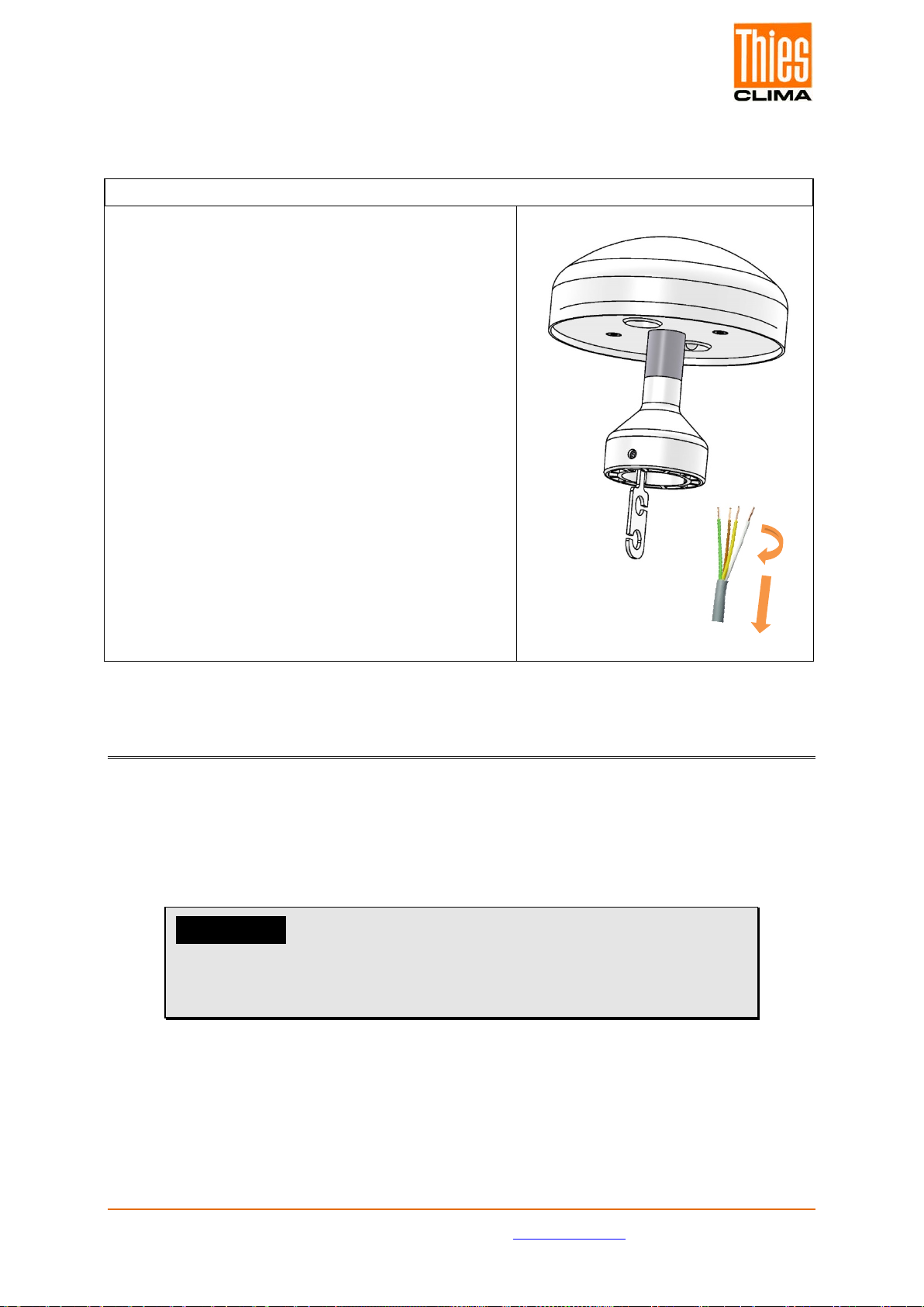
1. Preparing and connecting of supply-/ data cable
Tools:
Wire strippers
Small needle-nosed pliers, if necessary
Procedure:
1. Strip outer isolation of the cable by 5cm.
2. Strip the now exposed single cable by 1
cm.
3. Twist exposed cable strands each by
hand clockwise or counterclockwise
(depending on nature of cable).
4. Plug all prepared cable strands
successively, by hand, in the marked
clamp connection.
Sensor
A = DATA +
+ = 24V
B = DATA -
- = GND
Optionally, small needle-nosed pliers might be
required as support.
5. Check all cable strands for firm clamping
by slight pulling.
6. Fix strain-relief at the cable, and put it
into the provided strain-relief hole at the
sensor base.
Remark:
If necessary, pull the cable through mast, tube,
etc. before cable preparation.
Fig.: Cable
Fig. Sensor base with clamp connections
Fig.: Sensor with strain-relief

© Adolf Thies GmbH & Co. KG · Hauptstraße 76 · 37083 Göttingen · Germany 022028/02/23
Phone +49 551 79001-0 · Fax +49 551 79001-65 · inf[email protected] ·www.thiesclima.com Page 10 of 40
2. Putting the sensor onto mast, support, tube etc.
Tools:
Allen key size 2
Procedure:
1. If not yet done, lead the cable through the bore hole
of mast, tube, bracket etc.
2. Put weather station onto mast, tube.
3. Align weather station to „north” (procedure see
chapter 3. Positioning / northward orientation)
4. Secure weather station by M4-hexagon socket
screws.
Attention:
The hexagon socket screw is to
be tightened by max. 0.6Nm.
Remark:
Tube and mounting angle are not included in delivery.
3. Positioning / northward orientation
Tool:
Allen key Gr. 2
Procedure:
1. Detect a prominent object in the surrounding area
(tree, building etc.) in north direction by means of a
compass.
2. Via the north marking (N) and an imaginary north-
south axis the weather station is to be located on the
prominent object.
3. Align weather station.
The north marking must indicate to the geographic
north.
4. In case of match the weather station is to be secured
by an M4- hexagon socket screw.
Attention:
The hexagon socket screw is to
be tightened by max. 0.6Nm.
Remark:
With the north alignment by means of a compass, the local variation (deviation in direction of
a compass needle from the true north direction) by interfering magnetic fields, and magnetic
field influences by hardware and electric cable are to be considered.

© Adolf Thies GmbH & Co. KG · Hauptstraße 76 · 37083 Göttingen · Germany 022028/02/23
Phone +49 551 79001-0 · Fax +49 551 79001-65 · inf[email protected] ·www.thiesclima.com Page 11 of 40
4.3 Electrical connection
Sensor / terminal
connector
Function
A = DATA +
+ = Power 24 VDC
B = DATA -
-= GND (for Power 24 VDC)
4.3.1 Cable
The cable to be used for connection should have the following properties:
4 Cable wires, 0,28 … 0,5mm² wire cross-section, cable diameter max. 5.0mm, resistant to
ultraviolet rays, overall shielding.
Attention:
The voltage drop on the cable must be taken into consideration with long cable connections,
so that the supply voltage for the Weather Station Compact WSC10is guaranteed.
Calculation of the voltage drop on the cable. ULtg = RL* I; R = 2 ∗ ∗ A
⁄; ρ(rho) = 0,018
Example: I = 0,3A, A = 0,14mm², L = 100m
R = 2 ∗ ∗ A
⁄, R = 25,7Ω
ULtg = RL* I, ULtg = 7,7V
© Adolf Thies GmbH & Co. KG · Hauptstraße 76 · 37083 Göttingen · Germany 022028/02/23
Phone +49 551 79001-0 · Fax +49 551 79001-65 · inf[email protected] ·www.thiesclima.com Page 12 of 40
4.4 Disassembly of the supply / data cable
Disassembly of supply- / data cable
Tools:
Allen key size 2
Procedure:
1. Disconnect power supply and data
acquisition.
2. Remove weather station from mast, tube,
support etc. by loosening the M4-hexagon
socket screws.
3. Withdraw strain-relief from base of weather
station.
4. Grab single cable wire by finger and thumb.
5. Twist cable strand, thus removing it from the
cable clamp.
This procedure is to be carried out
successively with fixed cable strands.
5 Maintenance
As the device does not have any moving parts, i.e. is not subject to wear during operation,
only minimal servicing is required.
Depending on the location the instrument might pollute. The cleaning should be carried out
by means of water and a soft cloth. Aggressive cleaning agents must not be used.
Please note:
During storage, installation, de-installation, transport or
maintenance of the Weather Station Compact WSC10
make sure that no water gets into the device or connector.

© Adolf Thies GmbH & Co. KG · Hauptstraße 76 · 37083 Göttingen · Germany 022028/02/23
Phone +49 551 79001-0 · Fax +49 551 79001-65 · inf[email protected] ·www.thiesclima.com Page 13 of 40
6 Interface
The interface to the Weather Station consists of a RS485 link (half-duplex mode), with the
following data format:
•9600baud (the baud rate can be selected with command BR).
•8data bits.
•No parity.
•1stop bit.
•Data in ASCII format (command interpreter: THIES).
•Data in binary format (command interpreter: MODBUS RTU).
The behavior (configuration) of the Weather Station can be changed using the available
commands (see Commands and description).
For the command interpreter Thies-type the query of the measuring values is carried out by
command TR.
When the Weather Station starts up, the character string "Weather Station", software version,
hardware version and serial number is output:
Sample: Weather Station
V00.04
509914 v12-17
12030123
6.1 Command interpreter THIES
The Weather Station is equipped with a command interpreter of THIES-type, which can be
used to change the behaviour of the device. This allows you for example to adjust the
averaging periods for wind speed and wind direction. Commands basically have the following
structure:
•<id><command><CR> (No parameter: used to interrogate the selected
parameter).
•<id><command><parameter><CR> (With parameter: used to set a new parameter).
id: identification number ("00" to "99")
command: command encompassing 2 characters (see list of commands)
parameter: parameter value with between 1 to 10 positions
(decimal value in ASCII format)
<CR>: carriage return (13dec; 0x0D)
The 'id' identification number allows several devices to be operated together in a bus system.
Every device is assigned its own 'id' (see command ID).
A transmitted command is acknowledged with an echo telegram. The echo telegram starts
with a "!" followed by the id, command and value selected. It ends with the characters
"carriage return" and "new line".
Commands can be transmitted with or without a parameter. If no parameter is specified, the
set value will be output.

© Adolf Thies GmbH & Co. KG · Hauptstraße 76 · 37083 Göttingen · Germany 022028/02/23
Phone +49 551 79001-0 · Fax +49 551 79001-65 · inf[email protected] ·www.thiesclima.com Page 14 of 40
Example: 00BR<CR>
!00BR00005<CR>
If a command is transmitted with a parameter, the parameter is verified. If it is valid, it will be
saved and specified in the echo telegram. If the parameter is invalid, it will be disregarded
and the set value output in the echo telegram.
Examples:
00BR00005<CR> transmission command
!00BR00005<CR> echo telegram (parameter valid and password OK)
00BR00004<CR> transmission command
!00BR00005<CR> echo telegram (parameter valid but key incorrect)
Note:
The values measured by the sensor can be queried with the
command TR.
In this case the Weather Station does not respond with the echo
telegram, but with the requested data telegram!
To avoid any unintentional change in parameters, some commands (see list of commands)
are protected with a password. This password must be transmitted before the actual
command.
Example: Change baud rate
00KY234<CR> Release commands of user level
00BR4<CR> Set baud rate to 4800
!00BR00004<CR> Baud rate set to 4800
The Weather Station supports 3 different password levels.
•User level (password: "234").
•Calibration data level.
•Administrator level.
Please note:
Password-protected commands are released as long as
one of the following conditions is satisfied:
- the supply voltage is switched
- command 00KY0<CR> is transmitted
- no new command is transmitted for min. 120s.

© Adolf Thies GmbH & Co. KG · Hauptstraße 76 · 37083 Göttingen · Germany 022028/02/23
Phone +49 551 79001-0 · Fax +49 551 79001-65 · inf[email protected] ·www.thiesclima.com Page 15 of 40
6.1.1 Data telegrams
Data output takes place in response to a request with the command TR. You can choose
between the following telegrams:
•Measured value telegram (parameter=1, weather station WSC11 compatible)
•Sensor data telegram (parameter=2)
•Extended measured value telegram (parameter=3, including 4 brightnesses)
Calculation of the checksum, the composition of the status word and the control
characters/separators used in the telegrams are described below.
Control characters:
CR – Carriage return (13dec; 0x0D)
LF – Line feed (10dec; 0x0A)
STX – Start of text (2dec; 0x02)
ETX – End of text (3dec; 0x03)
Separators:
The semicolon ';' is used as the separator between the individual measured values in the
string.
The checksum separator is the multiplication sign '*'.
Checksum:
The checksum is the XOR link of all characters between <STX> and the byte <*>.
The asterisk acts as the separator from the checksum and is no longer included in the
checksum.
Status:
The Weather Station includes a status word (32-bit) which supplies information about the
status of the Weather Station. The measured values undergo a plausibility check and are
shown in the status word.
Bit number
Function
Description
Bit 0 Precipitation sensor =1, bedewing protection active.
Bit 1 Precipitation sensor =1, drying phase of sensor surface.
Bit 2 GPS data =1, no valid RMC telegram received.
Bit 3 RTC data from GPS
receiver =1, time from GPS receiver invalid.
Bit 4 ADC values =1, values from analog-digital-converter invalid.
Bit 5 Reserved =1, Reserved
Bit 6 Brightness north =1, measured value from brightness sensor north invalid.
Bit 7 Brightness east =1, measured value from brightness sensor east invalid.

© Adolf Thies GmbH & Co. KG · Hauptstraße 76 · 37083 Göttingen · Germany 022028/02/23
Phone +49 551 79001-0 · Fax +49 551 79001-65 · inf[email protected] ·www.thiesclima.com Page 16 of 40
Bit number
Function
Description
Bit 8 Brightness south =1, measured value from brightness sensor south invalid.
Bit 9 Brightness west =1, measured value from brightness sensor west invalid.
Bit 10 Twilight =1, measured value for twilight invalid.
Bit 11 Global irradiance =1, measured value from global irradiance sensor invalid.
Bit 12 Air temperature =1, measured value from air temperature sensor invalid.
Bit 13 Precipitation =1, measured value from precipitation sensor invalid.
Bit 14 Wind speed =1, measured value from wind speed sensor invalid.
Bit 15 Wind direction =1, measured value from wind direction sensor is invalid.
Bit 16 Humidity sensor =1, Readings from the humidity sensor invalid (relative
humidity, absolute humidity, dew point temperature).
Bit 17 Watchdog Reset =1, letzter Neustart durch Watchdog-Reset.
Bit 18 EEPROM Parameters =1, internal EEPROM parameters invalid.
Bit 19 EEPROM Parameters =1, internal EEPROM parameters contain the Standard-
values.
Bit 20 New FW =1, last restart was carried out with new firmware.
Table 1 : Status word
6.1.1.1 Measured value telegram
The Weather Station responds to the command "00TR1\r" with the measured value telegram.
Only 4 brightness sensors are considered in this telegram. The telegram is compatible with
the weather station WSC11. The telegram structure is shown in the following table:
Position
Length
Example
Description
1
1
<STX>
Start of text characters (0x02).
2
3
WSC
Designates the weather station compact WSC10.
5
1
;
Semicolon.
6
2
##
Identification number of weather station.
8
1
;
Semicolon.
9
19
dd.mm.yyyy
hh:mm:ss
Date and time separated with a blank character
dd: day, mm: month, yyyy: year, hh: hour, mm: minute, ss:
second.
28
1
;
Semicolon.
29
6
######
Specifies time format:
UTC
CEST
CET
UTC+xh
35
1
;
Semicolon.
36
5
###.#
Brightness north (kLux).
41
1
;
Semicolon.
42
5
###.#
Brightness east (kLux).
47
1
;
Semicolon.
48
5
###.#
Brightness south (kLux).
53
1
;
Semicolon.
54
5
###.#
Brightness west (kLux).
59
1
;
Semicolon.

© Adolf Thies GmbH & Co. KG · Hauptstraße 76 · 37083 Göttingen · Germany 022028/02/23
Phone +49 551 79001-0 · Fax +49 551 79001-65 · inf[email protected] ·www.thiesclima.com Page 17 of 40
Position
Length
Example
Description
60
3
###
Twilight (Lux).
63
1
;
Semicolon.
64
4
####
Global irradiance (W/m2).
68
1
;
Semicolon.
69
5
###.#
Air temperature (°C).
74
1
;
Semicolon.
75
1
#
Precipitation status (0: no precipitation, 1: precipitation).
76
1
;
Semicolon.
77
4
##.#
Average1wind speed (m/s).
81
1
;
Semicolon.
82
3
###
Average1wind direction (°).
85
1
;
Semicolon.
86
6
----.-
Reserved.
92
1
;
Semicolon.
93
6
----.-
Reserved.
99
1
;
Semicolon.
100
5
###.#
Inside temperature of housing (°C).
105
1
;
Semicolon.
106
5
###.#
Relative humidity (% r.h.).
111
1
;
Semicolon.
112
6
###.##
Absolute humidity (g/m³).
118
1
;
Semicolon.
119
5
###.#
Dew-point temperature (°C).
124
1
;
Semicolon.
Position
Length
Example
Description
125
11
####.######
Degree of longitude (°) (GPS position)
Positive sign for longitude in eastern direction.
Negative sign for longitude in western direction.
135
1
;
Semicolon.
136
1
##.######
Degree of latitude (°) (GPS position).
137
10
###.######
Latitude (°) (GPS position).
Positive sign for latitude in northern direction.
Negative sign for latitude in southern direction.
147
1
;
Semicolon.
148
5
###.#
Position of the sun, elevation or resp. elevation angle (°).
On sunrise and sunset elevation equals 0°.
Between these distinctive points (i.e. intraday) the elevation
takes positive values.
153
1
;
Semicolon.
154
5
###.#
Position of the sun, azimuth or resp. geographic direction (°).
The azimuth is counted positively from the north to the south.
0° = north ; 180° = south.
159
1
;
Semicolon.
160
8
########
32-bit sensor status in hexadecimal format (0000 – FFFFFFFF).
168
1
*
Asterisk as separator for checksum.
169
2
##
8-bit checksum in hexadecimal format (00 – FF). The checksum
is calculated from the exclusive OR link of all characters after
STX to the character before "*".
171
1
<ETX>
End of text characters (0x03).

© Adolf Thies GmbH & Co. KG · Hauptstraße 76 · 37083 Göttingen · Germany 022028/02/23
Phone +49 551 79001-0 · Fax +49 551 79001-65 · inf[email protected] ·www.thiesclima.com Page 18 of 40
Position
Length
Example
Description
172
1
<CR>
Carriage return (0x0D).
173
1
<LF>
Line feed (0x0A).
Table 2 : Measured value telegram
Measured values
The measured values are 1-second average values, with the exception of wind speed and
wind direction.
If the specified measuring range is exceeded (see Te), the measured value is limited to the
maximum (terminal value of measuring range) and the relevant bit set in the status (see
table 1: Status world).
6.1.1.2 Sensor data telegram
The Weather Station responds to the command "00TR2\r" with the sensor data telegram.
The telegram structure is given in the following table:
Position
Length
Example
Description
1
1
<STX> 0x02
Start of text characters.
2
10
##########
Serial number.
12
1
;
Semicolon.
13
5
##-##
HW version (e.g. 06-11).
18
1
;
Semicolon.
19
5
##.##
SW version (e.g. 01.00).
24
1
;
Semicolon.
25 6 ####.# Height of Weather Station referred to height above sea level in
metres, derived from the GPS data (Geoid Model).
31
1
*
Asterisk as separator for the checksum.
32 2 ## 8-bit checksum in hexadecimal format (00 – FF). The
checksum is calculated from the exclusive OR link of all
characters after STX to the character before "*".
34
1
<ETX> 0x03
End of text characters.
35
1
<CR> 0x0D
Carriage return.
36
1
<LF> 0x0A
Line feed.
Table 3 : Sensor data telegram
© Adolf Thies GmbH & Co. KG · Hauptstraße 76 · 37083 Göttingen · Germany 022028/02/23
Phone +49 551 79001-0 · Fax +49 551 79001-65 · inf[email protected] ·www.thiesclima.com Page 19 of 40
6.2 Command Interpreter MODBUS RTU
Once the command interpreter is selected the transmitted bytes are interpreted according to
the MODBUS specification (http://www.modbus.org/). Here, the Weather Station Compact
WSC10 is representing a MODBUS Slave.
The data transmission is carried out in packages, so-called frames, of maximum 256 bytes.
Each package contains a 16bit CRC checksum (initial value: 0xffff).
Slave-Address
Function code
Data
CRC
1byte
1byte
0...252byte(s)
2bytes
CRC low-byte
CRC high-byte
Table 4 : MODBUS Frame
The following MODBUS functions are supported:
- 0x04 (Read Input Register).
- 0x03 (Read Holding Registers).
- 0x06 (Write Single Register).
- 0x10 (Write Multiple Registers).
The Weather Station Compact WSC10 supports a write access for the slave-address 0
(“Broadcast”).
All received MODBUS request are checked for validity before carrying out. In error case the
weather station responds with one of the following exceptions (MODBUS Exception
Responses).
Code
Name
Signification
0x01
ILLEGAL FUNCTION
The function code in the request is not allowed for the
register address.
0x02
ILLEGAL DATA
ADDRESS
The register address in the request is not valid.
0x03
ILLEGAL DATA VALUE
The stated data in the request are not allowed.
Table 5: MODBUS Exceptions

© Adolf Thies GmbH & Co. KG · Hauptstraße 76 · 37083 Göttingen · Germany 022028/02/23
Phone +49 551 79001-0 · Fax +49 551 79001-65 · inf[email protected] ·www.thiesclima.com Page 20 of 40
6.2.1 Measuring Values (Input Register)
All measuring values of the Weather Station Compact WSC10 consume 32Bit, i.e. 2
MODBUS register addresses. The following table shows the allocation of measuring value to
register address, while the measuring values are sorted as follows:
- By measuring value type (30001 to 34999).
- In unbroken sequence (35001 to 39999).
Register
address
Parameter Name
Unit
Multiplicator
Explanation
Data
type
30001
Wind speed
m/s
10
value / 10
(1 decimal place, e.g.
101=10.1m/s)
U32
30003
Mean value
Wind speed
m/s
10
value / 10
(1 decimal place, e.g..
101=10.1m/s)
U32
30201
Wind direction
°
10
value/ 10
(1 decimal place, e.g.
1010=101.0°)
U32
30203
Mean value
Wind direction
°
10
value / 10
(1 decimal place, e.g.
1010=101.0°)
U32
30401
Air temperature
°C
10
value / 10
(1 decimal place, e.g.
255=25.5°C)
S32
30403
Interior temperature
of housing
°C
10
value / 10
(1 decimal place, e.g.
355=35.5°C)
S32
30601
relative humidity
%r.h.
10
value/ 10
(1 decimal place, e.g.
355=35.5°r.F.)
U32
30603
absolute humidity
g/m³
100
value / 100
(2 decimal places, e.g.
923=9.23g/m^3)
U32
30605
Dew point
temperature
°C
10
value / 10
(1 decimal place, e.g.
115=11.5°C)
S32
31001
Global radiation
W/m²
10
value / 10
(1 decimal place, e.g
10000=1000.0W/m^2)
S32
31201
Brightness north
kLux
10
value / 10
(1 decimal place, e.g.
1200=120.0kLux)
U32
31203
Brightness east
kLux
10
value / 10
(1 decimal place, e.g.
U32
Table of contents
Other Thies CLIMA Weather Station manuals


