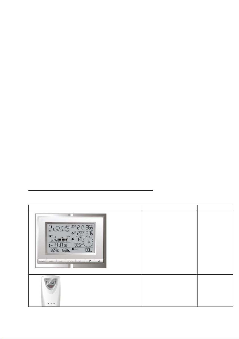
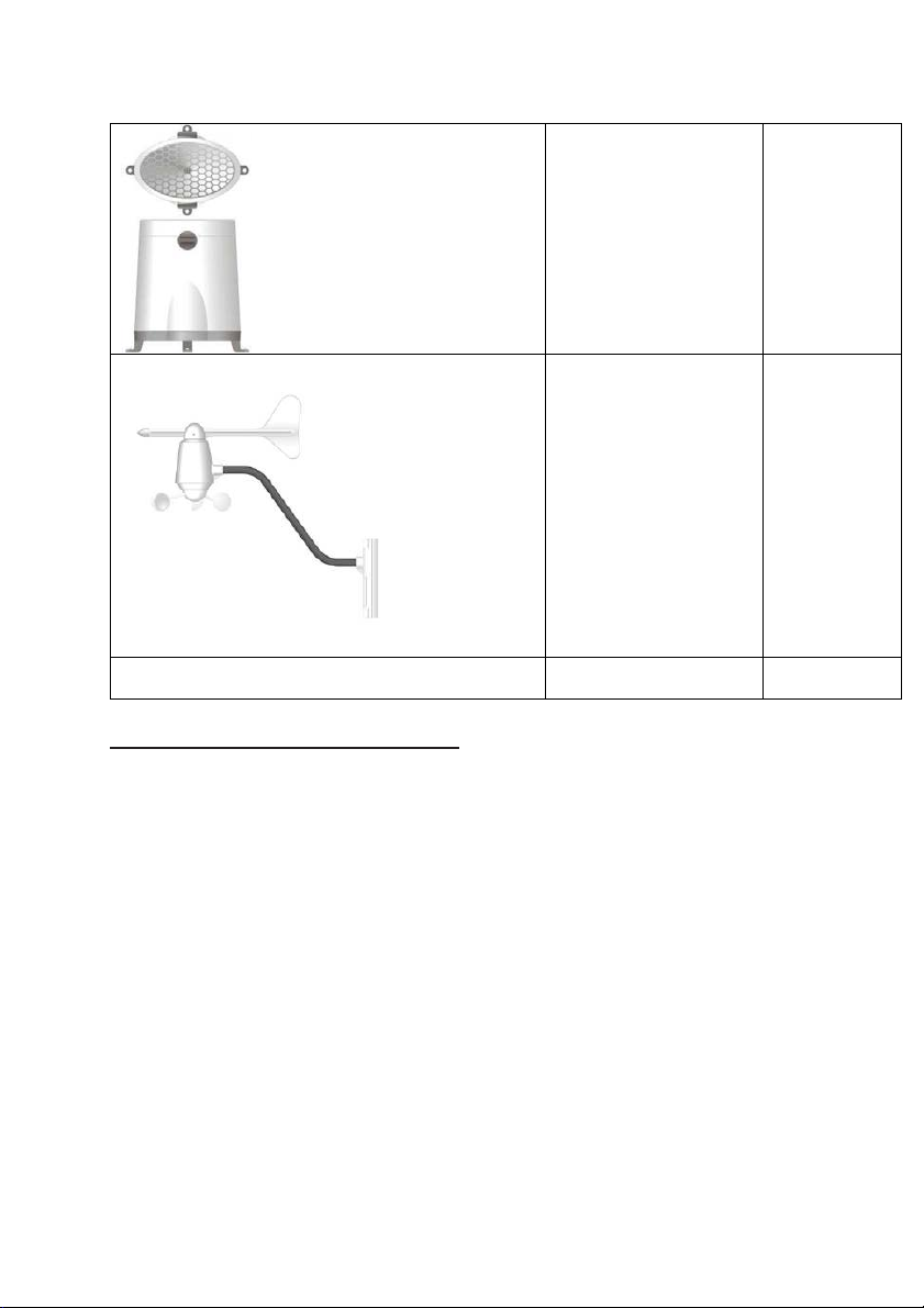
Ventus W831 User manual

Authorised UK & Ireland Distributor
Outline House, 73 Guildford Street, Chertsey, Surrey KT16 9AS
Tel:
0845 2300 599
(Local Call Number) Tel: 01932 567 333 (Direct Dial Number)
USER MANUAL
USER MANUAL
VENTUS W831
VENTUS W831
WEATHER STATION
WEATHER STATION
Introducing the next level of professional weather stations

0
VENTUS W831
ENGLISH………………………...……………………..PAGE 01
DANISH..………………………………………………..PAGE 35
GERMAN…………….…………………………………PAGE 68

1
This Operation Manual is part of this product and should be kept in a safe place
for future reference. It contains important notes on setup and operation.
Introduction
Congratulations on your purchase of the VENTUS W831 Weather Station. The
weather station consists of a main console unit with remote sensors which collect
and transmit a wide range of weather data, including outdoor temperature,
humidity, wind speed and direction, rain amount and rain rate.
Main Console Unit
The main console unit features a radio-controlled atomic precision clock with
alarm and weather forecast. It measures indoor temperature and humidity, and
displays weather data collected by the remote weather sensors. It also provides
indication of the indoor/outdoor temperature, pressure and humidity trends, and
celestial information such as moon phase, and sunrise/set times.
The main console unit stores around 200 weather records without a computer
connection.
Remote Weather Sensors
The remote weather sensors include a thermo-hygrometer, anemometer (wind
sensor) and rain sensor. All data collected by the sensors is transmitted to the
main console unit by wireless RF. The weather station supports a maximum of 5
thermo-hygrometers, allowing 5 channels of temperature/humidity display.
Features
Weather Forecast
- Sunny, Partly Cloudy, Cloudy, Slight Rain, Heavy Rain, Snow and Unstable
Weather conditions
Pressure
- Current or historical pressure (mBar/ hPa, mmHg or inHg)
- Altitude or sea level pressure adjustment for atmospheric pressure
compensation
- Pressure trend indication
- Sea-level pressure history for the last 24 days
- Sea-level pressure history bar chart
Moon phase
- 12 steps of moon symbols
- Scans moon phase for year 2000 to 2099

2
- Moon phase history for the last or future 39 days
Radio Controlled Clock
- Time and date synchronized by radio signal DCF77 (time and date also
manually adjustable)
Clock and Calendar (12hr/ 24 hr) (month/day or day/month)
- Different combinations of clock and calendar displays
- 6 languages for day of week (English/ German/ French/ Italian/ Spanish/
Dutch)
Alarms
- Single alarm: activated once at specified time
- Weekday alarm: activated everyday from Monday to Friday at specified
time
- Pre-alarm: activated ahead of single or weekday alarm if channel 1
temperature falling to +2ºC or below. (Programmable 15, 30, 45, 60 or 90
minutes)
- Programmable snooze function (1-15 minutes)
Sunrise time and sunset time
- Calculates sunrise/set times with geographical information provided by
user (DST, zone time offset, latitude, longitude)
- over 133 preset cities can be selected for automatic geographical
information input.
Remote temperature and relative humidity, with trend indication
- Indoor and outdoor temperature and relative humidity display (ºC or ºF)
- Temperature and relative humidity trend indication
- Dew point display
- Max and Min memory for temperature and relative humidity
Comfort level indicator
- Analyzes current environmental conditions (Comfort, Wet and Dry)
Rainfall measurement
- Records rainfall amount for the last hour, last 24 hours, last day, last week and
last month (inch or mm).
- Daily rainfall alert if rainfall for the current day exceed pre-specified amount.

3
Wind
- Temperature at place of anemometer.
- Temperature adjusted to wind chill factor. (ºC or ºF)
- Wind direction compass display. Wind direction angles available as
compass points or bearings.
- Average wind speed and gust speed (mph, m/s, knots, and km/h)
- Daily Maximum wind speed and gust speed memory.
- Wind speed alert for average wind speed and wind gust speed.
Memory Functions
-Stores 200 weather records (without a computer connection) with memory
saving intervals (1 hr default).
LED backlight
- Light sensor to automatically toggle backlight when environment lighting
level is low.
Can be turned on/off or set to automatic. (Should be used with AC/DC
adaptor for automatic control function)
Other Features
- Removable table stand for mounting display on a table or wall
Contents of Complete Weather Station Kit
Before installing your weather station, please check that the following are
complete:
Hardware Components Fittings
Main Console Unit
AC/DC 7.5V
output
adaptor
Thermo-Hygro Sensor

4
Rain Sensor:
-Funnel shaped Lid with
Battery Hatch
-Sensor Base
-Bucket See-saw
Mechanism
-Protective Screen
4 screws for
securing unit
to ground
Anemometer
(Wind Sensor):
- Wind Cups
- Wind Vane
- Anemometer arm
- Anemometer base
4 screws for
securing unit
to vertical
surface
Computer Software 2m (6ft) USB
cable
Installing your weather station
Setting up the Remote Weather Sensors
Before starting up the main console unit, setup all the remote sensors first.
When placing the sensors, make sure that they are within receiving range of the
console unit. Ideally they should be within the line of sight of the console unit.
Transmission range may be affected by trees, metal structures and electronic
appliances. Test reception before permanently mounting your weather station.
Also make sure that the sensors are easily accessible for cleaning and
maintenance.
The remote sensors should be cleaned on a weekly basis, since dirt and debris
will affect sensor accuracy.
Setting up the Thermo-Hygro Sensor(s)
1. Open the latch at the base of the thermo-hygro sensor.
2. Set the channel with a slide switch.

5
3. Insert two 2 x UM-3 or “AA” size 1.5V batteries.
4. Use a pin to press the “RESET” key which is in the battery compartment of
thermo-hygro sensors.
5. Replace the latch and mount unit at desired location.
Placement tips:
-The thermo-hygro sensor should be in an area with free air circulation
and sheltered from direct sunlight and other extreme weather conditions. Place
the unit in ashaded area, such as under a roof.
- Use the wall mount and fittings provided if mounting the unit on a vertical
surface.
- Avoid placing the sensor near sources of heat such as chimneys.
- Avoid any areas which collect and radiate heat in the sun, such as metal,
brick or concrete structures, paving, patios and decks.
- Ideally, place the sensor above natural surfaces such as a grassy lawn.
- The international standard height for measurements of air temperature is
at 1.25m (4 ft) above ground level.
Setting up the Rain Sensor
1. Unlock the funnel-shaped top of the rain sensor by turning both knobs on the
sides of the rain sensor in an anti-clockwise direction.
2. Lift the top off the base and insert two 2 x UM-3 or “AA” size 1.5V batteries into
the battery holder.
3. Replace the lid and secure into place by turning the knobs clockwise.
4. Place the rain sensor in a location such that precipitation can fall directly into
the sensor, ideally 2-3 ft above the ground. It may be secured into place by using
the four screws provided.
5. The sensor must be accurately level for optimum performance. To check if the
sensor is level, remove the lid and check if the ball bearing inside is at the
midpoint of the leveler. Additionally, a bubble level or carpenter’s level may be
used.
6. Attach the protective screen onto the top of the lid. The screen will prevent any
debris entering the sensor.
Placement tips:
- The rain sensor should be placed in an open area away from walls,
fences, trees and other coverings which may either reduce the amount of rainfall
into the sensor, deflect the entry of wind-blown rain, or create extra precipitation
runoff. Trees and rooftops may also be sources of pollen and debris.
- To avoid rain shadow effects, place the sensor at a horizontal distance

6
corresponding to two to four times the height of any nearby obstruction.
- It is important that rain excess can flow freely away from the sensor.
Make sure that water does not collect at the base of the unit.
- The rainfall measurement mechanism utilizes a magnet, hence do not
place any magnetic objects around the proximity of the sensor.
Setting up the Anemometer (wind sensor)
1. Assemble the wind cups and wind vane to the anemometer arm
2. Attach the assembled anemometer to the base.
3. Insert two 2 x UM-3 or “AA” size 1.5V batteries into the battery holder in the
base.
4. Mount the anemometer onto a vertical surface, using the fittings provided.
5. To allow the main console unit to find the direction which the wind vane is
oriented, the following procedures are required:
i. Insert the batteries
ii. Point the wind vane towards the north. Use a compass or map if
necessary.
iii. Use a pin to press the “SET” key which is in the battery compartment of the
wind sensor.
Note: Above procedure must be repeated for changing battery.
The “SET” will toggle the direction between two mode:
1. Let the wind direction as manufacturer design. It will be as a default setting
after
2. Set the current direction as NORTH.
Placement tips:
- Check that wind can travel freely around the anemometer and is not
distorted by nearby buildings, trees or other structures.
- For better results, place the anemometer at least 3m above local
structures and obstacles. The ground creates a frictional effect to wind flow and
will attenuate readings.
- Aim for maximum exposure of the anemometer to the commonest wind
directions in your area.
- The official mounting location for anemometers is 10m (33 ft) above
ground level in a clear unobstructed location.
Setting up the Main Console Unit
1. Open the latch at the back of the main console unit.
2. Insert 4 x UM-3 or “AA” size 1.5V batteries according to the polarities shown.

7
3. Reattach the latch.
4. You are highly recommended to connect the AC/DC adaptor. For the feature of
the automatic backlight control function, the AC/DC adaptor must be used.
5. If placing the console unit on a table or horizontal surface, set up the table
stand and you can put it on table.
6. If mounting the console unit on a wall or vertical surface, remove the table
stand and use the fitting provided.
Placement tips:
Make sure that the console unit is within receiving range of all remote sensors.
Ideally sensors should be within the line of sight of the console unit. Transmission
range may be affected by trees, metal structures and electronic appliances. Test
reception before permanently mounting your weather station.
The console unit measures indoor temperature, humidity, pressure and receives
signals from all remote sensors and radio-clock broadcasts. Avoid placing the
console unit in the following areas:
- Direct sunlight and surfaces which radiate and emit heat.
- Near heating and ventilation devices, such as heating ducts or air conditioners.
- Areas with interference from wireless devices (such as cordless phones, radio
headsets, baby listening devices) and electronic appliances.
Starting up the Main Console Unit
Once the console unit is properly powered, the display will start showing some
data and weather parameters. Wait for a few minutes for the console to finish
self-calibration and for the sensor readings to show up.
If “---” is still displayed for the sensor reading(s), check the wireless transmission
path and the batteries for the corresponding sensor.

8
Using your Weather Station
Buttons and Controls
The following controls are available on the main console unit.
UP ( )
- Switches to next mode in clockwise direction
- Increment for setting parameters
DOWN ( )
- Switches to next mode in anti-clockwise direction
- Decrement for setting parameters
SET
- Rotates display for current mode
- Press and hold to enter setup or change units
- Confirmation for setting parameters
MEMORY
- Shows records for moon phase, temperature, humidity, rain and wind.
HISTORY
- Shows history for sea-level pressure
ALARM
CHART
- Shows time alarms and alerts for temperature, rain and wind.
- Press and hold to enter alarm/alert setup
- Press and hold in Pressure and Weather Forecast Mode to view

9
different bar-charts
CHANNEL
- Changes temperature and humidity display to
selected channel
- Press and hold to enable cycling display of channel
temperature and humidity
LIGHT/SNOOZE
- Turns on backlight for 5s
- Enters Snooze mode when alarm is activated
LIGHT SENSOR
– AUTO, ON, OFF
-Toggles the light sensor function to automatic, on or off
SENSITIVITY
– HIGH/LOW
-Adjusts the sensitivity of the light sensor
Navigating between Different Modes
There are 6 modes available on the main console unit, and each one displays a
different category of data. When display is in a certain mode, its corresponding
icon will start flashing.
To navigate between the different modes from the main console unit, press
( ) to cycle through the modes in a clockwise direction or ( to cycle
through the modes in an anti-clockwise direction.
Pressure and Weather Forecast Mode
- Current pressure, trend, and history bar-chart
- Weather forecast
- Moon phase

10
Clock and Alarm Mode
- Radio Controlled clock showing current time and calendar
- Single alarm, weekday alarm and pre-alarm
Sunrise/Sunset Mode
- Sunrise and sunset times
- Longitude and Latitude of local area

11
Temperature and Humidity Mode
- Temperature and humidity trend and readings for indoor and selected channel
- Comfort level
- Dew point
- Temperature alerts
Wind Mode
- Wind Chill
- Temperature at place of anemometer
- Wind direction
- Wind speed
- Wind gust
- Alert for wind speed and wind gust speed

12
Rain Mode
- Precipitation amount for last hour, last 24 hour, yesterday, last week and last
month
- Rainfall alert
Customizing your Weather Station
To fully customize the weather station to your local settings and personal
preferences, the following settings are required. Please refer to the appropriate
sections for detailed instructions.
Required:
- Setting Pressure Parameters during Initial Start-Up (Pressure and
Weather Forecast Mode)
- Setting up the Time, Date and Language (Clock and Alarm Mode)
- Setting up the Location Data (Sunrise/Sunset Mode)
Optional:

13
- Setting up the Time Alarms (Clock and Alarm Mode)
- Setting up the Temperature Alerts (Temperature and Humidity Mode)
- Setting up the Daily Rainfall Alerts (Rain Mode)
- Setting up the Wind Alerts (Winds Mode)
LED Backlight Options
The backlight of the main console unit can be turned permanently on/off or
automatically toggled when environment lighting level is low. Use the light sensor
switch at the back of the unit to select lighting preferences.
For the automatic backlight function, the sensitivity of the light sensor can be
adjusted to high or low with the sensitivity switch also on the back of the console
unit.
Note: Console unit must be powered with AC/DC adaptor for automatic control
function
Using the Different Weather Modes
Pressure and Weather Forecast Mode
This part of the display indicates the current pressure, sea level pressure,
weather forecast, moon phase and pressure trend.
A number of historical statistics can also be viewed, such as the sea-level
pressure values for the last 24 hours, moon phase for the previous and next 39
days, as well as a pressure/ temperature/ humidity history bar-chart.
Pressure values may be displayed inHg, hPa/mBar or mmHg, and altitude values
may be displayed in meters or feet.
Accessing Pressure and Weather Forecast Mode
Press ( ) or ( ) until the weather forecast icon on the upper left of
the display starts flashing.
Setting Pressure Parameters during Initial Start-Up
During the initial start-up of the main console unit, all functions in Pressure and
Weather Forecast mode will be locked until the pressure settings are configured.
1. Choose Pressure Units:
The unit icon “inHg” or “mmHg” or “hPa/mBar” should be flashing. Press
() or ( ) to select pressure unit as inHg, hPa/mBar or mmHg
Press SET to confirm your selection.

14
2. Choose Altitude Units:
Press ( ) or ( ) to select altitude unit as feet or meters.
Press SET to confirm your selection.
3. Set Altitude:
Press ( ) or ( ) to adjust value. Press and hold either button for
fast advance.
Press SET to confirm your selection.
4. Upon completion the display will be returned to Pressure and Weather
Forecast Mode.
Note: After initial start-up the altitude cannot be adjusted again until the main
console unit is restarted.
Viewing Pressure and Altitude Data
In Pressure and Weather Forecast Mode, each press of SET rotates display
between:
- Sea level pressure
- Local pressure
- Local altitude
Setting the Sea Level Pressure
1. In Pressure and Weather Forecast Mode, press SET until the sea level
pressure is displayed.
2. Press and hold SET. The Sea Level Pressure display should be flashing.
3. Set Sea Level Pressure:
Press ( ) or ( ) to adjust value. Press and hold either button for
fast advance.
Press SET to confirm your selection.
4. Upon completion the display will be returned to Pressure and Weather
Forecast Mode.
Setting the Pressure and Altitude Units
1. In Pressure and Weather Forecast Mode, press SET until local pressure is
displayed.
2. Press and hold MEMORY. The pressure unit should be flashing.
3. Set Local Pressure Units:
Press ()or ( ) to adjust value.
Press SET to confirm your selection.
4. Set Altitude Units:

15
Press ( ) or ( ) to adjust value.
Press SET to confirm your selection.
5. Set Sea-Level Pressure Units:
Press ( ) or ( ) to adjust value.
Press MEMORY to confirm your selection.
6. Upon completion the display will be returned to Pressure and Weather
Forecast Mode.
Viewing the Sea Level Pressure History
1. In all modes, pressing HISTORY will toggle the sea level pressure display.
2. When sea level pressure is displayed, press HISTORY repeatedly to view sea
level pressure data for each of the last 24 hours.
3. If no buttons are pressed for 5s, the display automatically returns to Pressure
and Weather Forecast Mode.
Viewing the Pressure/ Temperature/ Humidity Bar-Charts
The bar-chart on the display can be configured to display the history data for
sea-level pressure, temperature or humidity for channel 1.
In Pressure and Weather Forecast Mode, press and hold [ ALARM ] to toggle the
bar-chart between:
- Sea-level pressure (“PRESSURE” should be displayed)
- Temperature (Thermometer icon and “CH1” should be displayed)
- Humidity (RH icon and “CH1” should be displayed)
Viewing Moon Phase History and Forecast
1. In Pressure and Weather Forecast Mode, press MEMORY.
2. “+ 0 days” should be flashing.
3. View Moon Phase History / Forecast:
Press ( ) or ( ) to choose number of days forward (+ days) or
backward (- days) from current date. Press and hold either button for fast
advance.
The corresponding moon phase will be shown.
4. To exit, press MEMORY.
Otherwise, if no buttons are pressed for 5s the display automatically
returns to Pressure and Weather Forecast Mode.

16
Understanding the Weather Forecast Display
Display Weather Forecast Status
Display Weather
Forecast
Status
Sunny
Partly Cloudy
Cloudy
Rain
Unstable
Weather
Snow
NOTE:
1. It is not necessary and not possible to adjust the altitude of the weather station.
After the initial start-up of the weather station, a first forecast will be made within
the first 24 hours of operation.
2. In periods of long stable weather conditions, it becomes difficult to make a
reliable forecast.
3. The weather forecast is solely calculated on the basis of barometric air
pressure changes.
4. The probability of a correct weather forecast is approximately 70% and is valid
for an area of approx. 20-30 km around the location of the weather station.

17
5. The forecast “Sunny” means at night “cloudless weather”. Fog is not indicated
by the weather station as this can occur with different weather conditions.
6. If you travel with the weather station, a reliable weather forecast will become
impossible due to changes in altitude and location. You’ll have to wait up to 24
hours so that the weather station can calculate a new forecast based on the
conditions at the new location.
Understanding the Moon Phase Diagram
Clock and Alarm Mode
The main console unit can be configured to display the time, calendar or UTC
time. There are three time alarms available on the console unit:
Single alarm: activated once at specified time
Weekday alarm: activated everyday from Monday to Friday at specified time
Pre-alarm: activated at specified time interval (Fixed 30 min) ahead of weekday
alarm, if channel 1 temperature falling to +2 ºC or below.
The snooze duration for the above alarms can also be programmed (0-15 min).
Accessing Clock and Alarm Mode
From the main console unit: Press ( ) or ( ) until the clock icon
beside the time/date display starts flashing.
Setting up the Time, Date and Language
1. In Clock and Alarm Mode, press and hold SET to enter clock and calendar
setup.
2. The day of week should start flashing in the display.
Set Language:
Press ( ) or ( ) to select language for day of week: English,
German, French,
Italian, Spanish or Dutch
Press SET to confirm your selection.
3. Select City Code:

18
Press ( ) or ( ) to select city code for your local area. Refer to
P.31 for a list of available codes.
Press SET to confirm your selection.
4. (if USR was chosen for city code) Set Minute for Latitude:
You will be asked to enter your latitude in minutes (º).
Press ( ) or ( ) to adjust value. Press and hold either button for
fast advance.
Press SET to confirm your selection. Repeat above procedure to set
seconds for latitude, minutes for longitude and seconds for longitude.
5. (if USR was chosen for city code) Set Time Zone:
Press ( ) or ( ) to adjust value in resolution of 30 min. Press and
hold either
button for fast advance.
Press SET to confirm your selection.
6. (if USR was chosen for city code or city is in a DST zone)
Set Daylight Saving Time Option:
Press ( ) or ( ) to turn DST option on or off. Press and hold either
button for fast advance.
Press SET to confirm your selection.
7. Repeat the above instructions to set year, month, day, calendar display format
(day/month or month/day), time display format (12 hr/ 24 hr), local hour and local
minutes.
8. Upon completion the display will return to normal Clock and Alarm Mode.
Note: Press and hold SET anytime during the setup to return to normal Clock and
Alarm Mode. All settings made will be discarded.
Rotating between Different Clock/Calendar Displays
In Clock and Alarm Mode, each press of SET rotates clock display between:
-Hour: Minute: Weekday
-Hour: Minute for UTC (Coordinated Universal Time)
-Hour: Minute: City
-Hour: Minute: Second
-Month: Day: Year (or Day: Month Year depending on settings)
Activating/Deactivating the Time Alarms
1. In Clock and Alarm Mode, each press of ALARM rotates clock display
between:
Table of contents
Languages:
Other Ventus Weather Station manuals

Ventus
Ventus W820 User manual

Ventus
Ventus W193-5 User manual

Ventus
Ventus W928-ULTIMATE User manual

Ventus
Ventus W154 User manual

Ventus
Ventus W161 User manual

Ventus
Ventus w160 User manual

Ventus
Ventus w160 User manual

Ventus
Ventus AOK-5005E User manual

Ventus
Ventus lonobox User manual

Ventus
Ventus W838 User manual